DVD
SERVICE
DOCUMENT CREATED IN JAPAN, Nov.,2004
FILE
810-200438
SD-P5000-S-TN
MANUAL
NO.
VIDEO PLAYER
y
Rev. 01
When the power supply is being turned on, you may not remove this laser cautions label. If you remove it, you may receive
radiation of laser.
LASER BEAM CAUTION LABEL
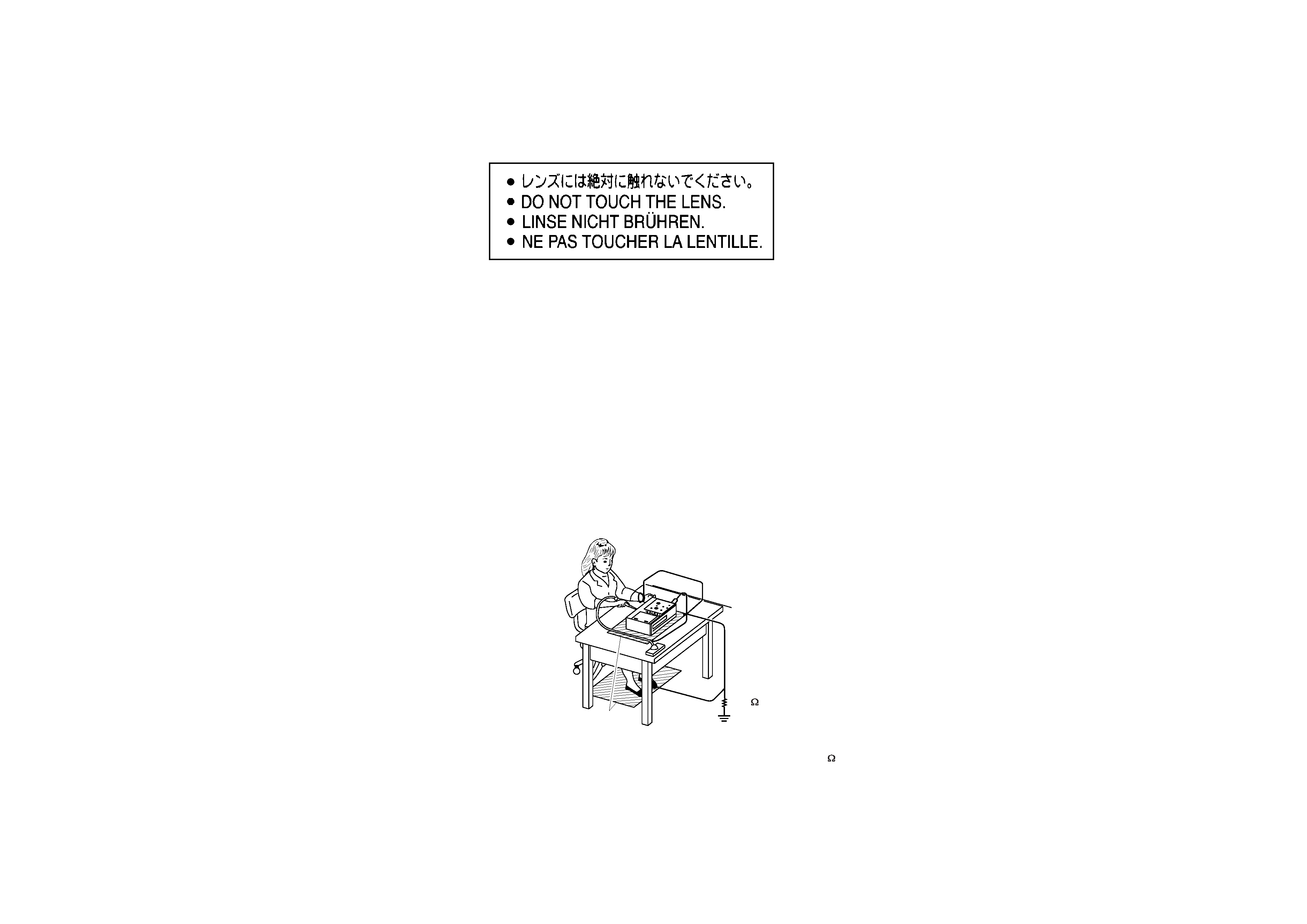
PREPARATION OF SERVICING
Pickup Head consists of a laser diode that is very susceptible to external static electrocity.
Although it operates properly after replacement, if it was subject to electrostatic discharge during replacement,
its life might be shortened. When replacing, use a conductive mat, soldering iron with ground wire,etc. to
protect the laser diode from damage by static electricity.
And also, the LSI and IC are same as above.
Soldering iron
with ground wire
or ceramic type
Ground conductive
wrist strap for body.
Conductive mat
The ground resistance
between the ground line
and the ground is less than 10
1M
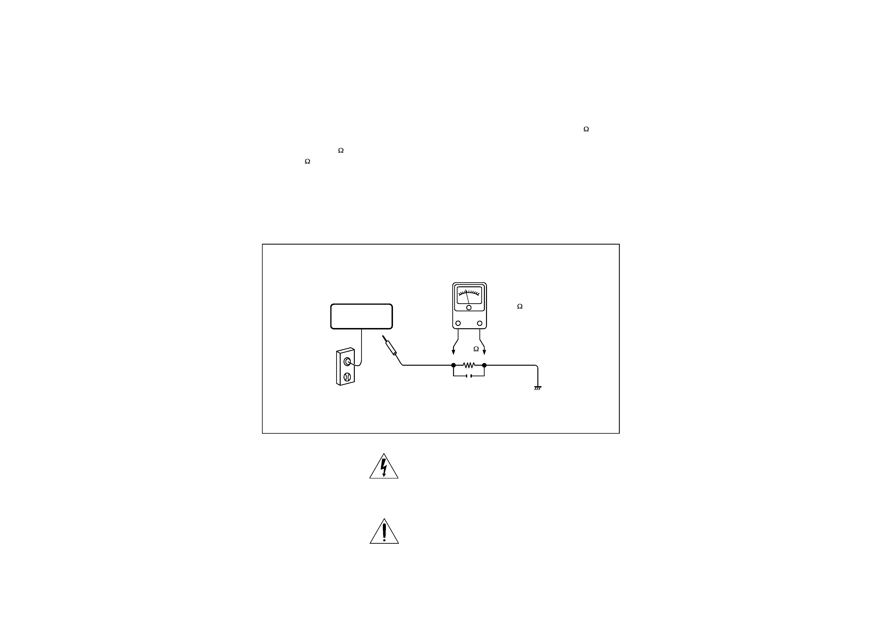
SAFTY NOTICE
Plug the AC line cord directly into a 120V AC outlet (do
not use an isolation transformer for this check). Use an
AC voltmeter, having 5000
per volt or more sensitivity.
Connect a 1500
10W resistor,paralleled by a 0.15uF
150V AC capacitor between a known good earth ground
(water pipe, conduit, etc.) and all exposed metal parts of
cabinet (antennas, handle bracket, metal cabinet
screwheads, metal overlays, control shafts, etc.).
SAFTY PRECAUTIONS
LEAKAGE CURRENT CHECK
Measure the AC voltage across the 1500
resistor.
The test must be conducted with the AC switch on and
then repeated with the AC switch off. The AC voltage
indicated by the meter may not exceed 0.3V.A reading
exceeding 0.3V indicates that a dangerous potential
exists, the fault must be located and corrected.
Repeat the above test with the DVD VIDEO PLAYER
power plug reversed.
NEVER RETURN A DVD VIDEO PLAYER TO THE
CUSTOMER WITHOUT TAKING NECESSARY
CORRECTIVE ACTION.
READING SHOULD NOT EXCEED 0.3V
DVD VIDEO PLAYER
AC OUTLET
AC VOLTMETER
Test all exposed metal.
Voltmeter Hook-up for Leakage Current Check
0.15uF 150V AC
1500
10W
(5000
per volt
or more sensitivity)
Good earth ground
such as a water pipe,
conduit, etc.
The lightning flash with arrowhead symbol, within an
equilateral triangle, is intended to alert the user to the
presence of uninsulated "dangerous voltage" within the
product's enclosure that may be of sufficient magnitude to
constitute a risk of electric shock to persons.
The exclamation point within an equilateral triangle is
intended to alert the user to the presence of important
operating and maintenance (servicing) instructions in the
literature accompanying the appliance.
XS307
XS05
XS4
XS311
XS3
XS1
XS2
XS005
XS300
U301
XS12
XS9
XS8
XS5
XS009
XS10
JX1
XS003
XS001
XS6
U1
CN7
CN6
CN1
CN9
CN8
CN2
CN3
XS2
XS305
R137
XS307
XS306
XS008
XS1
XS7
1
2
3
4
5
6
7
8
9
10
11
12
13
14
15
16
17
18
19
20
21
22
23
24
NC
LD/VCC
V20
GND
F
E
CD/DVD
SW
RF
C
D
B
A
VRCD
VRDVD
DVDMD
CDLD
GND
DVDLD
NC
VCC
FCS-
TRK+
TRK-
FCS+
1
2
3
4
5
6
7
8
9
10
11
12
13
14
15
16
17
18
19
20
21
22
23
24
1
2
3
4
5
6
1
2
3
4
5
6
SP+
SP++
SL+
SL-
GND
LIMIT
MECHANISM
1
2
3
4
5
6
7
8
9
10
CR
GND
CB
GND
CG
GND
GND
LL
GND
A
1
2
3
4
5
6
7
8
9
10
1
2
1
2
HV
DC0
OUTPUT1
1
2
3
4
5
6
7
8
KEYOUT3
KEYOUT2
KEYOUT1
KEYOUT0
KEYIN3
KEYIN2
KEYIN1
KEYIN0
1
2
3
4
5
6
7
8
KEY CONTROL1
1
2
1
2
LOUT
-
LOUT
£«
1
2
1
2
ROUT
-
ROUT
£«
1
2
3
4
5
6
7
8
9
10
11
12
13
14
15
16
17
18
19
20
DC
DC
DC
DC
GND
GND
GND
GND
GND
POCON
GND
KEYOUT2
KEYIN3
KEYIN2
KEYIN1
GND
L
GND
R
GND
1
2
3
4
5
6
7
8
9
10
11
12
13
14
15
16
17
18
19
20
1
2
3
4
1
2
3
4
KEYOUT2
KEYIN3
KEYIN2
KEYIN1
OUTPUT2
1
2
3
4
BATOUT
BATGND
1
2
3
4
BATTERY
1
2
3
4
5
6
7
BA+
BA+
400
BTC
GND
GND
GND
1
2
3
4
5
6
7
1
2
3
4
1
2
3
4
DCIN
DCIN
GND
GND
1
2
3
4
5
6
1
2
3
4
5
6
RMC5V
RMC
GND
P
BATLED
CPU5V
1
2
3
4
5
6
7
8
9
10
11
12
13
14
15
16
17
18
19
20
21
22
23
24
25
26
27
28
29
30
31
32
33
34
35
36
37
38
39
40
41
42
B05
GND
HD
VD
DENA
CLK
GND
RE1
RE2
RE4
GND
GE0
GND
GE3
GE5
GND
BE1
BE2
BE4
GND
B04
GND
GND
GND
GND
GND
GND
RE0
GND
RE3
RE5
GND
GE1
GE2
GE4
GND
BE0
GND
BE3
BE5
GND
GND
1
2
3
4
5
6
7
8
9
10
11
12
13
14
15
16
17
18
19
20
21
22
23
24
25
26
27
28
29
30
31
32
33
34
35
36
37
38
39
40
41
42
1
2
3
4
5
6
7
8
9
10
11
12
13
14
15
16
17
18
19
20
21
22
23
24
25
26
27
28
29
30
31
32
33
34
35
36
37
38
39
40
41
42
HV9V
TFT
ON/OFF
GND
GND
RMC
BA
TLED
P
ANEL3.3V
GND
R00
GND
R03
R05
GND
G01
G02
G04
GND
B00
GND
B03
HV9V
HV9V
PWM
GND
CPU5V
POWER
ON
P
ANEL3.3V
GND
GND
R01
R02
R04
GND
G00
GND
G03
G05
GND
B01
B02
GND
GND
1
2
3
4
5
6
7
8
9
10
11
12
13
14
15
16
17
18
19
20
21
22
23
24
25
26
27
28
29
30
31
32
33
34
35
36
37
38
39
40
41
42
SPEAK
SPEAK
KEY
CONTROL2
BATTERY
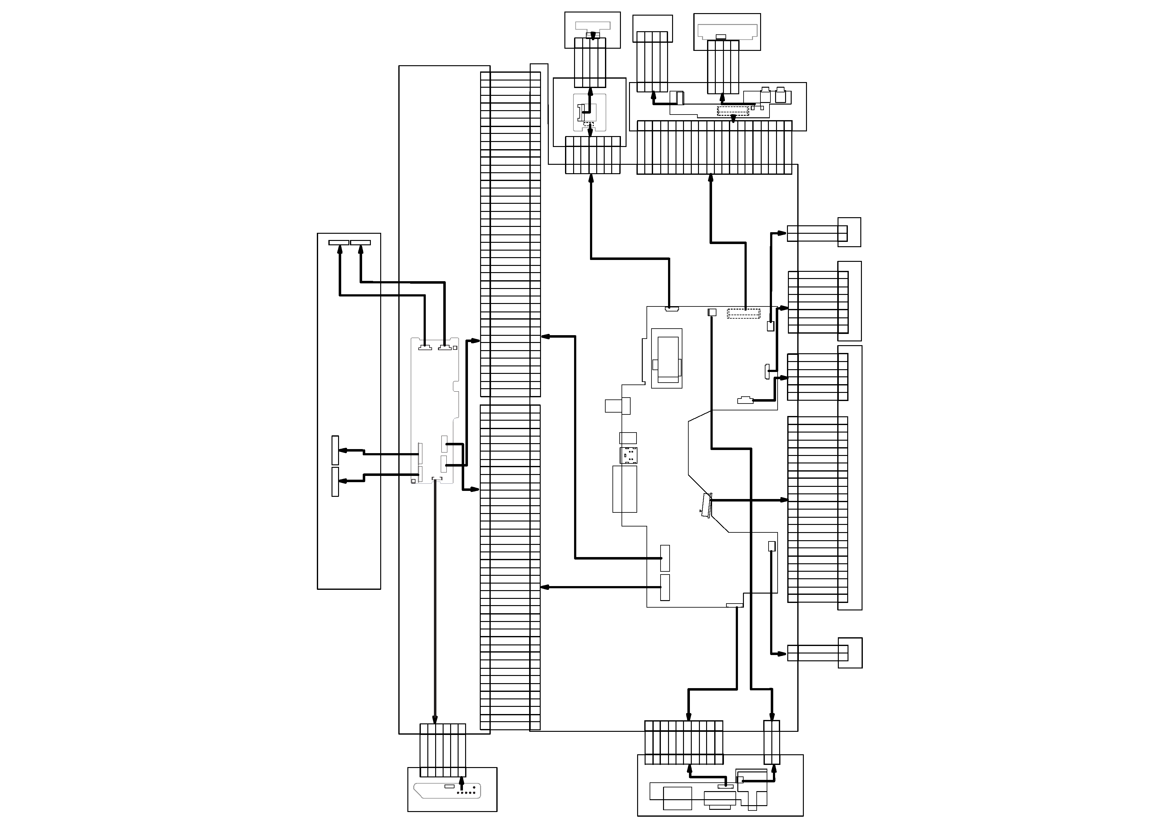
MH57
HV PCB
RMC
TFT LCD
MAIN PCB
RF AMP & SERVO & DVD PROCESSOR
MPEG-2 DECODER & VIDEO ENCODER
D3800
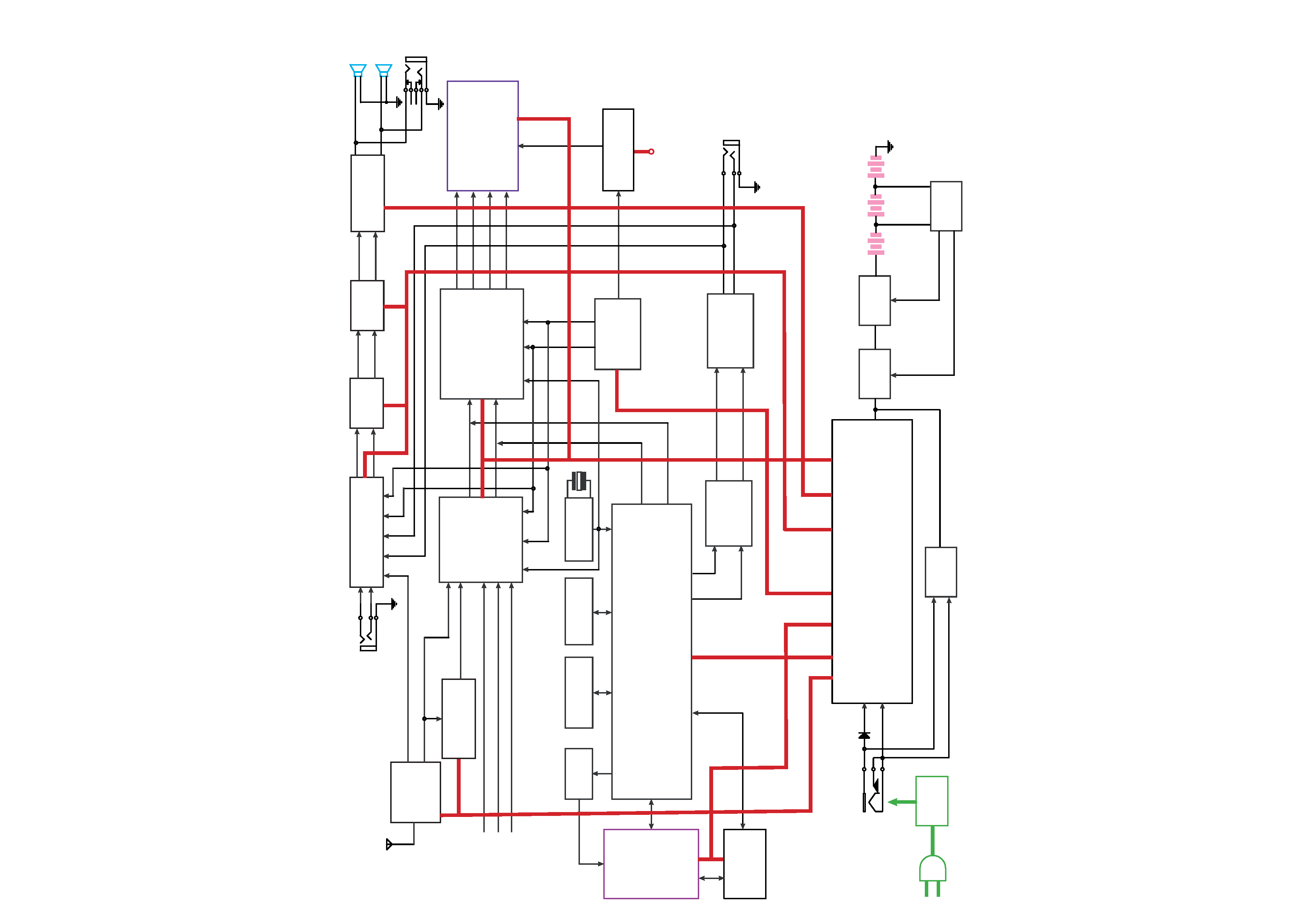
OVERALL BLOCK DIAGRAM
AC
Adapter
DC IN +15V
DC / DC
MB3813
UPA1716
UPA1716
110~240V
50/60Hz
BATTERY
DV23
PU mechanism
DRIVER
(BA5954FP)
16M FlashROM
MX29LV160ABTC-70
64M SDRAM
NT56V6620COT-75S
TC4W53
27MHz
AUDIO D/A
(PCM1742)
TFT MONITOR
AUDIO AMP
(NJM4558)
74HCU04
27MHz
Video IN
AUDIO OUT
SPEAKER LOUT
SPEAKER ROUT
L
R
L
R
D-terminal IN
DC 15V
OSCILLATOR
OZ960
VIDEO DECODER
TW9908
TW8803
CPU D1850
TV PCB
Z86229
MSP3450
4558
TPA6011A4
ZA3020/TPS60400/PQ05DZ11
BA033/UPC29M05/PQ03EZ11
S8253B
Audio IN
PHONE OUT
S-video IN
ANT
4558
DVD5V
+5V/-5V
AMP5V
TV5V
DVD3.3V
TFT3.3V
L
R
Audio
TV Video
CPU5V
5V
+5V/-5V
+5V/-5V