
CORDLESS TELEPHONE
SERVICE MANUAL
FILE NO. 2B0-9907
FT-8859
PUBLISHED IN JAPAN, Oct., 1999

1
CONTENTS
SAFETY PRECAUTIONS ........................................................................................................................... 1
OPERATING CONTROLS .......................................................................................................................... 2
ALIGNMENT PROCEDURE ....................................................................................................................... 3
BLOCK DIAGRAMS.................................................................................................................................... 9
SCHEMATIC DIAGRAMS ......................................................................................................................... 11
TROUBLESHOOTING HINTS .................................................................................................................. 16
IC AND TRANSISTOR VOLTAGE CHART ................................................................................................ 23
SEMICONDUCTOR LEAD IDENTIFICATION........................................................................................... 28
ELECTRICAL PARTS LOCATION............................................................................................................. 30
WIRING DIAGRAMS................................................................................................................................. 33
EXPLODED VIEW AND MECHANICAL PARTS LIST .............................................................................. 36
PARTS LIST .............................................................................................................................................. 40
ASSEMBLY PARTS LIST .......................................................................................................................... 54
SPECIFICATIONS..................................................................................................................................... 55
SAFETY PRECAUTIONS
Before returning any models to the customer, a safety check of the entire instrument should be made.
The service technician must be sure that no protective device built into the instrument by the
manufacture has become defective or inadvertently degraded during servicing.
1.WARNING:
Alterations of the design or circuitry of these models should not be made.
Any design changes or additions such as, but not limited to, circuit modifications, auxiliary speaker
jacks, switches, grounding, active or passive circuitry, etc. may alter the safety characteristics of these
models and potentially create a hazardous situation for the user.
Any design alterations or additions will void the manufacturer's warranty and will further relieve the
manufacturer of responsibility for personal injury or property damage resulting therefrom.
2.PRODUCT SAFETY NOTICE
Many electrical and mechanical parts in this chassis have special characteristics. These
characteristics often pass unnoticed and the protection afforded by them cannot necessarily be
obtained by using replacement components rated for higher voltage, wattage, etc. Replacement parts
that have these special safety characteristics are identified in this manual and its supplements;
electrical components having such features are identified by a
in the schematic diagram and the
parts list. Before replacing any of these components, read the parts list in this manual carefully. The
use of substitute replacement parts that do not have the same safety characteristics as specified in the
parts list may create shock, fire or other hazards.
2
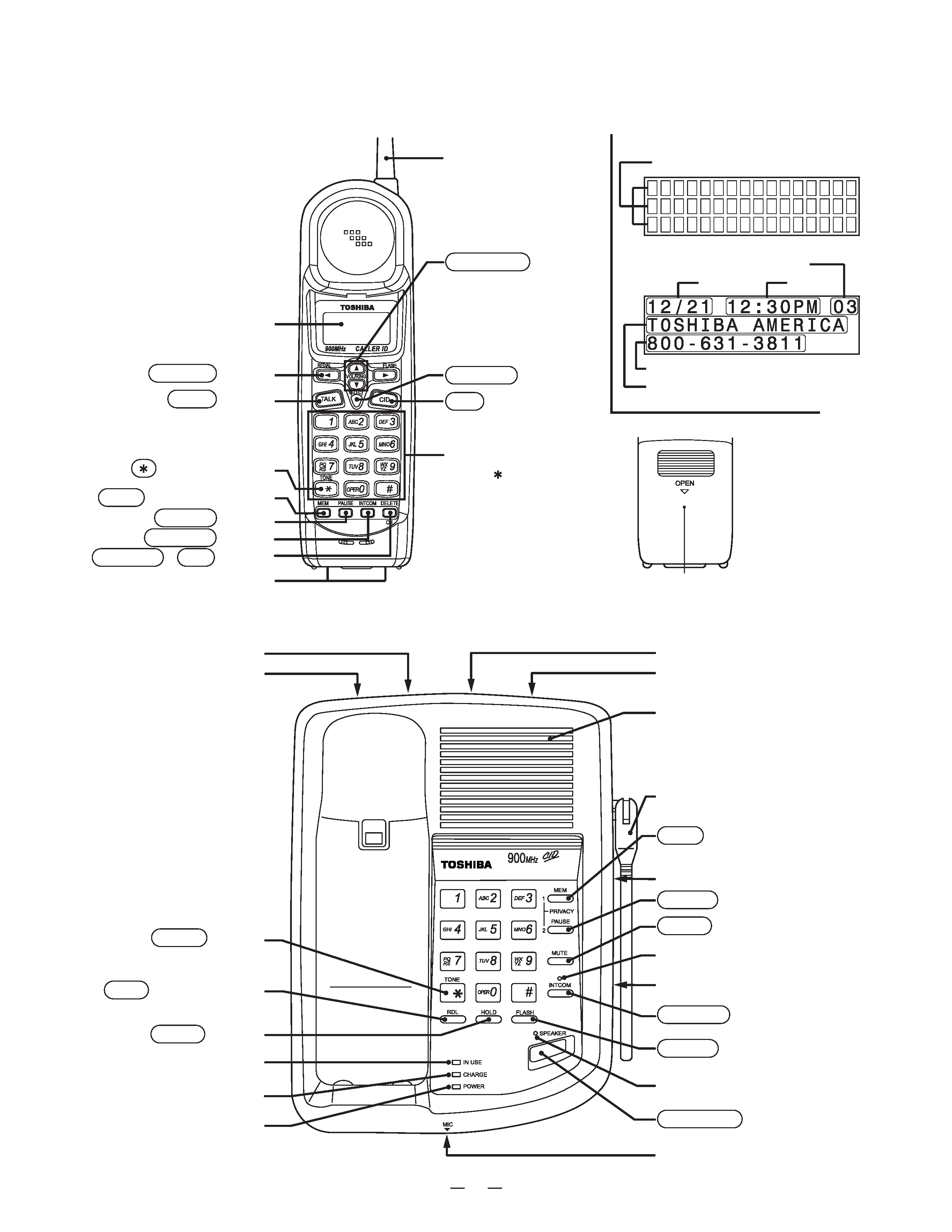
Dot matrix display
Number of calles
Date
Time
Caller's telephone number
Caller's name
TONE/PULSE Switch
Line Ringer Volume Switch
Speaker
Antenna
MEM (Memory) Button
Speed Dial Index (1 to 10)
PAUSE Button
MUTE Button
INTCOM LED (Green)
Speaker Volume Control
INTCOM Button
FLASH Button
Speaker LED (Green)
SPEAKER Button
Microphone
DC 9V IN Jack
VOL/RING Button
SELECT Button
CID (Caller ID) Button
Battery compartment
Dialpad
(0~9,
and # buttons)
Liquid Crystal Display
(LCD)
REDIAL Button
TALK Button
(TONE) Button
MEM (Memory) Button
PAUSE Button
INTCOM Button
DELETE , CH Button
Charging contacts
TEL Line Jack
TONE Button
RDL (Redial) Button
HOLD Button
IN USE LED
CHARGE LED
POWER LED
Antenna
ALL DIGITAL CALLER ID
CORDLESS TELEPHONE
FT8859
OPERATING CONTROLS
HANDSET CONTROLS AND FUNCTIONS
LCD
BASE UNIT CONTROLS AND FUNCTIONS
3
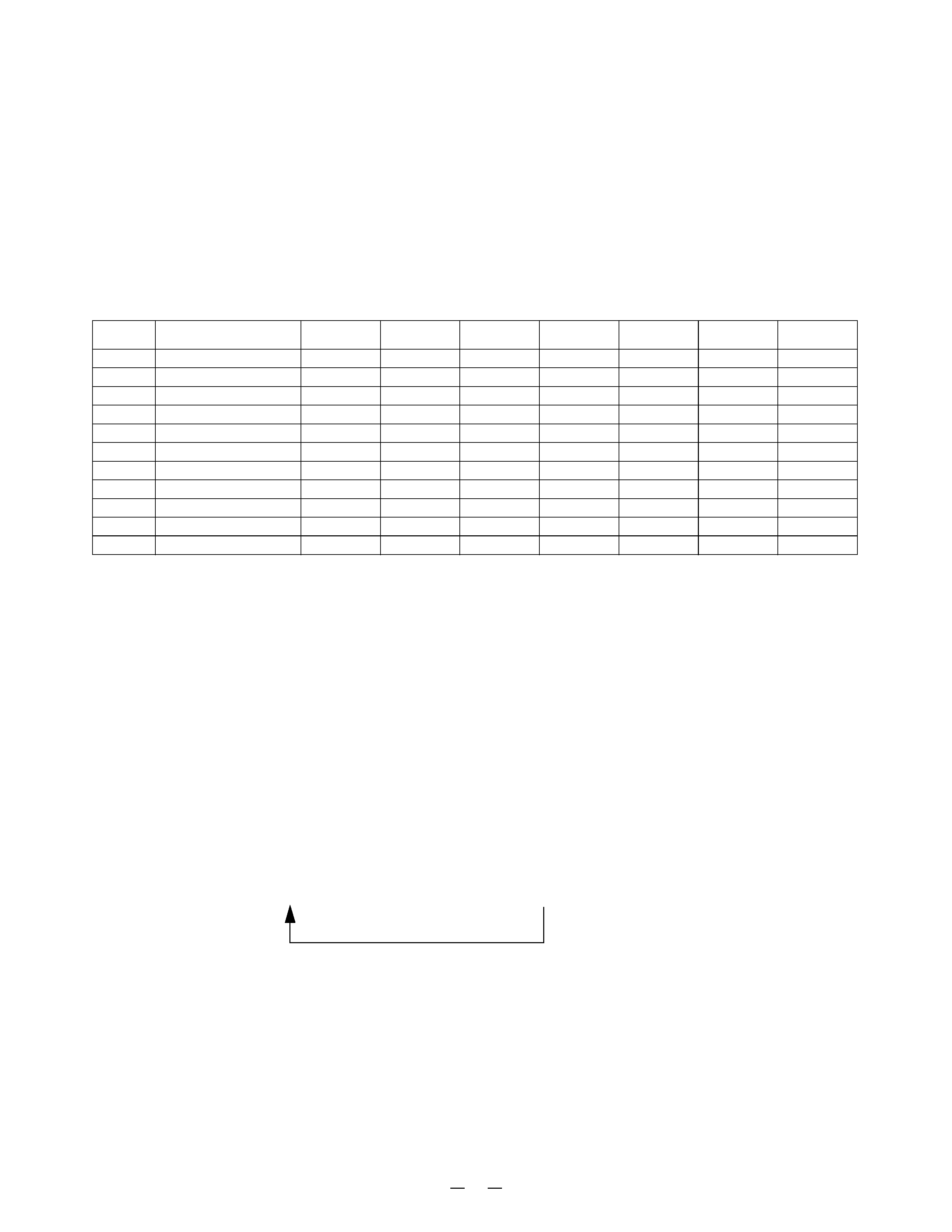
ALIGNMENT PROCEDURE
Test Mode For Base Unit
Press the "
" and "#" keys at the same time about 2 seconds while turning the power on, the confirmation beep
will sound to indicate that the unit is in the test mode.
1. To change the TEST mode:
Press the number key for the corresponding TEST mode.
(Refer to the following table)
2. To change channel:
Press the "RDL" key, but if changing the step, the channel returns to the start
channel.
3. To cancel Test mode:
Bell rings (except for Step 6), charge the Handset (except for Step 9) or Power
off.
*1 : "0000..." (250Hz) will be fed out continuously as transmitting data.
*2 : Bell rings and INTCOM LED lights when sensing SQ.
-6#= (YHU\#SXVKLQJ#RI#)/$6+#NH\#PDNHV#WRQH#FKDQJH1#+,Q#WKH#FDVH#RI#'XDO#7RQH/#FKDQJHV#DV
4Ö5Ö6Ö7Ö8Ö9Ö:Ö;Ö<Ö3ÖÖ&Ö41,
DTMF Frequency
ROW1
:
697
ROW2
:
770
ROW3
:
852
ROW4
:
941
COL1
:
1209
COL2
:
1336
COL3
:
1477
*4 : Bell rings when the received data are "0000..." (250Hz).
*5 : Charge LED lights when detecting Charge ON.
Channel rotation
4<#Ö53Ö54Ö73Ö4Ö5Ö6Ö7Ö81111111111116:Ö6;Ö6<Ö73
STEP
FUNCTION
KEY
START CH
TX CONT
TX MUTE
RX MUTE
RL CONT
REMARKS
1
VO/TX FRQ. ADJ
1
19
LLLL
2
TX MODE CHECK
2
19
L
H
L
H
3
TX DATA
3
19
LLLL
*1
4
RX SENS.
4
19
H
L
H
H
5
SQ SENS.
5
19
L
L
H/L
H
*2
6
RING CHECK
6
19
H
L
L
L
7
DUAL TONE CHECK
7
19
H
L
L
H
*3
8
DATA IN CHECK
8
19
L
L
L
H
*4
9
CHANNEL DATA CHECK
9
19
H
LLL
*5
10
DUPLEX
0
19
L
H
H
H
11
INT COM
MEM
19
L
H
H
L
4
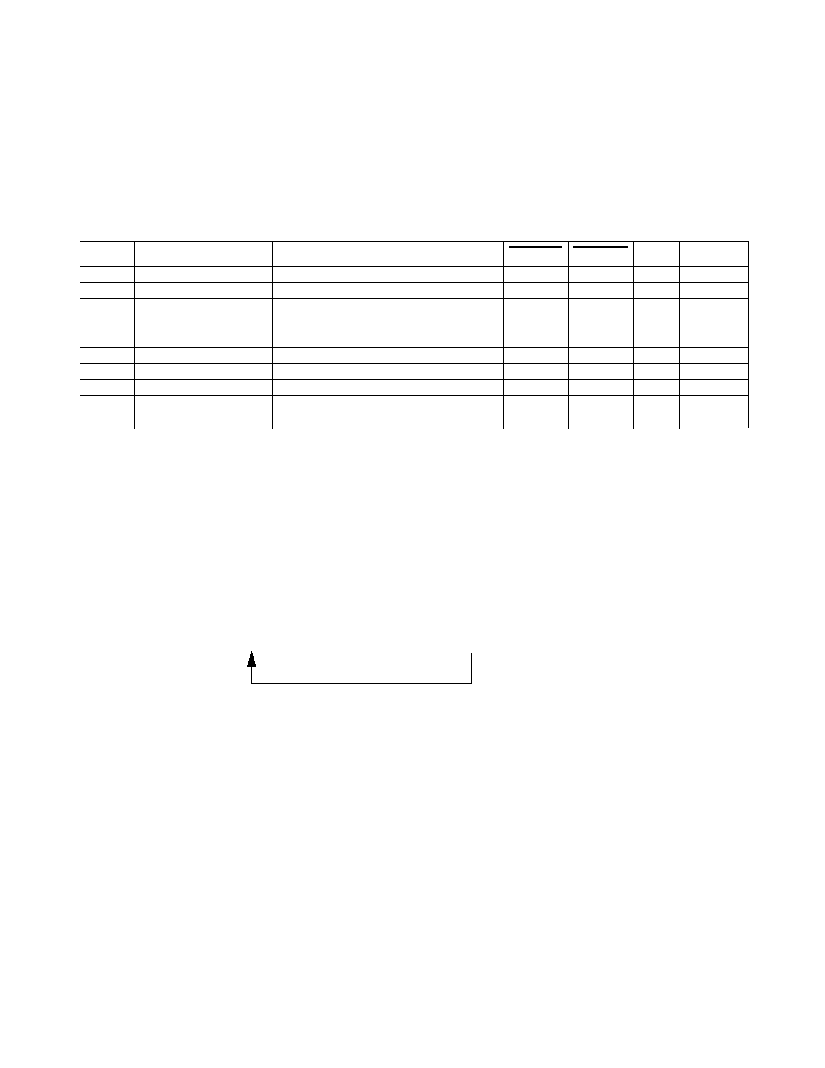
Test Mode For Handset Unit
7R#SHUIRUP#WKH#7(67#PRGH/#WXUQ#WKH#SRZHU#21#E\#SUHVVLQJ#WKH#³ ´#DQG#³&´#EXWWRQV#DW#WKH#VDPH#WLPH1
When entered the TEST mode, the bell rings and the unit enters TEST mode 1. (Refer to the following table.)
1. To change the TEST mode:
Press the number key for the corresponding TEST mode.
(Refer to the following table)
2. To change channel:
Press "CH" key.
(Note: If the step is changed, the channel returns to the start channel.)
3. To cancel the Test mode:
Turn the power OFF, charge the Handset, or press the "TALK" key.
*A : Squelch ON is H, or Squelch OFF is L.
*1 : In the TEST mode 3, "0000..." will be fed out continuously as transmitting data.
*2 : In the TEST mode 6, bell (1kHz) rings when the data received is "0000...".
*3 : In the TEST mode 7, bell rings with initial 2 tone (2kHz, 2.2kHz).
*4 : In the TEST mode 8, bell (1kHz) rings when P_BATLOW is "L".
*5 : In the TEST mode 9, bell rings when P_CHRGIN is "L".
Channel rotation
54#Ö53Ö4<Ö73Ö4Ö5Ö6Ö7Ö81111111111116:Ö6;Ö6<Ö73
STEP
FUNCTION
KEY
START CH TX CONT
SC
TX MUTE RX MUTE CONV REMARKS
1
VO/TX FRQ. ADJ
1
21
L
H
L
L
H
2
TX MOD. CHECK
2
21
L
H
H
L
L
3TX DATA
3
21
L
H
L
L
L
*1
4
RX SENS.
4
21
H
H
L
H
L
5SQ SENS.
5
21
L
H
L
*A
L
6
RECEIVE DATA CHECK
6
21
L
H
L
L
H
*2
7
BELL
7
21
H
L
L
L
H
*3
8
BATTERY LOW CHECK
8
21
H
L
L
L
H
*4
9
CHARGE CHECK
9
21
H
L
L
L
H
*5
10
DUPLEX
0
21
L
H
H
H
L