
SERVICE MANUAL
Projection Television
62HM95
FILE NO. 020-200510
(REVISED. 3)
Published in Japan Oct. 2005 (YC)
TOSHIBA CORPORATION 2005

- 2 -
TABLE OF CONTENTS
SAFETY INSTRUCTIONS .............................................................................................................................................. 3
SERVICE MODE ............................................................................................................................................................ 4
SETTING & ADJUSTING DATA ...................................................................................................................................... 9
LAMP UNIT REPLACEMENT ....................................................................................................................................... 10
PARTS REPLACEMENT IN LIGHT ENGINE.................................................................................. .............................
13
LIGHT ENGINE REPLACEMANT.................................................................................................................................
15
EXPLODED VIEW ........................................................................................................................................ ................ 17
MECHANICAL DISASSEMBLY .................................................................................................................................... 18
CHASSIS REPLACEMENT PARTS LIST ..................................................................................................................... 19
PC BOARDS TOP AND BOTTOM VIEW ..................................................................................................................... 28
TERMINAL VIEW OF TRANSISTORS ......................................................................................................................... 48
CIRCUIT BLOCK DIAGRAM ........................................................................................................................................ 53
APPENDIX:
CIRCUIT DIAGRAM

- 3 -
Many electrical and mechanical parts in this chassis have special safety-related characteristics. These characteristics are
often passed unnoticed by a visual inspection and the protection afforded by them cannot necessarily be obtained by using
replacement components rated for higher voltage, wattage, etc. Replacement parts which have these special safety charac-
teristics are identified in this manual and its supplements; electrical components having such features are identified by the
international hazard symbols on the schematic diagram and the parts list.
Before replacing any of these components, read the parts list in this manual carefully. The use of substitute replacement
parts which do not have the same safety character istics as specified in the parts list may create shock, fire, or other hazards.
PRODUCT SAFETY NOTICE
SAFETY INSTRUCTIONS
WARNING: Service should not be attempted by anyone unfamiliar with the necessary precautions on this receiver.The following
are the necessary precautions to be observed before servicing this chassis.
1. An isolation transformer should be connected in the power line between the receiver and the AC line before any service is
performed on the receiver.
2. When replacing a chassis in the cabinet, always be certain that all the prospective devices are put back in place, such as;
non-metallic control knobs, insulating covers, shields, isolation resistor-capacitor network etc.
SAFETY PRECAUTION
- 4 -
3. SELECTING THE ADJUSTING ITEMS
1) Every pressing of CHANNEL
button in the service mode changes the adjustment items in the order of table-2.
(
button for reverse order)
Refer to table-1 for preset data of adjustment mode.
(See SETTING & ADJUSTING DATA on page 9)
4. ADJUSTING THE DATA
1) Pressing of VOLUME
or
button will change the value of data in the range from 00H to FFH. The variable range
depends on the adjusting item.
5. EXIT FROM SERVICE MODE
1) Pressing POWER button to turn off the TV once.
SERVICE MODE
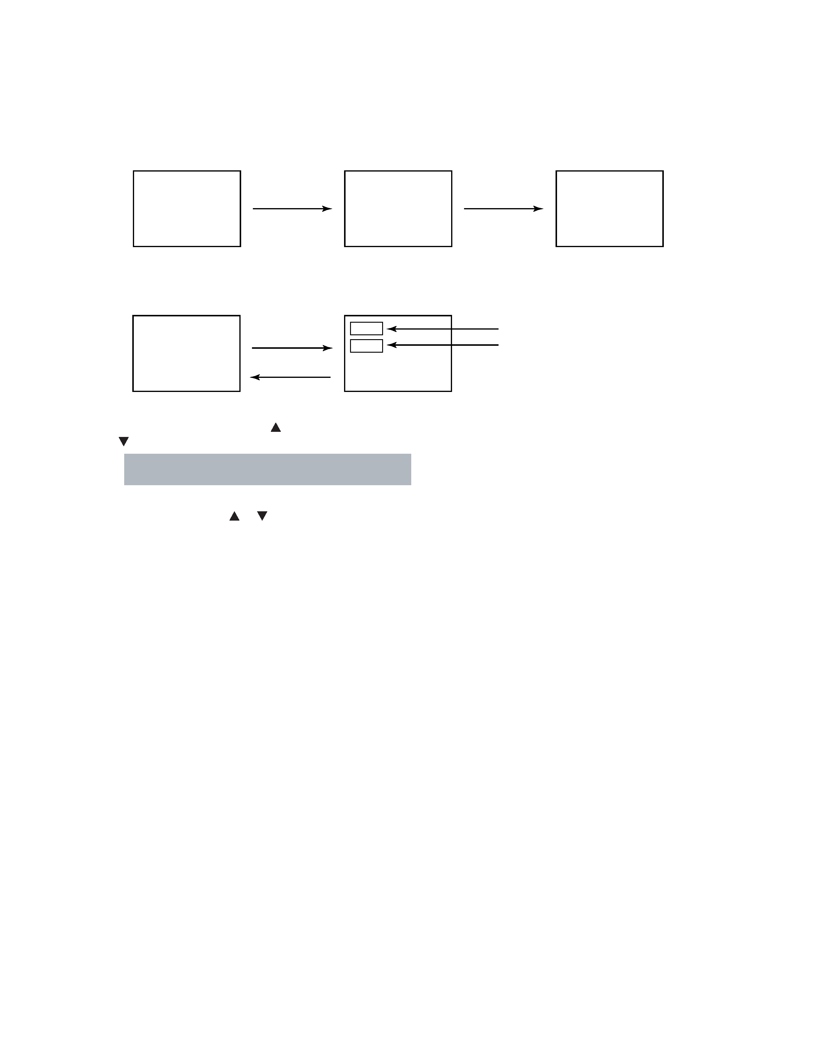
1. ENTERING SERVICE MODE
MUTE
S
(Service mode display)
3) While pressing the MUTE button,
press MENU button on TV set.
2) Press MUTE button
again and keep pressing.
1) Press MUTE button twice
on Remote Control.
2. DISPLAYING THE ADJUSTMENT MENU
Adjustment mode
Press
Press
Service mode
Item
Data
S
1) Press MENU button on Remote Control.
- 5 -
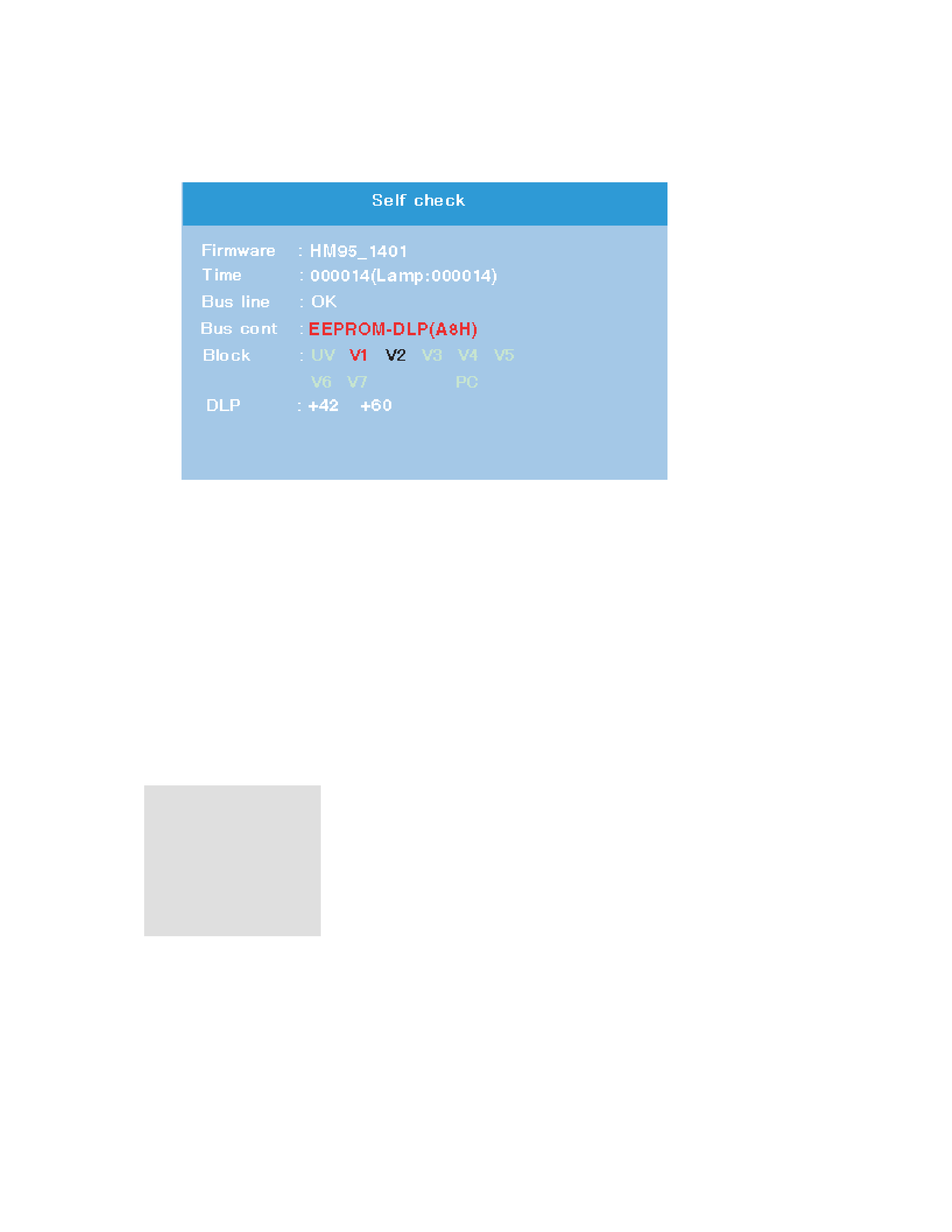
6. SELF DIAGNOSTIC FUNCTION
1)
Press "9" button on Remote Control during display of adjustment menu in the service mode.
The diagnosis will begin to check if interface among IC's is executed properly.
2)
During diagnosis, the following displays are shown.
1 Firmware :
Version information of microprocessor
In case of file name :
HM95 and Version : 1401 indicates[HM95_1401].
2 Time : Total brightness hour of the projection lamp. (Unit : H)
3
4
Bus line : --"OK" is normal
"SCL-GND"(Red indication) : SCL-GND short circuit
"SDA-GND"(Red indication) : SDA-GND short circuit
"SCL-SDA"(Red indication) : SCL-SDA short circuit
5
Bus cont : --- "OK" is normal.
NG is abnormal(Red indication).
When type name of semiconductor indicates.
6
Block
UV : TV reception mode
V1 : VIDEO 1 input mode
V2 : VIDEO 2 input mode
V3 :
VIDEO 3 input mode
V4 :
ColorStream HD-1 IN
1
2
3
4
5
6
V
5 : ColorStream HD-2 IN
V
6 : HDMI IN 1
V
7 : HDMI IN 2
microprocessor into the unit.
DLP : Thermal sensor values information that indicates both of nearby the projection lamp and DMD