FILE NO. 023-200222
SERVICE MANUAL
SUMMARY
N2PSP Chassis
COLOR TELEVISION
PUBLISHED IN JAPAN,
Aug., 2002
So
50HDX82, 57HDX82
(TAC0274)
50HDX82, 57HDX82 are the same as 65HDX82 except for the parts tabled on back of this sheet.
Use this service manual together with the service manual of 65HDX82 (File No. 020-200218).
(TAC0273)
TOSHIBA CORPORATION
1-1, SHIBAURA 1-CHOME, MINATO-KU, TOKYO 105-8001, JAPAN
REPLACEMENT PARTS LIST DIFFERENCES
Location
No.
Part No.
Description
A001
23411548
Wood Cabinet (50HDX82)
A001
23411713
Wood Cabinet (57HDX82)
A102
23527179
Speaker Grille (50HDX82)
A102
23527193
Speaker Grille (57HDX82)
A175
23929314
Bezel Clip
A201
23540542
Bezel (50HDX82)
A201
23540677
Bezel (57HDX82)
A424
23540544
Back Board (50HDX82)
A424
23540679
Back Board (57HDX82)
A501
23728011
Screw
A701
23064539
Carton (50HDX82)
A701
23064866
Carton (57HDX82)
A703
23946194
Packing, Top (50HDX82)
A703
23946191
Packing, Top (57HDX82)
A708
23946189
Packing, Bottom (50HDX82)
A708
23946190
Packing, Bottom (57HDX82)
H001
23321447
Tuner, EL977LW
K501
23311957
Lenti Sheet, SCREEN50KM-L
(50HDX82)
K501
23311955
Lenti Sheet, SCREEN57DM-L
(57HDX82)
K502
23311958
Fresnel Sheet, SCREEN50KM-F
(50HDX82)
Location
No.
Part No.
Description
K502
23311956
Fresnel Sheet, SCREEN57DM-F
(57HDX82)
K503
23311858
Screen Protector,
SCR-PRO50WAL (50HDX82)
K503
23311857
Screen Protector, SCR-PRO57AL
(57HDX82)
K601
23405012
MIRROR50WL (50HDX82)
K601
23405028
Mirror (57HDX82)
* U901
23787889
SIGNAL/CONV Board, PD0639L
(50HDX82)
* U901
23787890
SIGNAL/CONV Board, PD0639M
(57HDX82)
* UH01
23787644
DIGI-CONV Board, PD0638C
(50HDX82)
* UH01
23787711
DIGI-CONV Board, PD0638E
(57HDX82)
* V901R
23086799
Protector Coupling R (50HDX82)
* V901R
23086411
Protector Coupling R (57HDX82)
* V902G
23086800
Protector Coupling G (50HDX82)
* V903B
23086801
Protector Coupling B (50HDX82)
* V903B
23086412
Protector Coupling B (57HDX82)
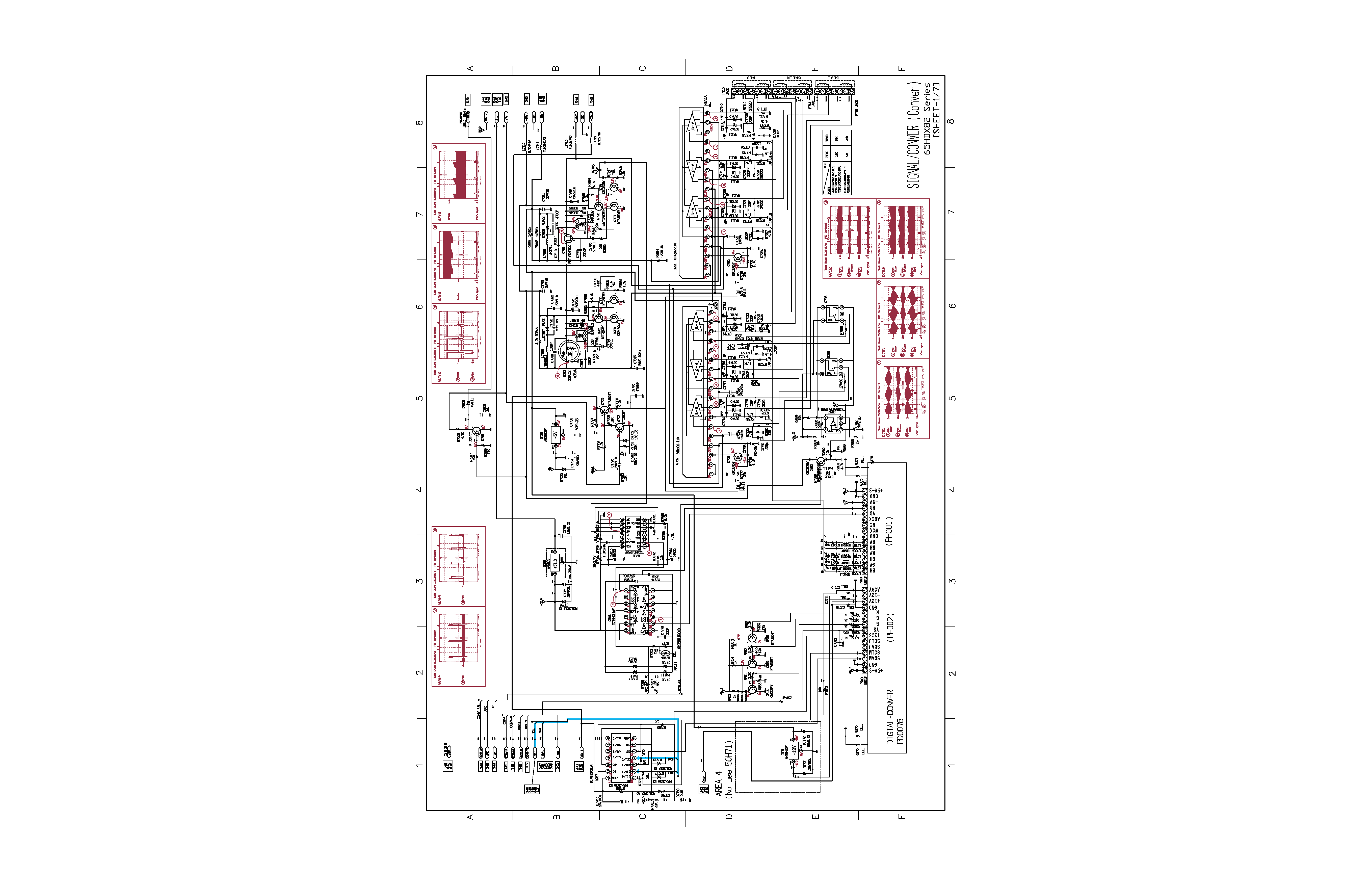
SCHEMATIC DIAGRAM
WARNING: BEFORE SERVICING THIS CHASSIS, READ THE "X-RAY RADIATION PRECAUTION", "SAFETY
PRECAUTION" AND "PRODUCT SAFETY NOTICE" ON THE MANUAL FOR THIS MODEL.
CAUTION: The international hazard symbols "*" in the schematic diagram and the parts list designate components
which have special characteristics important for safety and should be replaced only with types identical to those in the
original circuit or specified in the parts list. The mounting position of replacements is to be identical with originals.
Before replacing any of these components, read carefully the PRODUCT SAFETY NOTICE on the MANUAL for this
model. Do not degrade the safety of the receiver through improper servicing.
NOTE:
1. RESISTOR
Resistance is shown in ohm [K = 1.000, M = 1.000.000]. All resistors are 1/6W and 5%
tolerance carbon resistor, unless otherwise noted as the following marks.
1/2R = Metal or Metal oxide of 1/2 watt
1/2S = Carbon compsistion of 1/2 watt
1RF = Fuse resistor of 1 watt
10W = Cement of 10 watt
K =
±10%
G =
±2%
F =
±1%
2. CAPACITOR
Unless otherwise noted in schematic, all capacitor values less than 1 are expressed in
?F, and the values more than 1 in pF.
All capacitors are ceramic 50V, unless otherwise noted as the following marks.
Electolytic capacitor
Mylar capacitor
3. The parts indicated with " * " have special characteristics, and should be replaced with identical parts only.
4. Voltages read with DIGITAL MULTI-METER from point indicated to chassing ground, using a color bar signal with all
controls at normal, line voltage 120 volts.
5. Waveforms are taken receiving color bar signal with enough sensitivity.
6. Voltage reading shown are nominal values and may vary
±20% except H.V.
MODEL : 65HDX82
66
SCHEMATIC DIAGRAM STRUCTURE:
SIGNAL / CONVER Circuit
( Conver )
[ SHEET - 1/7 ] ...................... 1/19
( Defrection )
[ SHEET - 2/7 ] ...................... 2/19
( If )
[ SHEET - 3/7 ] ...................... 3/19
( Maicon )
[ SHEET - 4/7 ] ...................... 4/19
( Power )
[ SHEET - 5/7 ] ...................... 5/19
( Audio )
[ SHEET - 6/7 ] ...................... 6/19
( Video )
[ SHEET - 7/7 ] ...................... 7/19
POWER / DEF Circuit
( Power )
[ SHEET - 1/2 ] ...................... 8/19
( Defrection )
[ SHEET - 2/2 ] ...................... 9/19
DPC Circuit ........................................................................................................... 10/19
DIGITAL CONVER Circuit
( 1/2 )
[ SHEET - 1/2 ] .................... 11/19
( 2/2 )
[ SHEET - 2/2 ] .................... 12/19
AV / REM Circuit
( 1/2 )
[ SHEET - 1/2 ] .................... 13/19
( 2/2 )
[ SHEET - 2/2 ] .................... 14/19
FRONT / T. FOCUS-SENSOR Circuit ................................................................. 15/19
SRS-WOW Circuit ................................................................................................. 16/19
CRT / SVM Circuit
( CRT )
[ SHEET - 1/2 ] .................... 17/19
( SVM )
[ SHEET - 2/2 ] .................... 18/19
DVI Circuit ............................................................................................................. 19/19
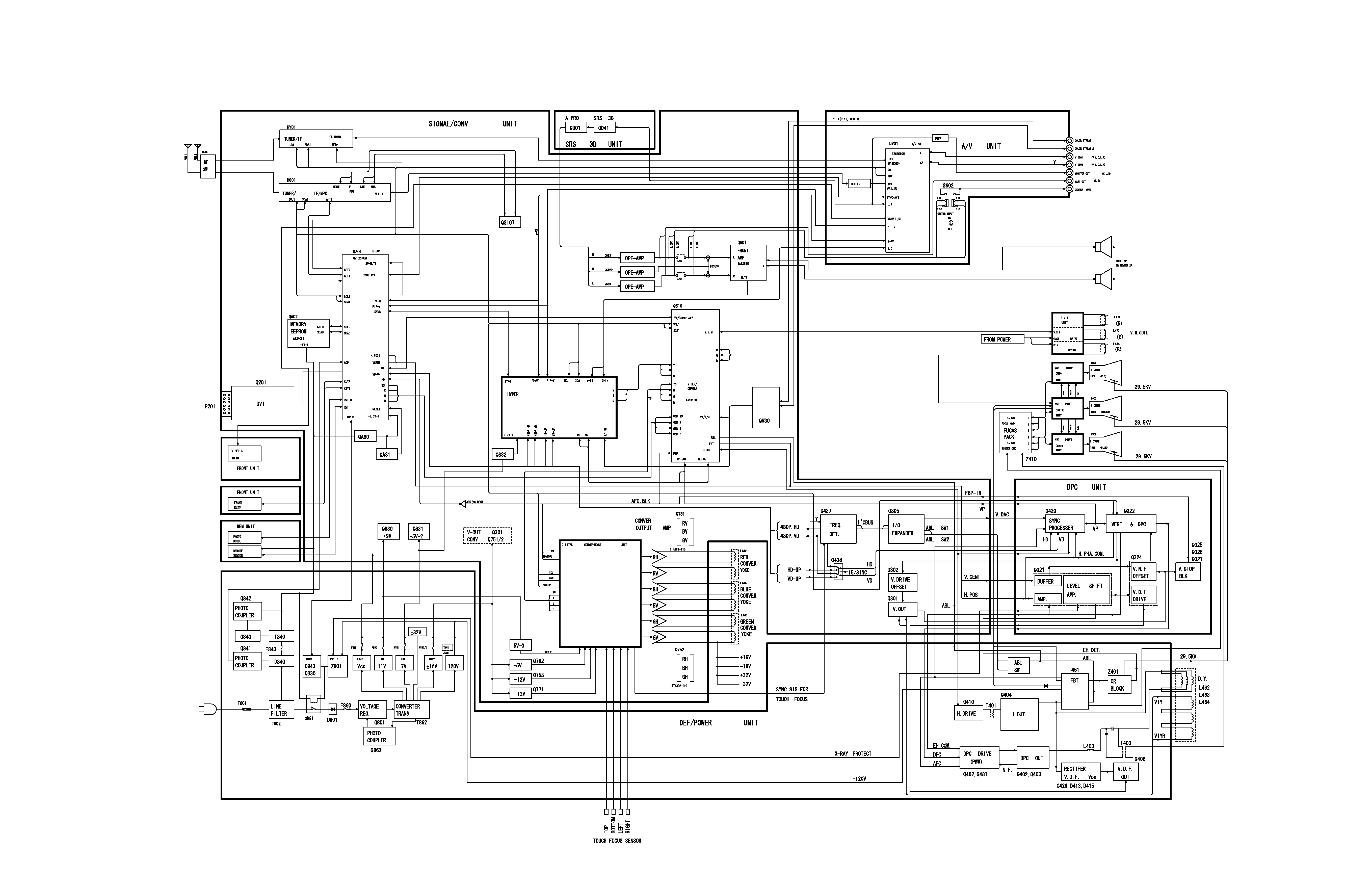
CIRCUIT BLOCK DIAGRAM
67
68
65HDX82
BLOCK DIAGRAM