
- 1 -
SERVICE MANUAL
Projection Television
44HM85
FILE NO. 050-200534
Published in Japan, Sep. 2005 (YC)
TOSHIBA CORPORATION 2005

- 2 -
TABLE OF CONTENTS
SAFETY PRECAUTIONS ........................................................................................................................................................... 3
SPECIFICATIONS ....................................................................................................................................................................... 4
DESCRIPTION OF CONTROLS ................................................................................................................................................. 5
ADJUSTMENT INSTRUCTION ................................................................................................................................................ 12
EXPLODED VIEW .................................................................................................................................................................... 16
REPLACEMENT PARTS LIST .................................................................................................................................................. 17
PC BOARDS TOP & BOTTOM VIEW ....................................................................................................................................... 32
BLOCK DIAGRAM .................................................................................................................................................................... 39
SCHEMATIC DIAGRAM ............................................................................................................................................................ 43
- 3 -
SAFETY PRECAUTIONS
General Guidance
An lsolation Transformer should always be used during the
servicing of a receiver whose chassis is not isolated from the
AC power line. Use a transformer of adequate power rating as
this protects the technician from accidents resulting in personal
injury from electrical shocks.
It will also protect the receiver and it's components from being
damaged by accidental shorts of the circuitary that may be
inadvertently introduced during the service operation.
If any fuse (or Fusible Resistor) in this monitor is blown, replace
it with the specified.
When replacing a high wattage resistor (Oxide Metal Film
Resistor, over 1W), keep the resistor 10mm away from PCB.
Keep wires away from high voltage or high temperature parts.
Leakage Current Cold Check(Antenna Cold Check)
With the instrument AC plug removed from AC source, connect
an electrical jumper across the two AC plug prongs.
Place the AC switch in the on positioin, connect one lead of
ohm-meter to the AC plug prongs tied together and touch other
ohm-meter lead in turn to each exposed metallic parts such
as antenna terminals, phone jacks, etc.
If the exposed metallic part has a return path to the chassis,
the measured resistance should be between 1M
and 5.2M.
When the exposed metal has no return path to the chassis
the reading must be infinite.
An other abnormality exists that must be corrected before the
receiver is returned to the customer.
IMPORTANT SAFETY NOTICE
Many electrical and mechanical parts in this chassis have special safety-related characteristics. These parts are identified
by in
the Schematic Diagram and Replacement Parts List.
It is essential that these special safety parts should be replaced with the same components as recommended in this
manual to prevent Shock, Fire, or other Hazards.
Do not modify the original design without permission of manufacturer.
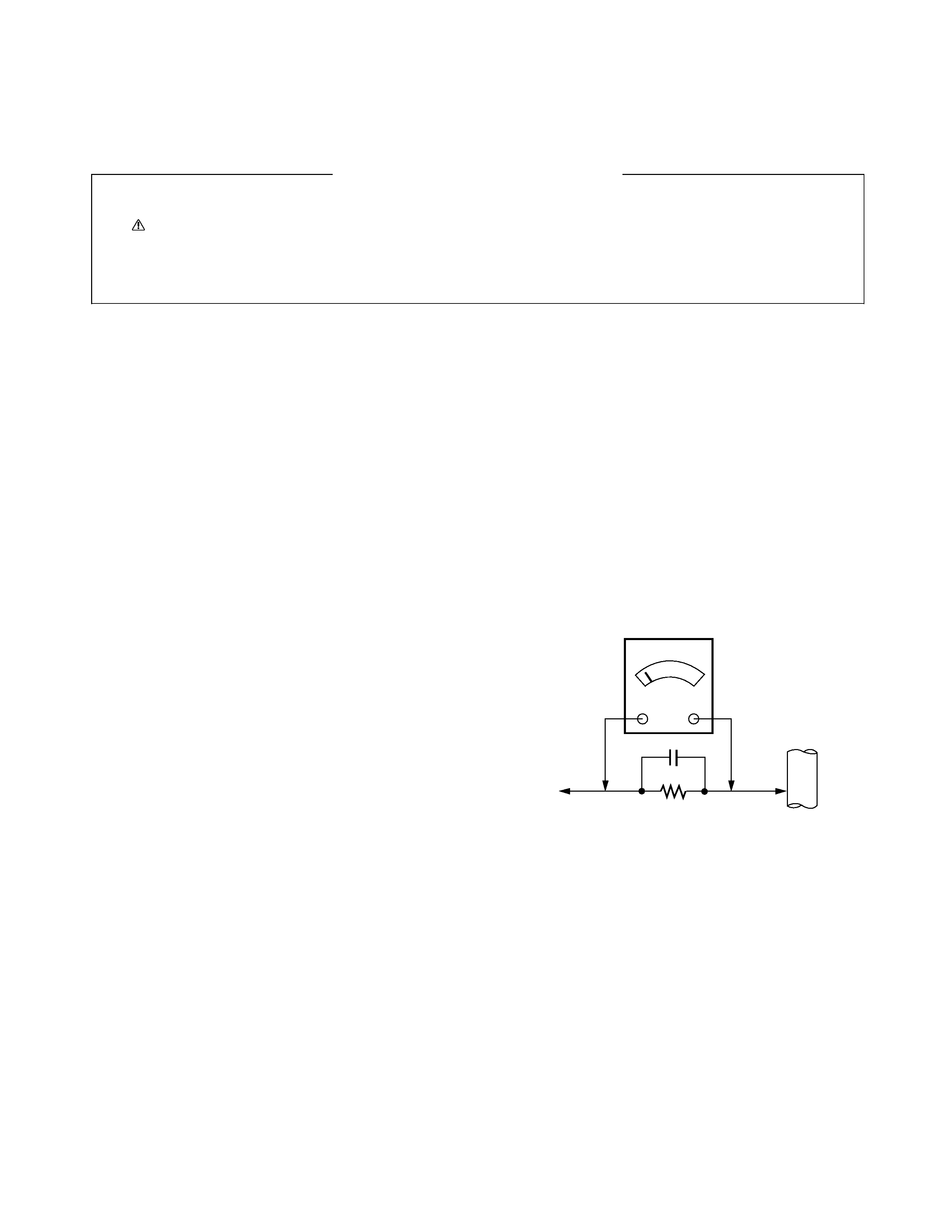
Leakage Current Hot Check (See below Figure)
Plug the AC cord directly into the AC outlet.
Do not use a line Isolation Transformer during this
check.
Connect 1.5K/10watt resistor in parallel with a 0.15uF capacitor
between a known good earth ground (Water Pipe, Conduit, etc.)
and the exposed metallic parts.
Measure the AC voltage across the resistor using AC
voltmeter with 1000 ohms/volt or more sensitivity.
Reverse plug the AC cord into the AC outlet and repeat AC
voltage measurements for each esposed metallic part. Any
voltage measured must not exceed 0.75 volt RMS which is
corresponds to 0.5mA.
In case any measurement is out of the limits sepcified, there
is possibility of shock hazard and the set must be checked
and repaired before it is returned to the customer.
Leakage Current Hot Check circuit
TOSHIBA OF CANADA LTD.
191 McNABB STREET, MARKHAM.
ONTARIO, L3R 8H2, CANADA
TEL : (905)470-5400
1.5 Kohm/10W
To Instrument's
exposed
METALLIC PARTS
Good Earth Ground
such as WATER PIPE,
CONDUIT etc.
AC Volt-meter
0.15uF

- 4 -
Product Specifications
Model
44HM85
Horizontal Size (Inches)
39.9
Height (Inches)
29.2
Depth (Inches)
14.3
Weight (lbs.)
56.2
Power Requirement
AC 120V, 60Hz
Television System
American TV Standard, NTSC, ATSC with STB
Television Channels
VHF: 2 - 13
UHF: 14 - 69
CATV: 1 - 125
Power Consumption (W)
210W
Antenna
75 ohm External Terminal for VHF/UHF
Audio Output (W)
15W x 2
External Input/Output Ports
A/V input (3 set)
Monitor out (1 set)
S-Video input (3)
COLORSTREAM HD input (2 set)
RGB input (1)
HDMI input (1)
RGB audio input (1 set)
UPGRADE port (1)
RF input (1)
· This model complies with the specifications listed below.
· Designs and specifications are subject to change without notice.
· This model may not be compatible with features and/or specifications that may be
added in the future.
SPECIFICATIONS
- 5 -
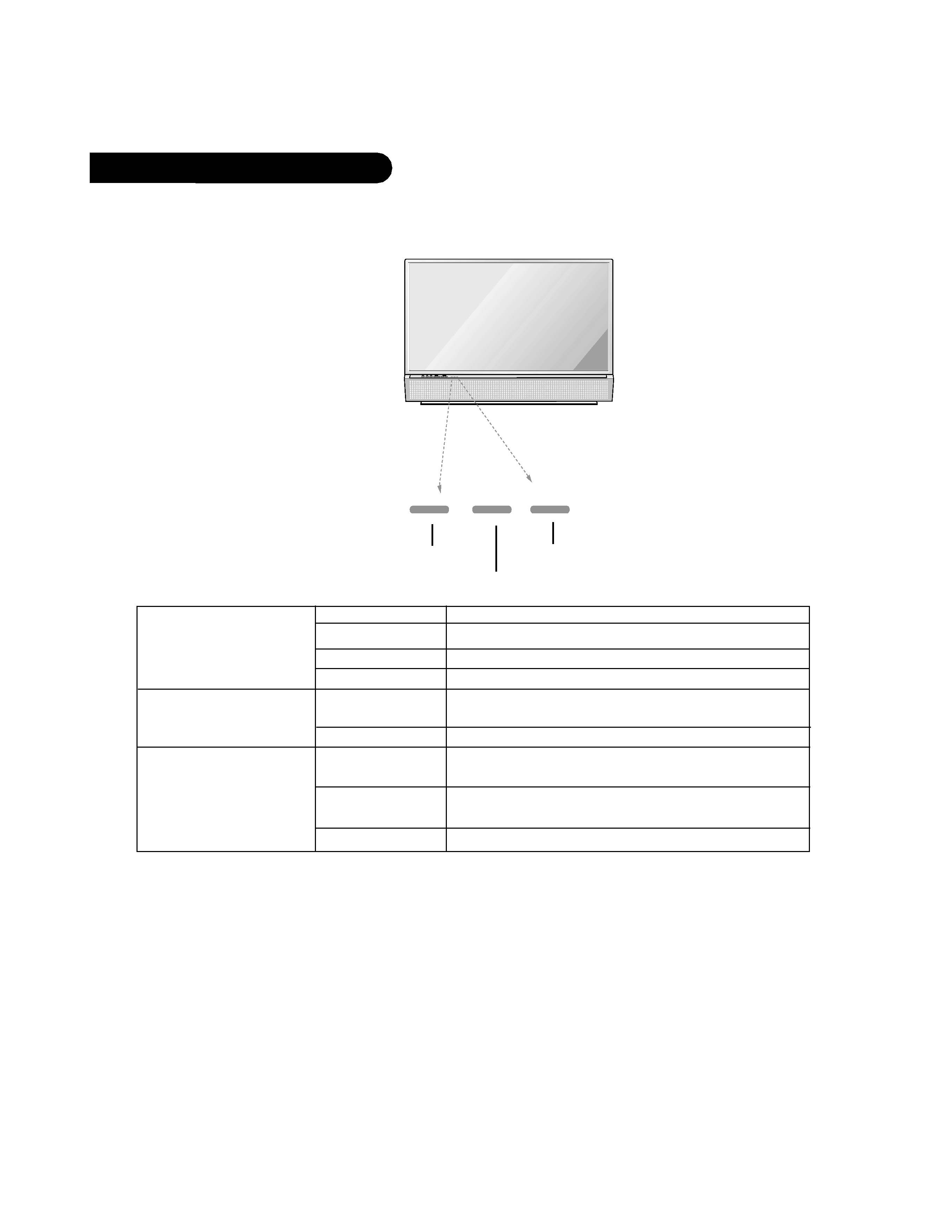
Function Status Indicators
Lamp indicator, operation indicator, and temperature indicator located below the front panel controls,
reveal the operating status of the DLP projection TV.
Operation Indicator
Lamp Indicator
Temperature Indicator
Off
Power cord is not connected.
Red
Power Cord is connected, unit is on standby mode.
Green
TV turns on.
Orange (flashing)
Preparing operation in standby mode.
Red (flashing)
There is a problem with the lamp or around it. Contact
an authorized service center.
Green (flashing)
The lamp cover is not closed.
Red
The projection TV has shut down due to overheating.
After viewing the phrase "Thermal High Error".
Red (flashing)
The projection TV shut down due to the cooling fan
trouble.
Contact an authorized service center.
Orange
Thermal warning.
Operation Indicator
Lamp Indicator
Temperature Indicator
DESCRIPTION OF CONTROLS