
SERVICE MANUAL
SUMMARY
COLOR TELEVISION
N1PSP Chassis
42H81 is the same as 50H81 except for the parts and bus data of micro-processor Convergence
adjustment and Mechanical disassembly tabled on back of this sheet.
Use this service manual together with the service manual of 50H81 (File No. 020-200109).
42H81
FILE NO. 023-200121
PUBLISHED IN JAPAN,
Aug., 2001
So
(TAC0156)
2
SETTING & ADJUSTING DATA DIFFERENCES
SERVICE MODE
ADJUSTING ITEMS AND DATA IN THE SERVICE MODE:
Table-3
Item
Name of adjustment
Preset
42H81
Remarks
* There are no adjustments in the Service mode.
3
Adjust convergence from center to circumference in order.
KEY FUNCTION IN THE CONVERGENCE ADJUSTMENT:
Up :
2 button
Selet Green color:
3 button
Left :
4 button
Blinking of cursor ON/OFF:
5 button
Right:
6 button
Adjust mode ON/OFF:
7 button
Down:
8 button
Erase Green line:
0 button
Erase Red line:
100 button
Erase Blue line:
CHRTN (ENT) button
Note:
Adjusting procedure in replacing convergence board.
1. User convergence center check. Make sure the best con-
vergence setting is about the center of adjustable range.
2. CENTERING ADJUSTMENT
3. PICTURE POSITION ADJUSTMENT
4. HIT, WID ADJUSTMENT
5. CONVERGENCE ADJUSTMENT
RCUT
40H
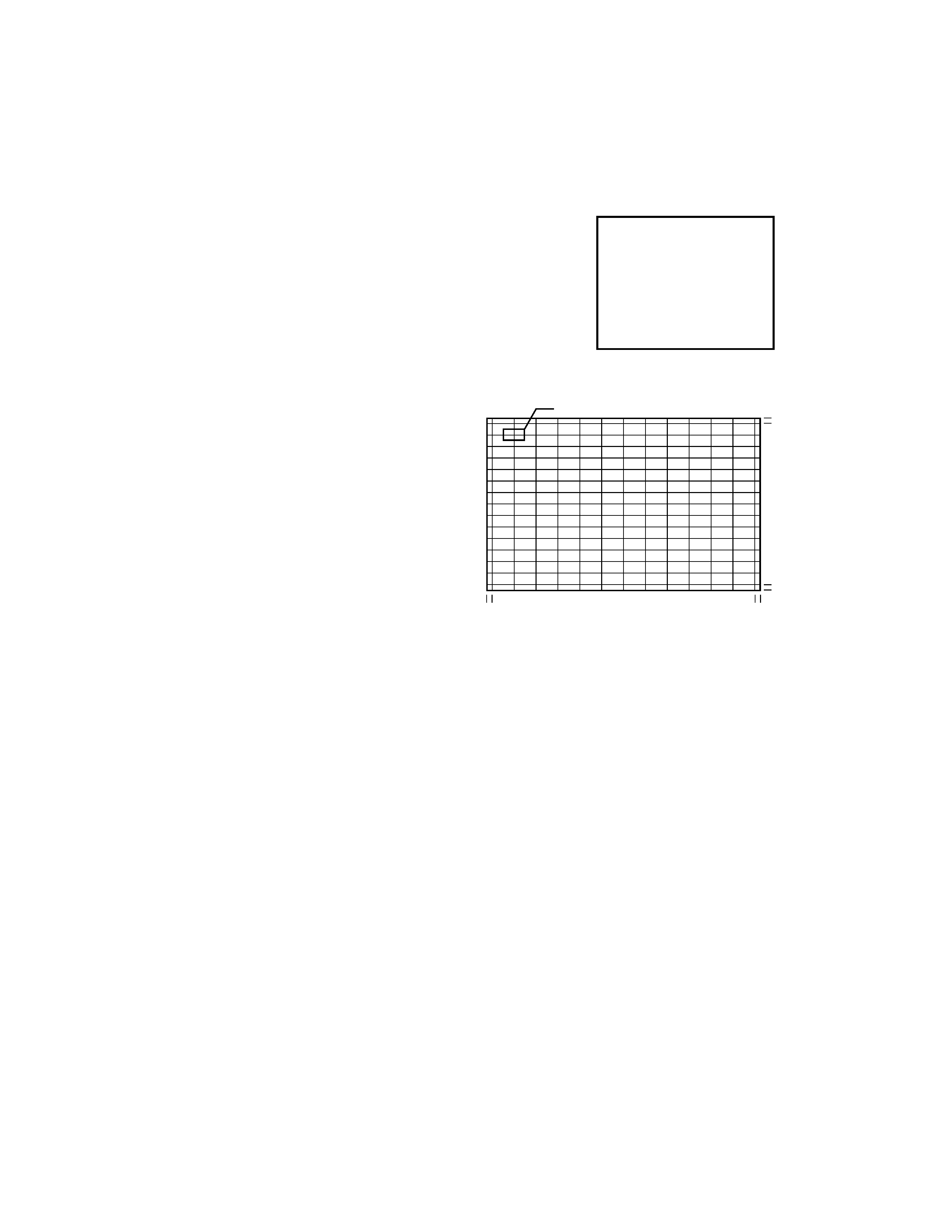
2. Press "7" button to display the built-in cross-hatch pattern.
1. Select the adjustment mode following the steps on page 9
of original service manual.
The pattern includes three colors (R, G, B).
The cursor should be blinking in Red.
This means that the Red color is adjustable.
Adjustment around cursor can be done.
3. Press "3" button to select Green color to be adjusted.
4. Press "5" button to stop the blinking of cursor.
5. Press "2 (up)", "8 (down)", "4 (left)" or "6 (right)" to obtain
the correct cross-hatch pattern as above.
If necessary, the specified color line can be erased from
the screen.
100 button ...................... to erase Red line
0 button ...................... to erase Green line
RTN (ENT) button ...................... to erase Blue line
6. Press "5" button to make the cursor blinking.
7. Press "2", "8", "4", "6" buttons to move the cursor to other
point to be adjusted.
8. Repeat steps 4 to 7.
9. Repeat steps 3 to 8 to adjust Red and Blue colors.
Converge the selected color line into the Green line.
10. Press "7" button to enter the adjusted states.
At this time, picture changes for about 1 second.
11. Press "7" button again to return to the normal picture.
CONVERGENCE ADJUSTMENT
Cursor
21.5 (42", 43")
26.5 (50")
28.5 (55")
31.0 (61")
P= 43.7
×14 (42", 43")
50.5
×14 (50")
55.8
×14 (55")
62
×14 (61")
21.5 (42", 43")
26.5 (50")
28.5 (55")
31.0 (61")
3.5 (42",43",50")
4.0 (55")
5.0 (61")
P= 72.2
×12 (42", 43")
84.0
×12 (50")
92.5
×12 (55")
102.5
×12 (61")
3.5 (42",43",50")
4.0 (53", 55")
5.0 (61")
4
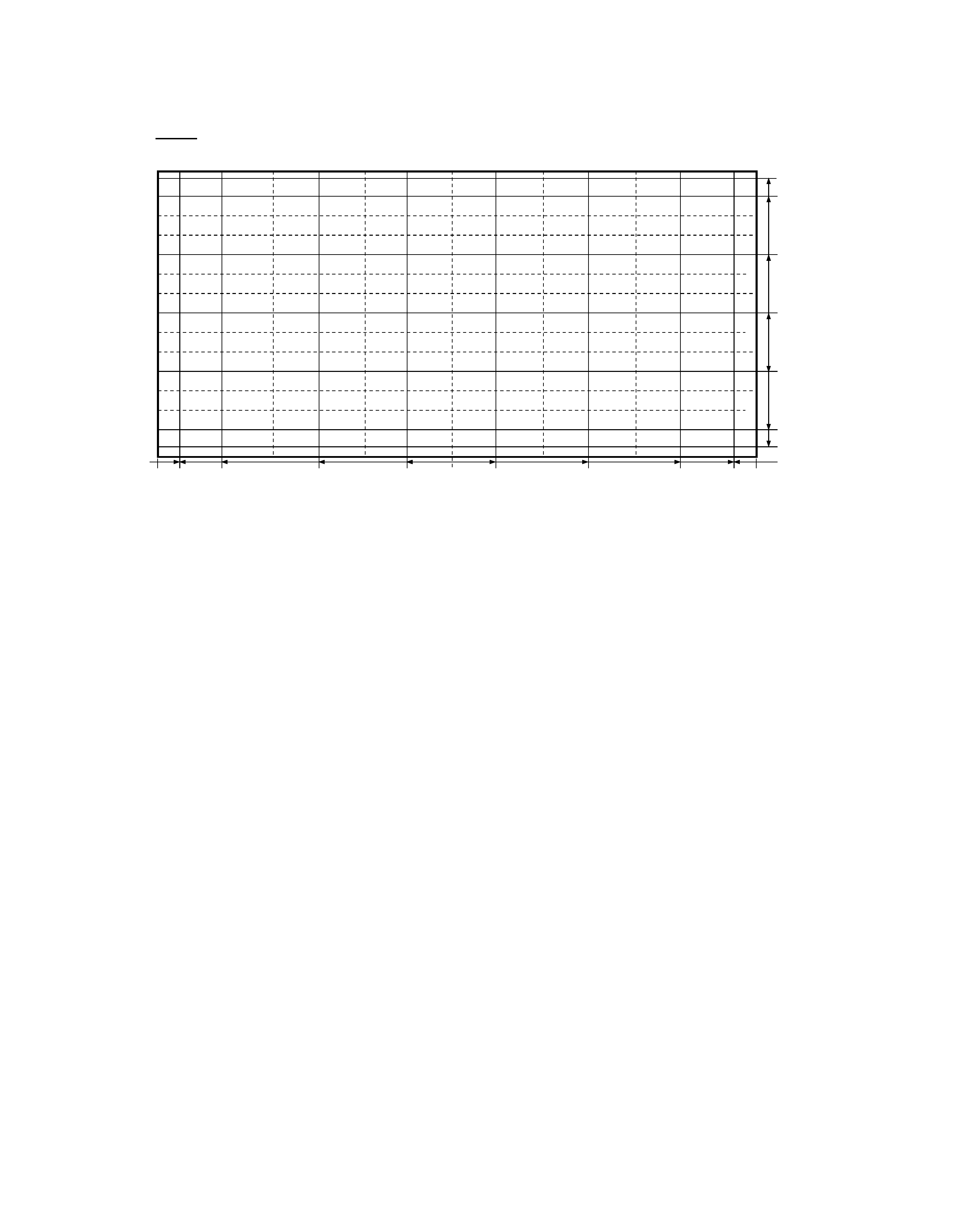
ADJUSTING DIMENSION OF EACH PICTURE SCREEN
NOTES
In many cases, color misconvergence may be corrected by returning HIT and WID data in main deflection side to initial adjusting
values. Following cases will surely require readjustment of convergence.
CRT REPLACEMENT
When CRT is replaced, main deflection readjustment and color matching are required.
Perform following procedures.
1. Replace two CRT's of blue and red.
2. Perform horizontal adjustment for blue and red yokes on base of green CRT data. Mount yoke and velocity mod. coil align-
ment, pushing towards CRT without gap.
3. Adjust alignment of blue and red. (Refer Alignment adjustment for details.)
4. Rotating centering magnet, adjust CRT centers of red and blue to CRT center of green.
(Picture position adjustment)
5. Adjust HIT and WID data of main deflection, and decide data at the most precise screen comparing to green data.
6. Adjust convergence of screen picture for color matching. Do not move green one at this time.
7. After convergence adjustment of screen picture finishes, replace green CRT.
For green CRT as well, repeat steps 2 to 5 above on bases of red and blue color matching to adjust convergence.
8. Execute TOUCH FOCUS following instructions displayed on the screen after finishing convergence adjustments of all the
colors.
Note: Press button "7" again after "PLEASE PUSH TOUCH FOCUS" has been displayed. Then, TOUCH FOCUS will not be
executed, and the current state of convergence will be displayed.
REPLACING CONVERGENCE UNIT
When replacing convergence unit, picture screen require readjustment basically, but the following method allows process be
reduced considerably.
1. Replace the memory (Q713) on defective unit with memory on new unit. Mounting the unit on the SET after the above
working realizes picture screen before replacement immediately.
2. Mount unit which has old memories, on SET and turn it on. Screen shows whole picture looks like straightly shifted towards
vertical or horizontal direction.
3. Adjust again centers of green, red and blue with centering magnets.
4. Check picture screen for slight disparity of color and picture size. If necessary, add some adjustments of main deflection and
color matching of convergence.
5. Execute TOUCH FOCUS following instructions displayed on the screen after finishing convergence adjustments of all the
colors.
Note: Press button "7" again after "PLEASE PUSH TOUCH FOCUS" has been displayed. Then, TOUCH FOCUS will not be
executed, and the current state of convergence will be displayed.
20
20.5 444.5 370.5
222.5
74.0
0
74.0
222.5
370.5
444.5
20.5
228.0
195.0
97.5
0
97.5
195.0
228.0
1:HD (1080I/NTSC) QH173, 16KB, CHIP1, UFO-*, BANK1
Vspan 32.6mm Hspan 74.0mm
42H81
42inches 16:9 Screen Size:horizontal 930mm :Vertical523mm
5
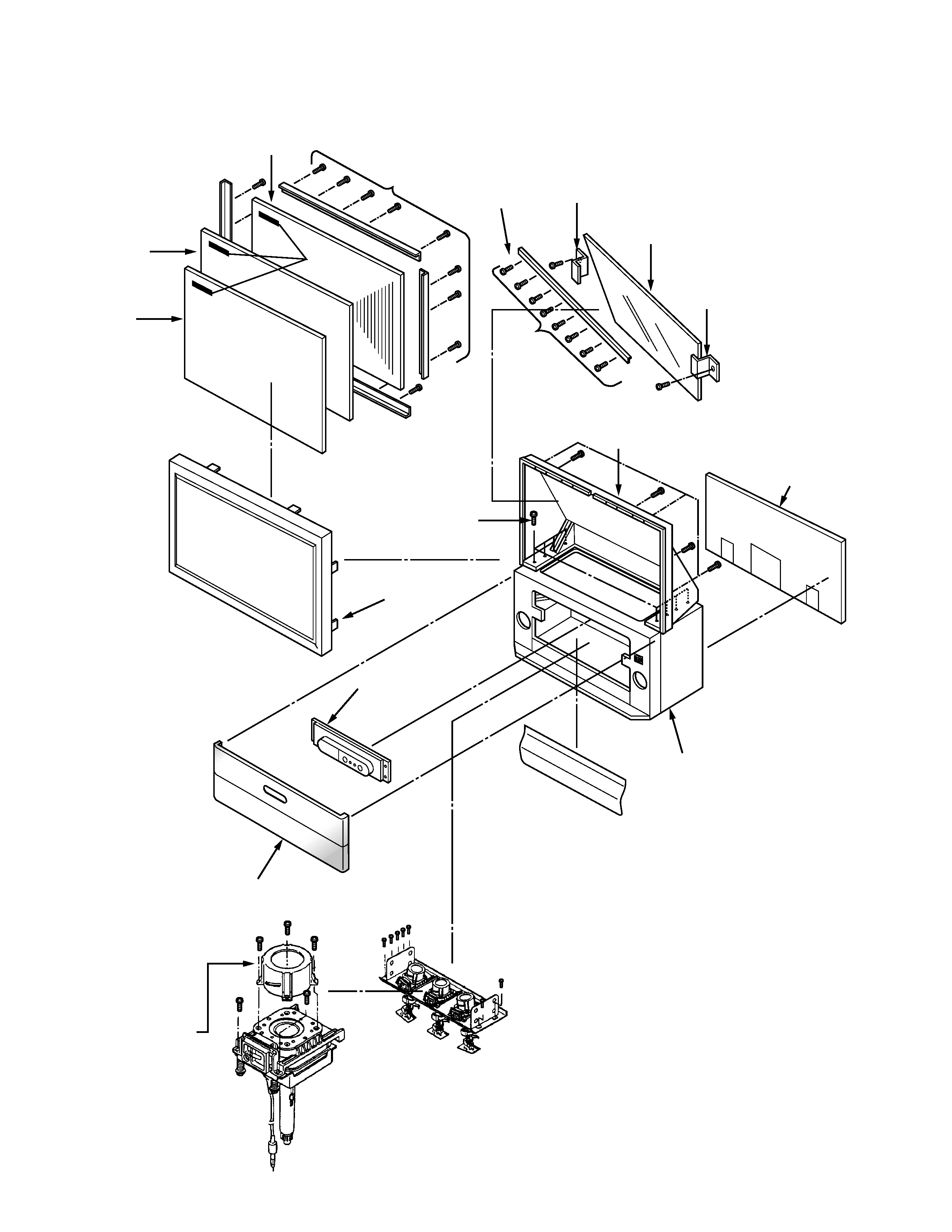
MECHANICAL DISASSEMBLY
K502
16 SCREWS
K501
K503
K601
10 SCREWS
8 SCREWS
A420
A001(A101)
A201
(A268)
A202
A214
A213
A212
A102
K111
K112
K113
6 SCREWS
8 SCREWS
A424
A262
A262
A264
SCREWS
LABELS