AD0202028C2
Compact Disc Player
SL-EH680E
Traverse Deck: RAE0152Z Mechanism series
Colour
(N)..........Glod Type
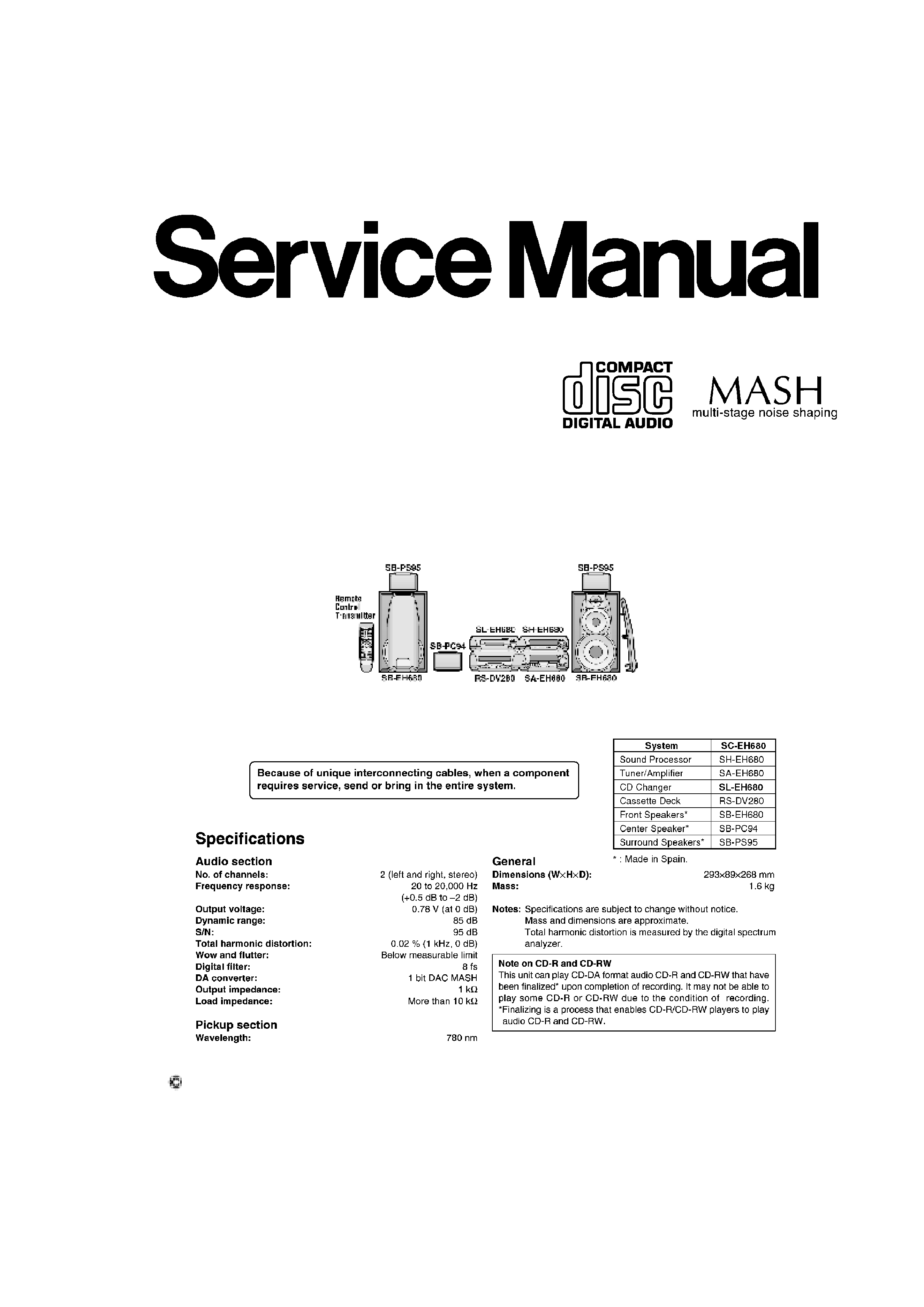
SPECIFICATIONS
2002 Matsushita Electric Industrial Co., Ltd. All rights reserved.
Unauthorized copying and distribution is a violation of law.
1
1. Note
Refer to the service manual for Model No. SA-EH680 (Order No. AD0202024C2) for information
on Accessories and Packaging.
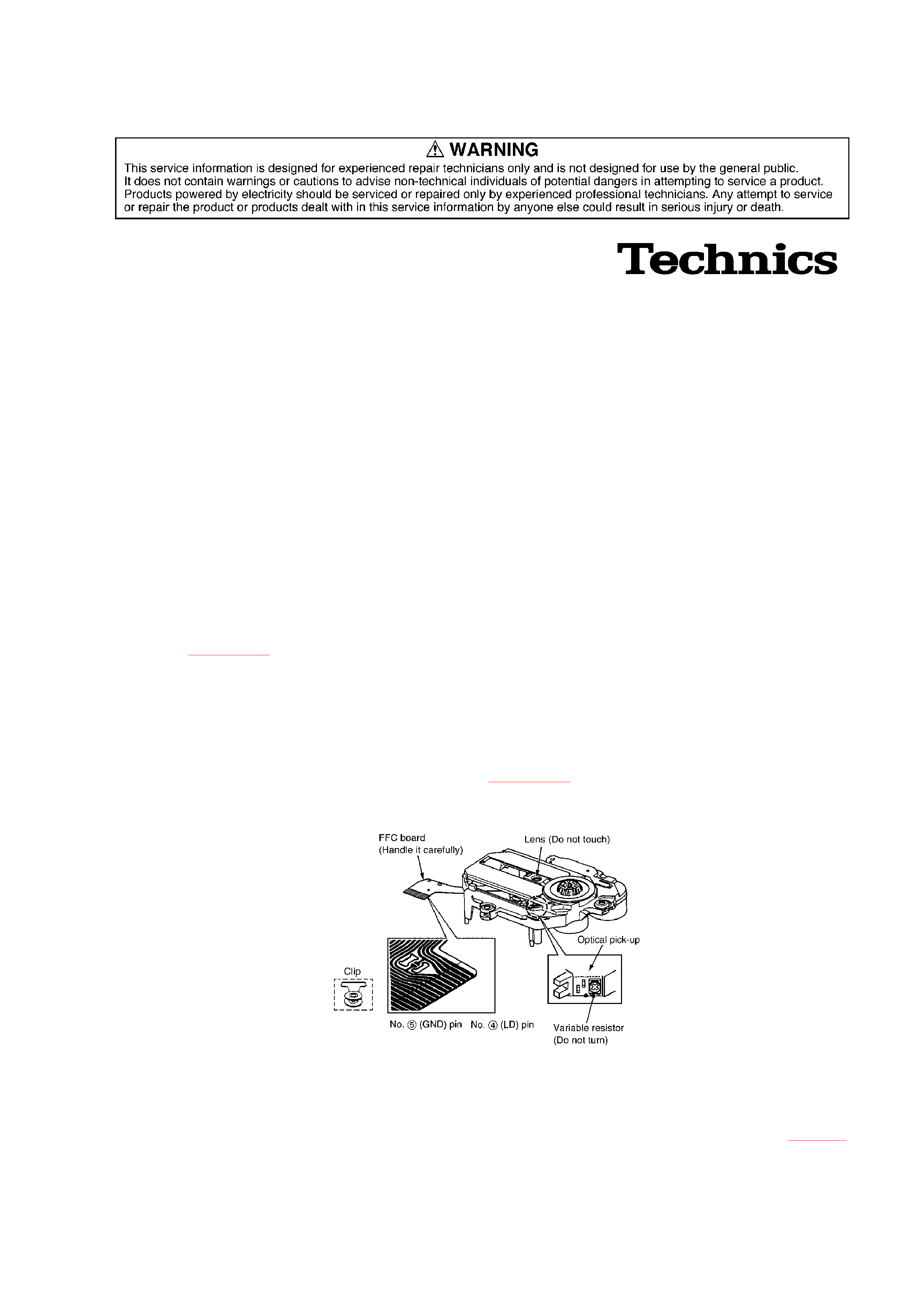
2. Handling Precautions for Traverse Deck
The laser diode in the traverse deck (optical pick-up) may break down due to potential
difference caused by static electricity of clothes or human body.
So be careful of electrostatic breakdown during repair of the traverse deck (optical pick-up).
2.1. Handling of traverse deck (optical pick-up)
1. Do not subject the traverse deck (optical pick-up) to static
electricity as it is extremely sensitive to electrical shock.
2. To protect the laser diode against electrostatic breakdown, short
the flexible board (FFC board) with a clip or similar object. Refer
to Fig. 2-1.
3. Take care not to apply excessive stress to the flexible board (FFC
board).
4. Do not turn the variable resistor (laser power adjustment). It has
already been adjusted. Refer to Fig. 2-1.
Fig. 2-1.
2.2. Grounding for electrostatic breakdown prevention
2.2.1. Human body grounding
Use the anti-static wrist strap to discharge the static electricity from your body. Refer to Fig. 2-2.
2
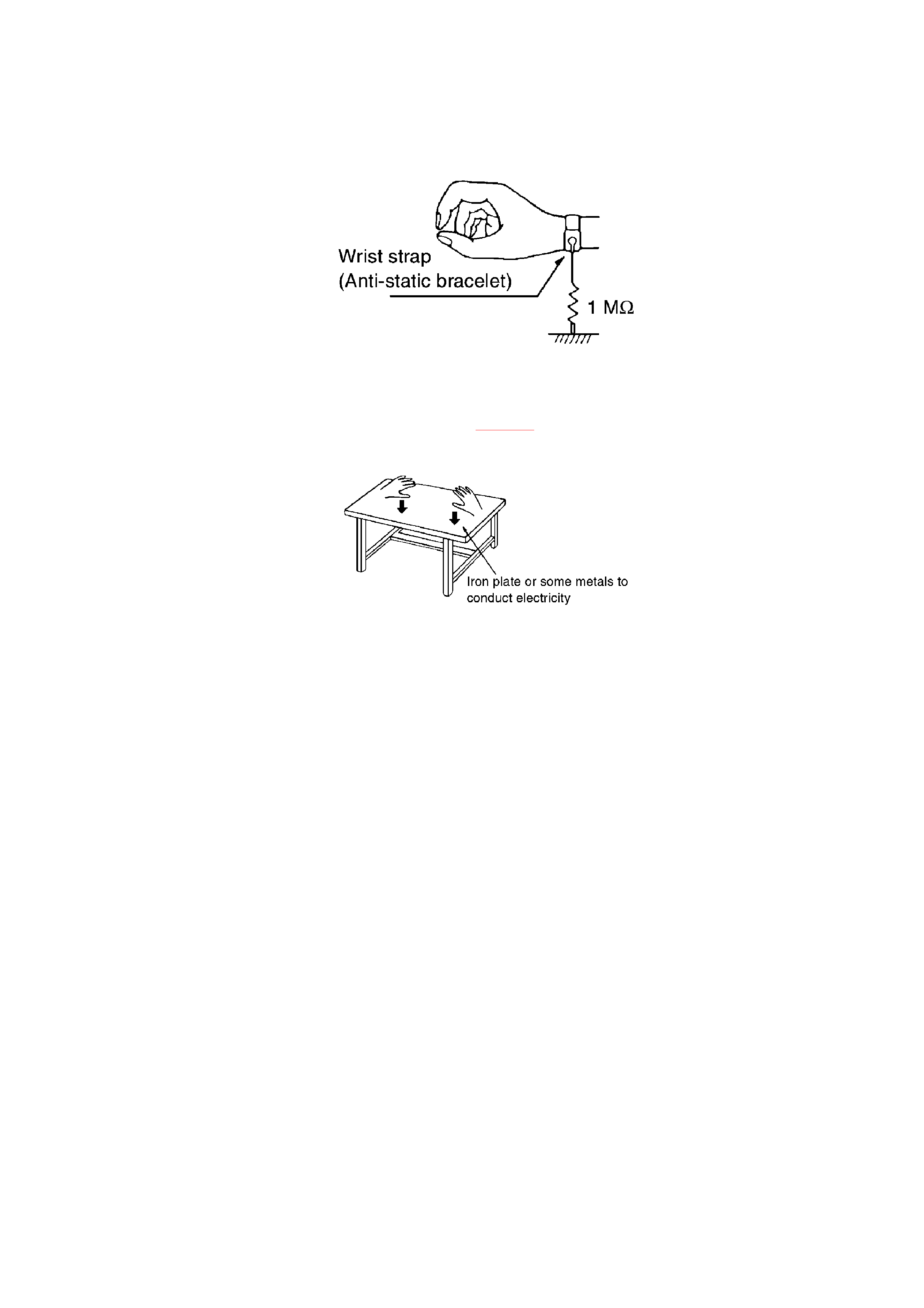
Fig. 2-2.
2.2.2. Work table grounding
Put a conductive material (sheet) or steel sheet on the area where the traverse deck (optical pick
-up) is placed, and ground the sheet. Refer to Fig. 2-3.
Fig. 2-3.
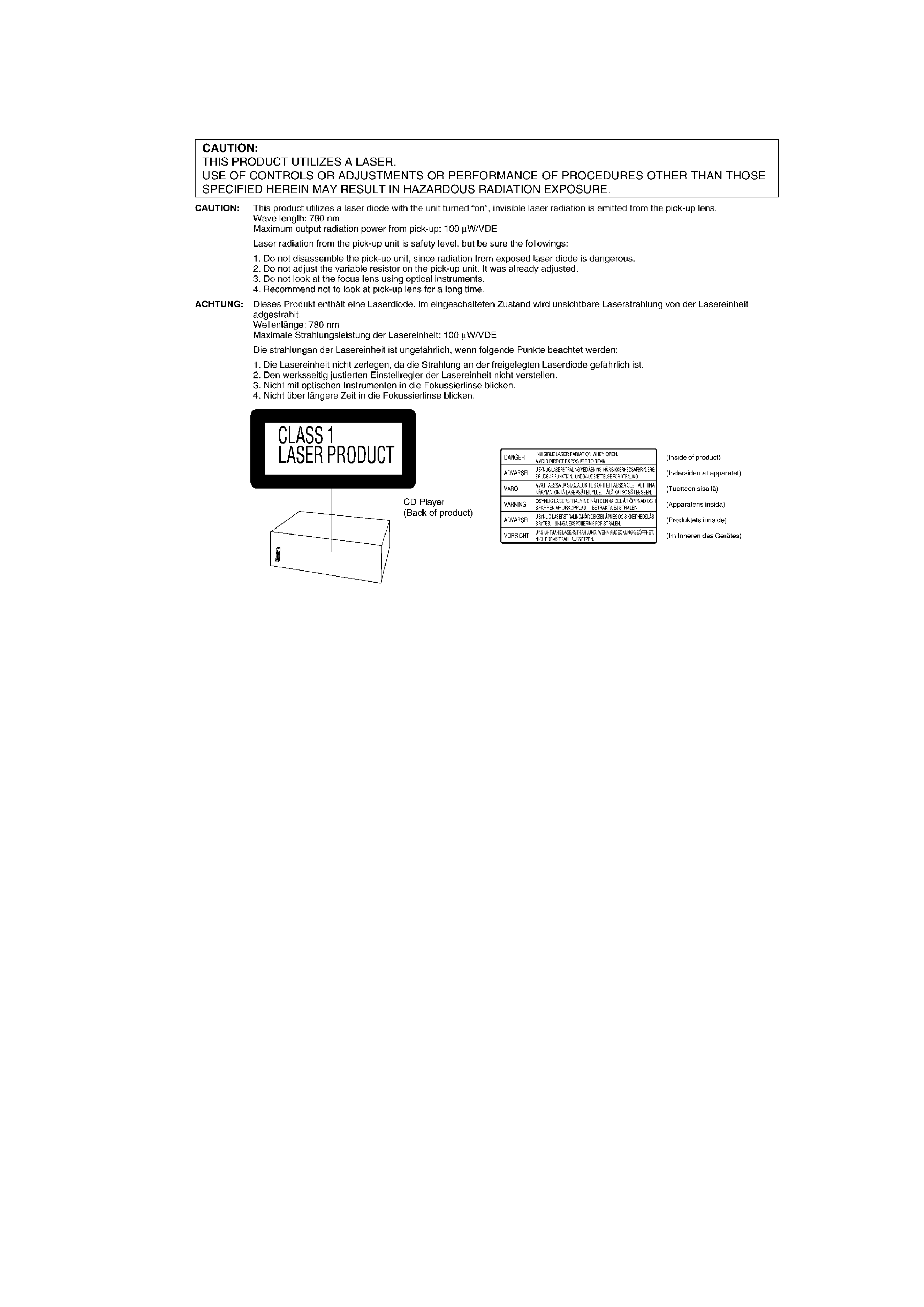
Caution:
The static electricity of your clothes will not be grounded through
the wrist strap.
So take care not to let your clothes touch the traverse deck (optical
pick-up).
3. Precaution of Laser Diode
3
4. Location of Controls
5. Operation Checks and Component Replacement /
Procedures
- This section describes procedures for checking the operation of
the major printed circuit boards and replacing the main
components.
- For reassembly after operation checks or replacement, reverse the
respective procedures. Special reassembly procedures are
described only when required.
/
5.1. Checking for the main P.C.B.
4
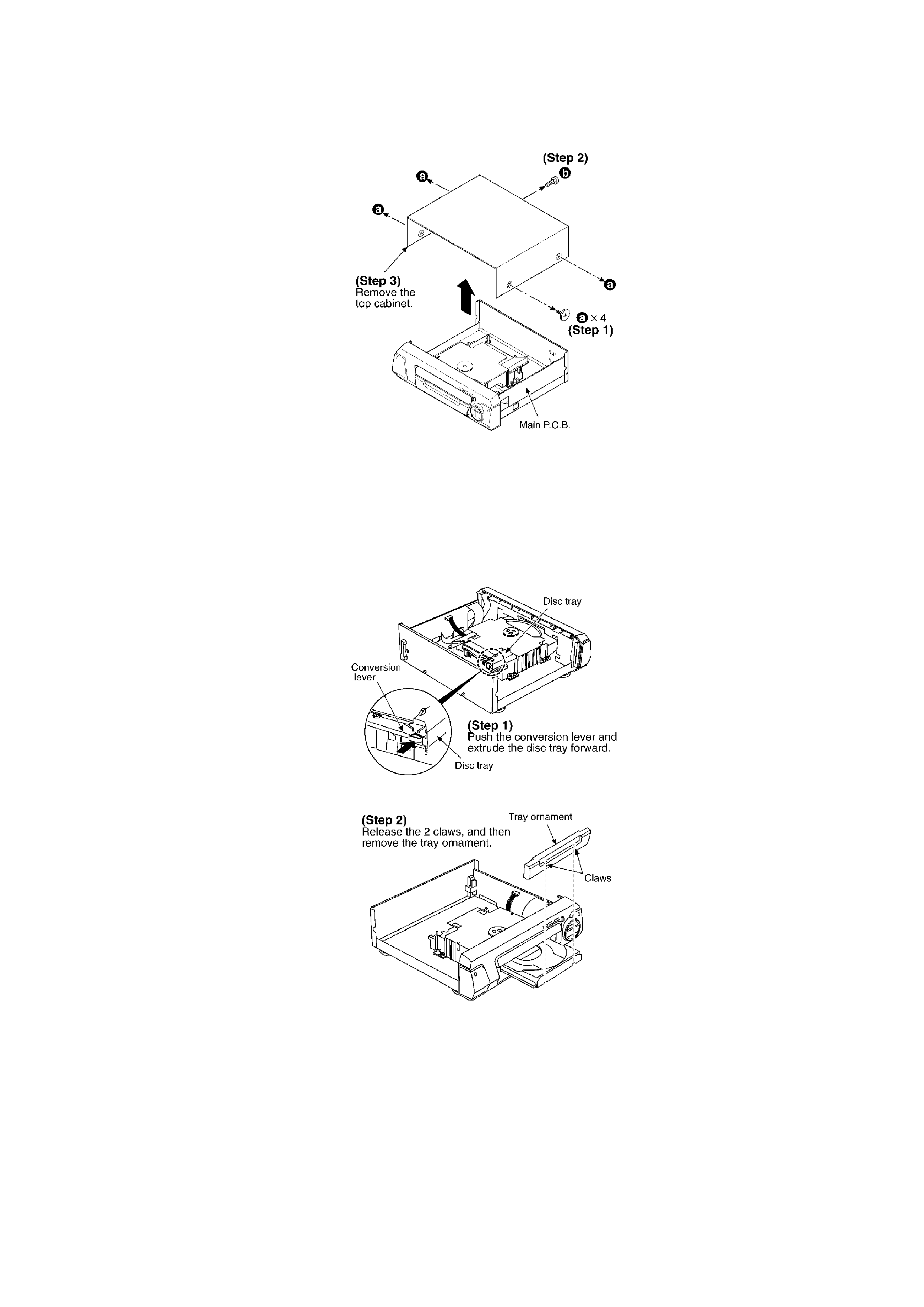
- Check the main P.C.B. as shown above.
/
5.2. Checking for the CD servo P.C.B.
- Follow the (Step 1) - (Step 3) of item 5.1.
5