ORDER NO. AD0108137C3
Turntable System
SL-1210M3D
Colour
(K)............Black Type
Area
(GN)..........Oceania.
SPECIFICATIONS
Specifications
General
Power supply:
AC 110-120/220-240V, 50 Hz
Power consumption:
16W
DImensions (W×H×D):
45.3×16.2×35.3cm
Mass:
12 kg
Turntable section
Type:
Quartz direct drive
Manual turntable
Drive method:
Direct drive
Motor:
Brushless DC motor
Turntable platter:
Aluminum diecast
Diameter 33.2cm
Mass 1.7kg
Turntable speeds:
33 1/3 r/min, 45 r/min
Starting torque:
1.5kg-cm
Build-up characteristics:
0.7s.from standstill to 33 1/3 r/
min
Braking system:
Electronic brake
Wow and flutter:
0.01% WRMS*
0.025% WRMS (JIS C5521)
±0.035%peak (IEC 98A
Weighted)
1
Rumble:
-56dB (IEC 98A Unweighted)
-78dB (IEC 98A Weighted)
*This rating refers to turntable assembly alone, excluding effects
of record, cartridge or tonearm, but including platter. Measured
by obtaining signal from built-in frequency generatorof motor
assembly.
Tonearm section
Type:
Universal
Effective length:
230mm
Arm height adjustment range:
0-6mm
Overhang:
15mm
Effective mass:
12g (without cartridge)
Offset angle:
22°
Friction:
Less than 7mg (lateral,vertical)
Tracking error angle:
Within 2°32' (at the outer
groove of 30cm record)
Within 0°32'(at the inner groove
of 30cm record)
Stylus pressure adjustment
range:
0-4g
Applicable cartridge weight
range:
3.5-13g
11-20.5g (including headshell)
(with auxiliary weight);
9.5-13g
17-20.5g (including headshell)
(with shell weight);
3.5-6.5g
11-14g (including headshell)
Headshell weight:
7.5g
Note:
Specifications are subject to change without notice.
Mass and dimensions are approximate.
2001 Matsushita Electric Industrial Co., Ltd. All rights reserved.
Unauthorized copying and distribution is a violation of law.
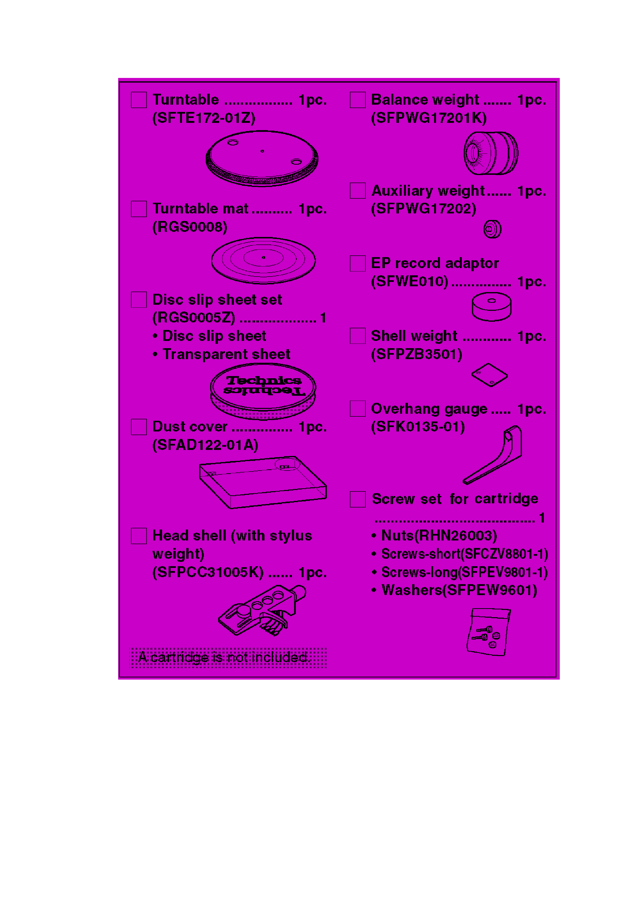
1. Accessories
2
2. Controls
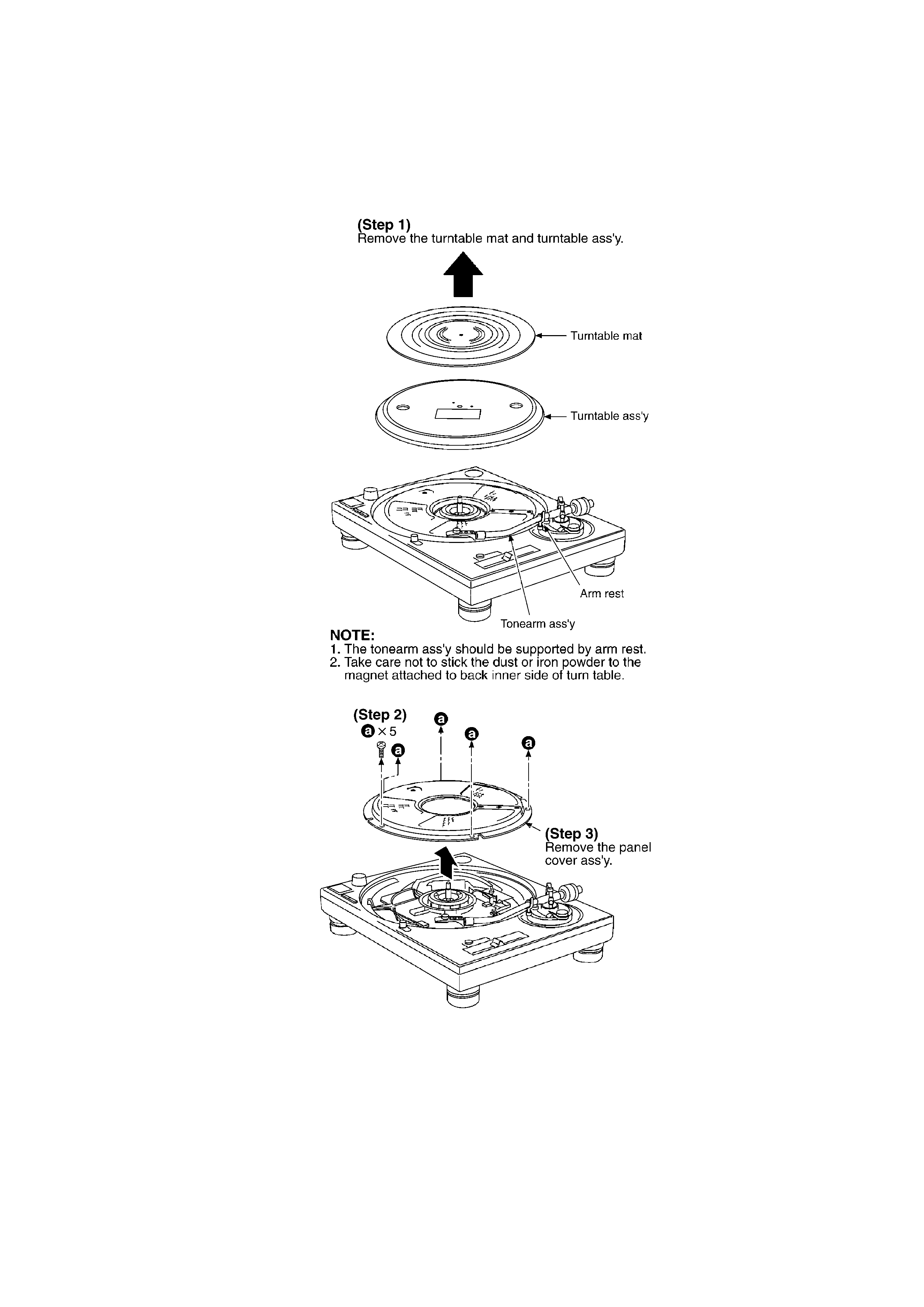
3. Operation Checks and Component Replacement
Procedures
- This section describes procedures for checking the operation of the
major printed circuit boards and replacing the main components.
- For reassembly after operation checks or replacement, reverse the
3
respective procedures. Special reassembly procedures are described
only when required.
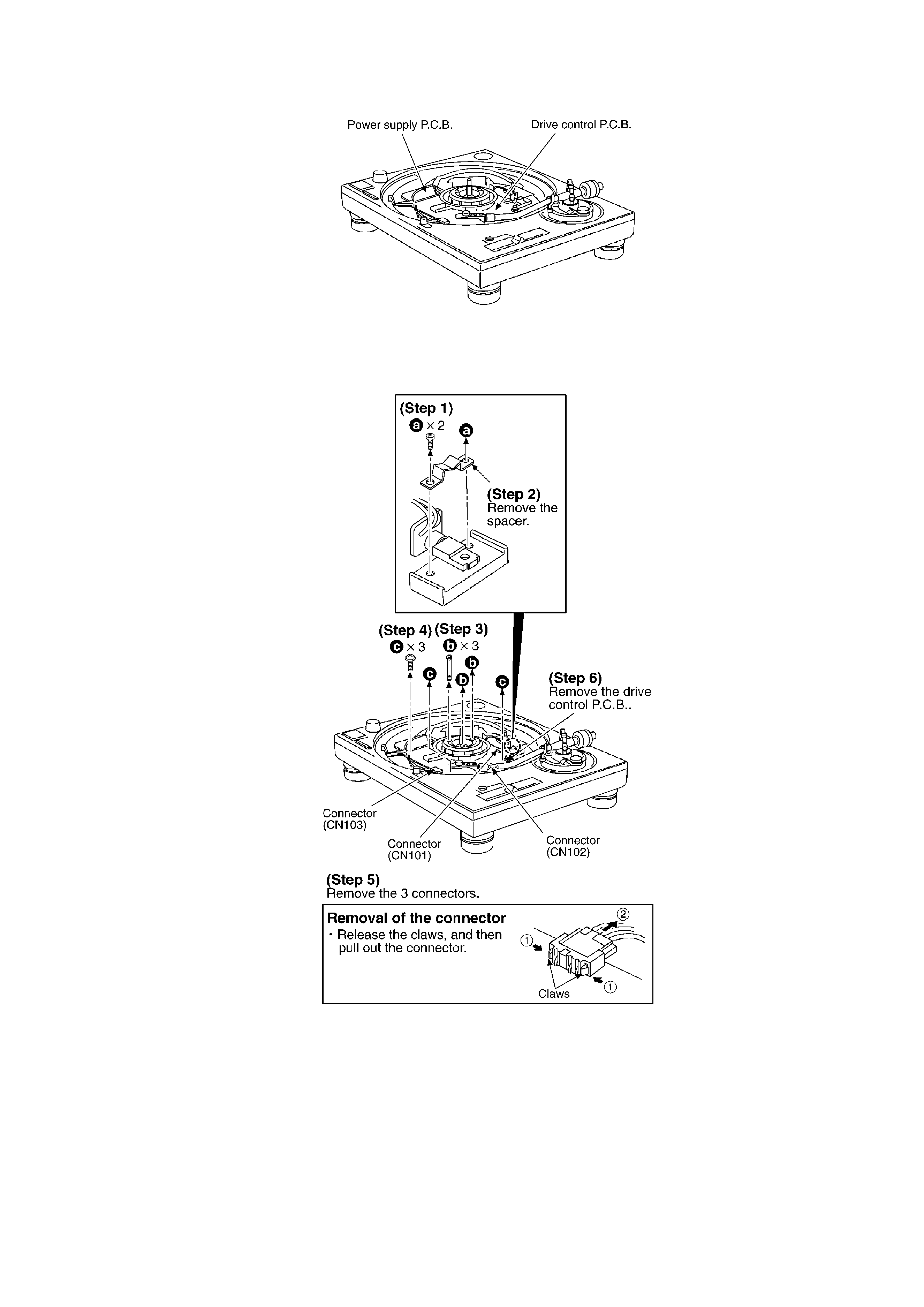
3.1. Checking for the drive control P.C.B. and power supply P.C.B.
- Check the drive control P.C.B. and power supply P.C.B. as shown
below.
4
3.2. Replacement for the drive coil ass'y and FG coil ass'y
- Follow the (Step 1) - (Step 3) of item 3.1.
5