ORDER NO.AD0303068C8
Sound Processor
SH-DV290EG
Colour
(S) ...................Silver Type
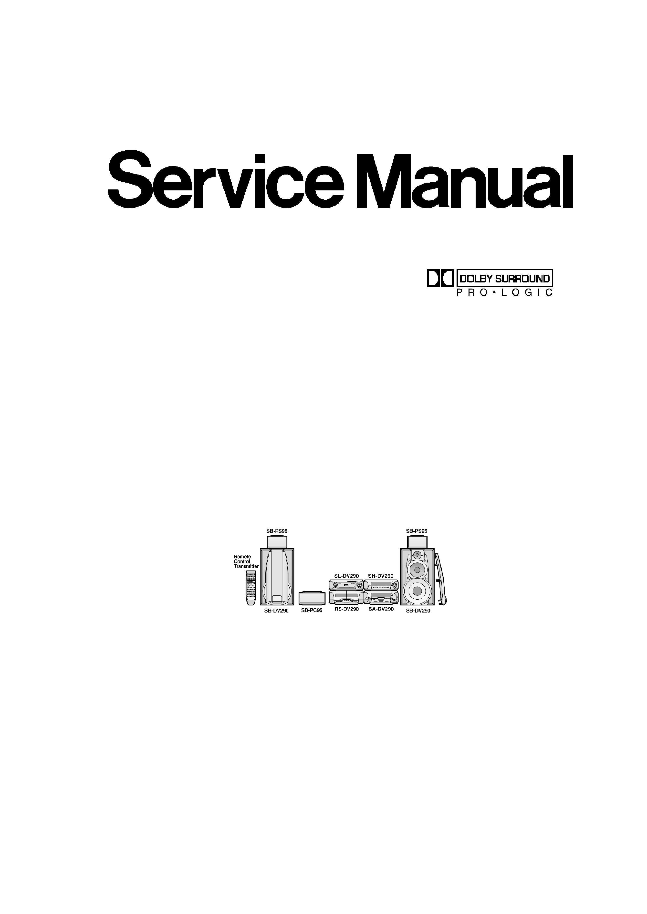
System: SC-DV290
Because of unique interconnecting cables,when a
component requires servise,send or bring in the entire
system.
Note: Refer to the service manual for Model No.
SA-DV290E/EG/EB (ORDER NO.AD0303067C2) for
information on "ACCESSORIES"and "PACKAGING".
SPECIFICATIONS
Specification
1

EQ/SFP section
MANUAL GEQ
5-Band EQ
Center frequency
70/300/1 k/3.15 k/10 kHz
Level control
±2.0, 4.0, 6.0 dB
EQ/Space mode
4 modes
HEAVY, CLEAR, SOFT, HALL
SUPER 3D AI EQ
3 modes
AI EQ, SUPER 3D AI 1, SUPER 3D AI 2
Pre-amplifier section
Input sensitivity/impedance
VCR (EXT)
250 mV/15 k
VDP (AUX)
250 mV/15 k
Output level
VCR REC OUT
150 mV/1.5 k
DOLBY PRO LOGIC section
PRO LOGIC mode
SURROUND
CENTER mode
NORMAL
DELAY TIME
20 ms (Fixed)
AV SURROUND section
AV surround mode
SUPER SURROUND (MUSIC, MOVIE)
DSP CONTROL section
DSP control mode
SUPER SOUND EQ
CENTER FOCUS
VIRTUAL REAR SURROUND
MULTI REAR SURROUND
SEAT POSITION
Spectrum analyzer section
Display mode
NORMAL, PEAKHOLD, AURORA
General
Dimensions (W×H×D)
293×89×270 mm
Mass
1.5 kg
Power Supply
DC±10V/ -25V, AC4.6V
Power Consumption
7W
Nots
1.Design and specifications are subject to
change without notice.
2.Dimensions and weight are approximate.
3.Total harmonic distortion is measured by the
digital spectrum analyzer.
System/SC-DV290
Sound processor: SH-DV290, DVD/ Video CD/ CD
changer: SL-DV290, Tuner/ Amplifier: SA-DV290 ,
Cassette Deck: RS-DV290, Speakers: Front* (SB-
DV290),Center* (SB-PC95),Surround* (SB-PS95)
(*Made in MAES.)
Manufactured under license from Dolby Laboratories. /
"Dolby","Pro Logic" and the double-D symbol are
trademarks of Dolby Laboratories.
2
1. Before Repair
This equipment (SH-DV290), which is the component of the system, is supplied with power from
the amplifier (SA-DV290).When repairing this equipment or checking operation of the system, be
sure to connect the amplifier with it.
Power supply and operation check in the state of it as a single equipmenet are impracticable.
2. Operating Instructions
3. Operation Checks and Component Replacement
Procedures
- This section describes procedures for checking the operation of
the major printed circuit boards and replacing the main
components.
- For reassembly after operation checks or replacement, reverse the
respective procedures. Special reassembly procedures are
described only when required.
3.1. Checking for the FL P.C.B.
3
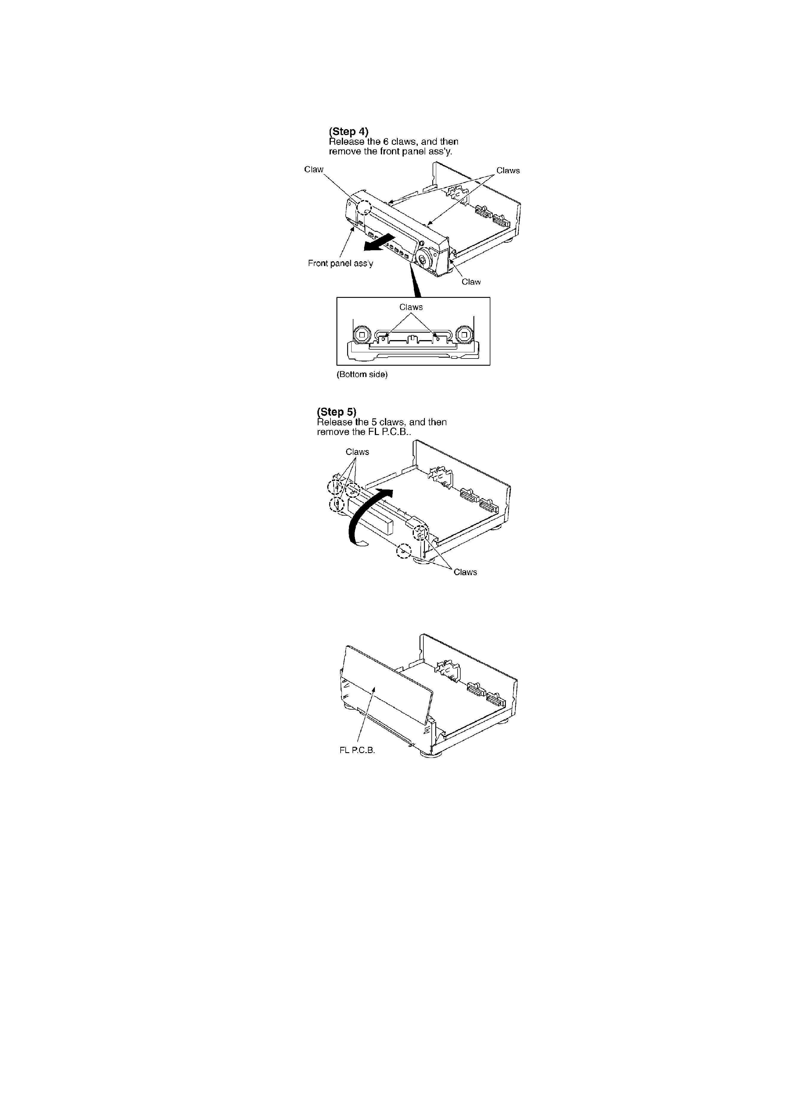
- Check the FL P.C.B. as shown below.
3.2. Checking for the main P.C.B.
- Follow the (Step 1) - (Step 3) of item 3.1.
4
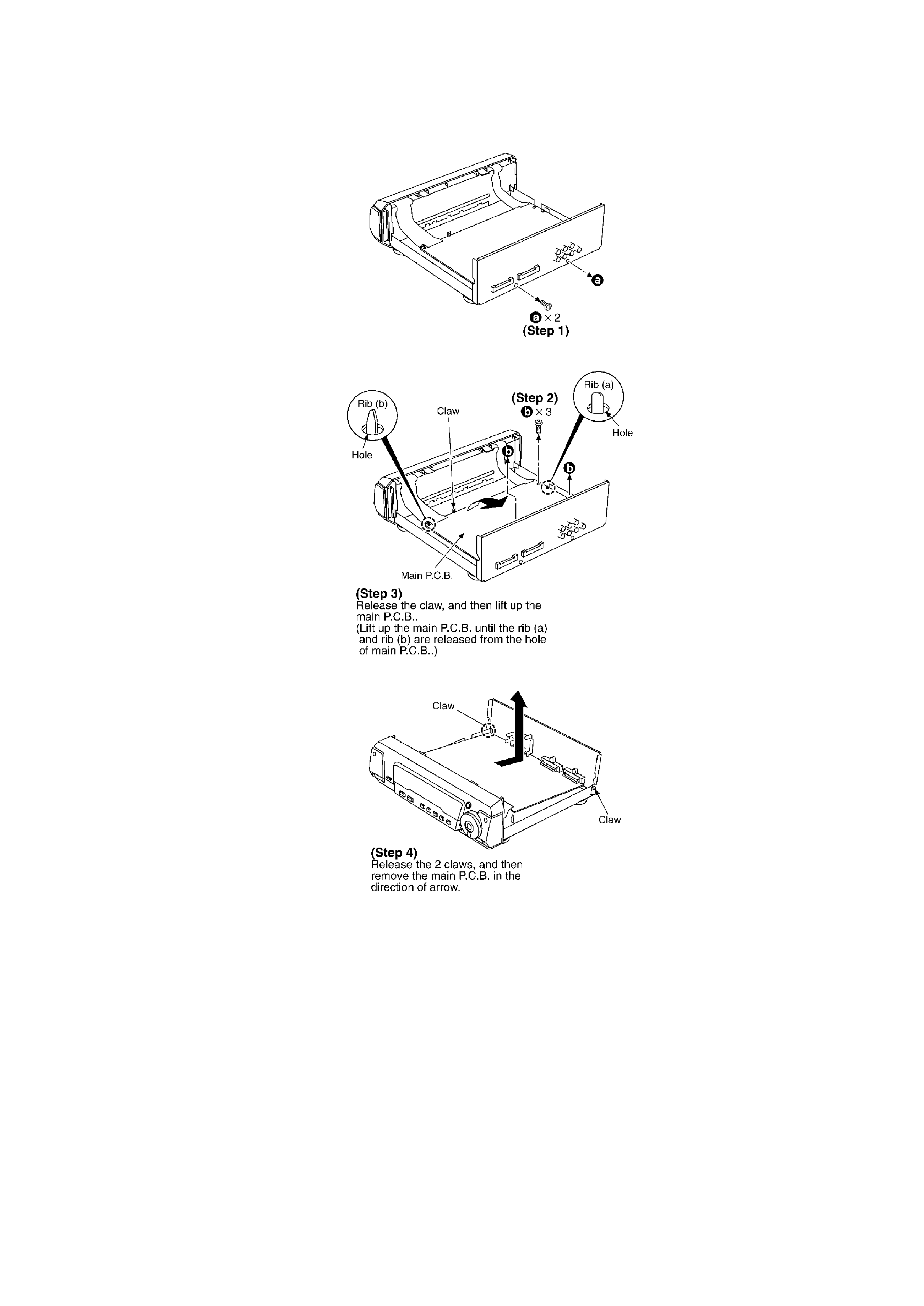
- Check the main P.C.B. as shown below.
5