
ORDER NO. MEP0002250C1
A2
Speaker System
SB-AS100
Color
(K)...............Black Type
Area
P.................U.S.A.
1
SPECIFICATIONS
Specifications
2
SPEAKER SECTION
Type
1 way 2 speaker system
Bass-reflex type
Speaker
Woofer
14 cm (5-1/2") cone type × 2
Impedance
1
Input power
Music
200 W
DIN
100 W
Sound pressure level
82 dB/W (1.0 m)
Frequency response
40-380 Hz (-16 dB)
45-310 Hz (-10 dB)
AMPLIFIER SECTION
Continuous power putput
20-200 Hz (THD 1%)
100 W (1
)
Phase switching
NORMAL/REVERSE
Input sensitivity/Impedance
335 mV/15 k
Low pass filter
50-200Hz variable
GENERAL
Power supply
AC 120 V, 60Hz
Power consumption
40 W
Dimensions (W×H×D)
231×450×350 mm
(9-3/32"×17-23/32"×13-25/32")
Weight
9 kg (19.8 lb.)
Notes:
Specifications are subject to change without notice.
Weight and dimensions are approximate.
2000 Matsushita Electric Industrial Co., Ltd. All rights reserved.
Unauthorized copying and distribution is a violation of law.
1. Safety Precaution
1. Before servicing, unplug the power cord to prevent an electric
shock.
3
2. When replacing parts, use only manufacturer's recommended
components for safety.
3. Check the condition of the power cord. Replace if wear or
damage is evident.
4. After servicing, be sure to restore the lead dress, insulation
barriers, insulation papers, shields, etc.
5. Before returning the serviced equipment to the customer, be sure
to make the following insulation resistance test to prevent the
customer from being exposed to a shock hazard.
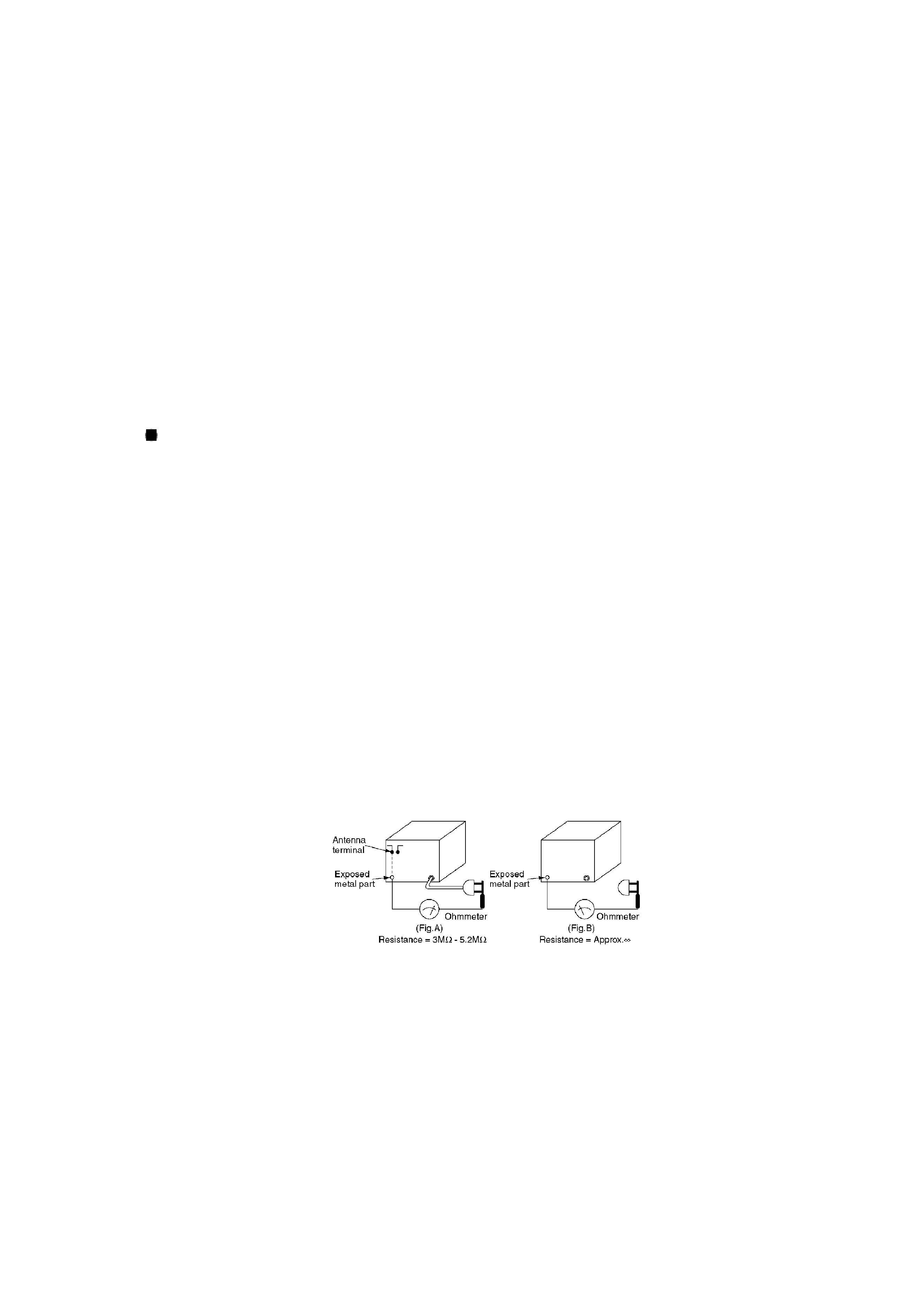
INSULATION RESISTANCE TEST
1. Unplug the power cord and short the two pongs of the with a
jumper wire.
2. Turn on the power switch.
3. Measure the resistance value with ohmmeter between the
jumpered AC plug and each exposed metal cabinet part, such as
screwheads, control shafts, handle brackets, etc. Equipment with
antenna terminals should read between 3MW and 5.2MW to all
exposed parts.(Fig. A) Equipment without antenna terminal
should read approximately infinity to all exposed parts.(Fig. B)
Note:
Some exposed parts may be isolated from the chassis by design. These will read infinity.
4. If the measurement is outside the specified limits, there is
possibility of a shock hazard. The equipment should be repaired
and rechecked before it is returned to the customer.
2. Identifying the Suffix of Each Set
Identify the suffix of each set using the serial number located on the back side of a set.
4
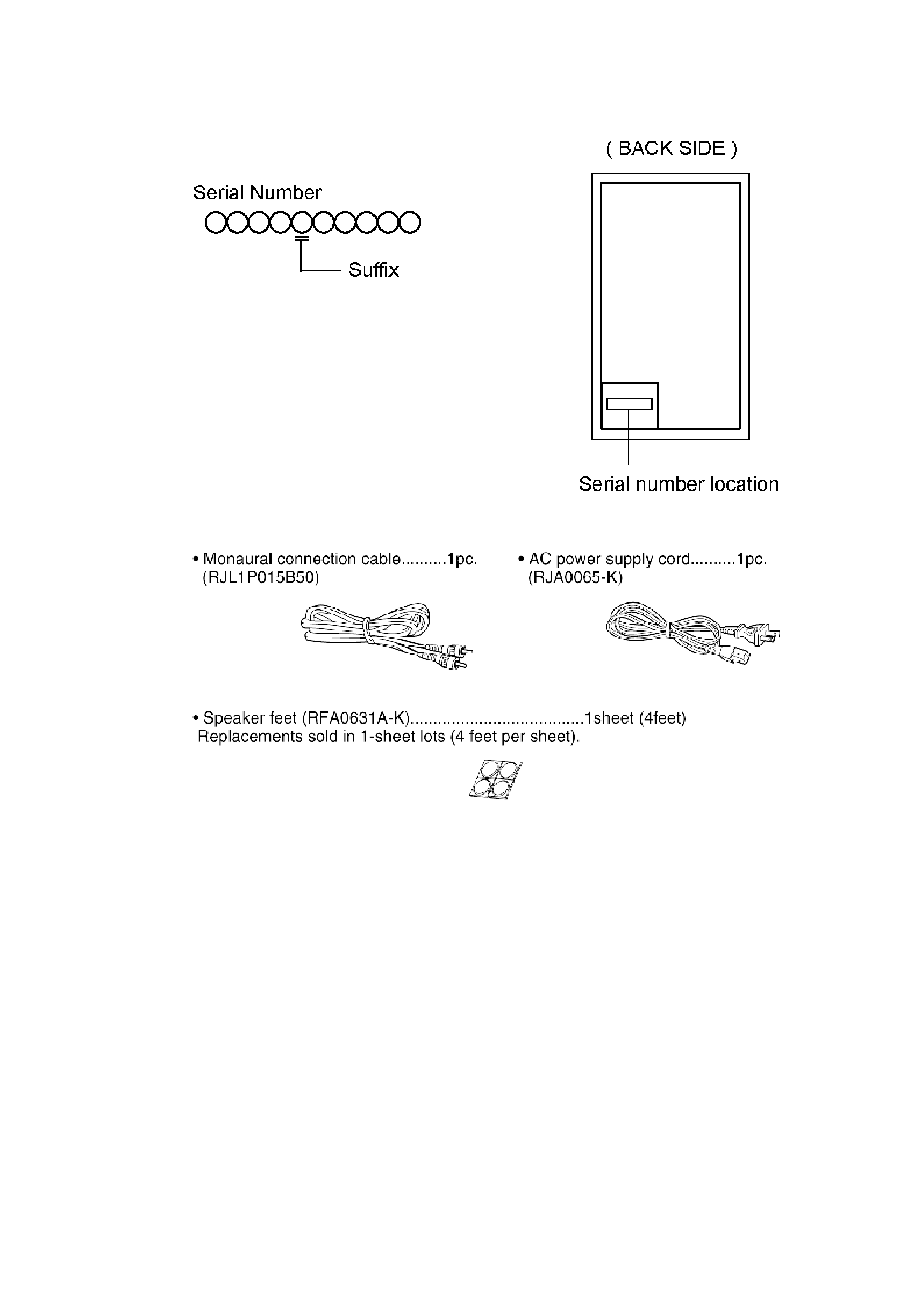
3. Accessories
4. Operation Checks and Component Replacement
Procedures
- This section describes procedures for checking the operation of
the major printed circuit boards and replacing the main
components.
- For reassembly after operation checks or replacement, reverse the
respective procedures. Special reassembly procedures are
described only when required.
/
4.1. Checking for the control P.C.B., power P.C.B. and main P.C.B.
5