Order No. MD0003027C1
A2
AV Control Stereo Receiver
SA-EX140
Color
(K) ... Black Type
P ... U.S.A.
PC ... Canada
SPECIFICATIONS
FM Tuner Section
Frequency Range
87.9-107.9 MHz
Sensitivity
11.2 dBf (2
V, IHF'58)
50 dB quieting sensitivity
MONO
18.3 dBf (4.5
V, IHF'58)
STEREO
38.3 dBf (45
V, IHF'58)
Total harmonic distortion
MONO
0.2%
STEREO
0.3%
S/N
MONO
75 dB
STEREO
70 dB
Frequency response
20 Hz-15 kHz, +1 dB, -2 dB
Alternate channel selectivity
65 dB
Capture ratio
1 dB
Image rejection at 98 MHz
44 dB
IF rejection at 98 MHz
80 dB
Spurious response rejection at 98
MHz
75 dB
AM suppression
50 dB
Stereo separation
1 kHz
40 dB
10 kHz
30 dB
1

Carrier leak
19 kHz
-35 dB
38 kHz
-50 dB
Antenna terminal
75
(unbalanced)
AM Tuner Section
Frequency Range
530-1710 kHz
Sensitivity
20
V, 330
V/m
Selectivity
55 dB
Image rejection at 1000 kHz
40 dB
IF rejection at 1000 kHz
60 dB
Amplifier Section
Rated minimum sine wave RMS
power output
40 Hz-20 kHz both channel driven
0.8% total harmonic distortion
100W per channel (8
)
1 kHz continuous power output both
channels driven
0.8% total harmonic distortion
103W per channel (8
)
Total harmonic distortion
rated power at 40 Hz-20 kHz
0.8% (8
)
half power at 1 kHz
0.07% (8
)
Low frequency damping factor
30 (8
)
Load impedance
A or B
8
Dynamic headroom
2 dB (8
)
SMPTE intermodulation distortion
0.3%
Frequency response
PHONO
RIAA standard curve ±0.8
dB
CD, TAPE, VCR
10 Hz-70 kHz, ±3 dB
Input sensitivity
PHONO
0.4 mV (3 mV, IHF'66)
CD, TAPE, VCR
27mV (200 mV, IHF'66)
S/N (IHF A)
PHONO
70 dB (78 dB, IHF'66)
CD, TAPE, VCR
75 dB (83 dB, IHF'66)
Input impedance
PHONO
47 k
CD, TAPE, VCR
22 k
Tone controls
BASS
50 Hz, +10 to -10 dB
TREBLE
20 kHz, +10 to -10 dB
General
Power consumption
155 W
Power supply
AC 120 V, 60 Hz
Dimensions (WxHxD)
430 x 136 x 312 mm
(16-15/16" x 5-11/32" x 12-9/32")
Weight
6.4 kg (14.1 lb.)
2
Notes:
1. Specifications are subject to change without notice. / Weights and
dimensions are approximate.
2. Total harmonic distortion is measured by the digital spectrum analyzer.
2000 Matsushita Electronics (S) Pte. Ltd. All rights reserved.
Unauthorized copying and distribution is a violation of law.
1. Safety Precaution
(This "Safety Precaution" is applied only in U.S.A.)
1. Before servicing, unplug the power cord to prevent an electric
shock.
2. When replacing parts, use only manufacturer's recommended
components for safety.
3. Check the condition of the power cord. Replace if wear or
damage is evident.
4. After servicing, be sure to restore the lead dress, insulation
barriers, insulation papers, shields, etc.
5. Before returning the serviced equipment to the customer, be sure
to make the following insulation resistance test to prevent the
customer from being exposed to a shock hazard.
- Insulation Resistance Test
1. Unplug the power cord and short the two prongs of the plug with
a jumper wire.
2. Turn on the power switch.
3. Measure the resistance value with ohmmeter between the jumper
AC plug and each exposed metal cabinet part, such as screw
heads, antenna, control shafts, handle brackets, etc. Equipment
with antenna terminals should read between 3M
and 5.2M
to
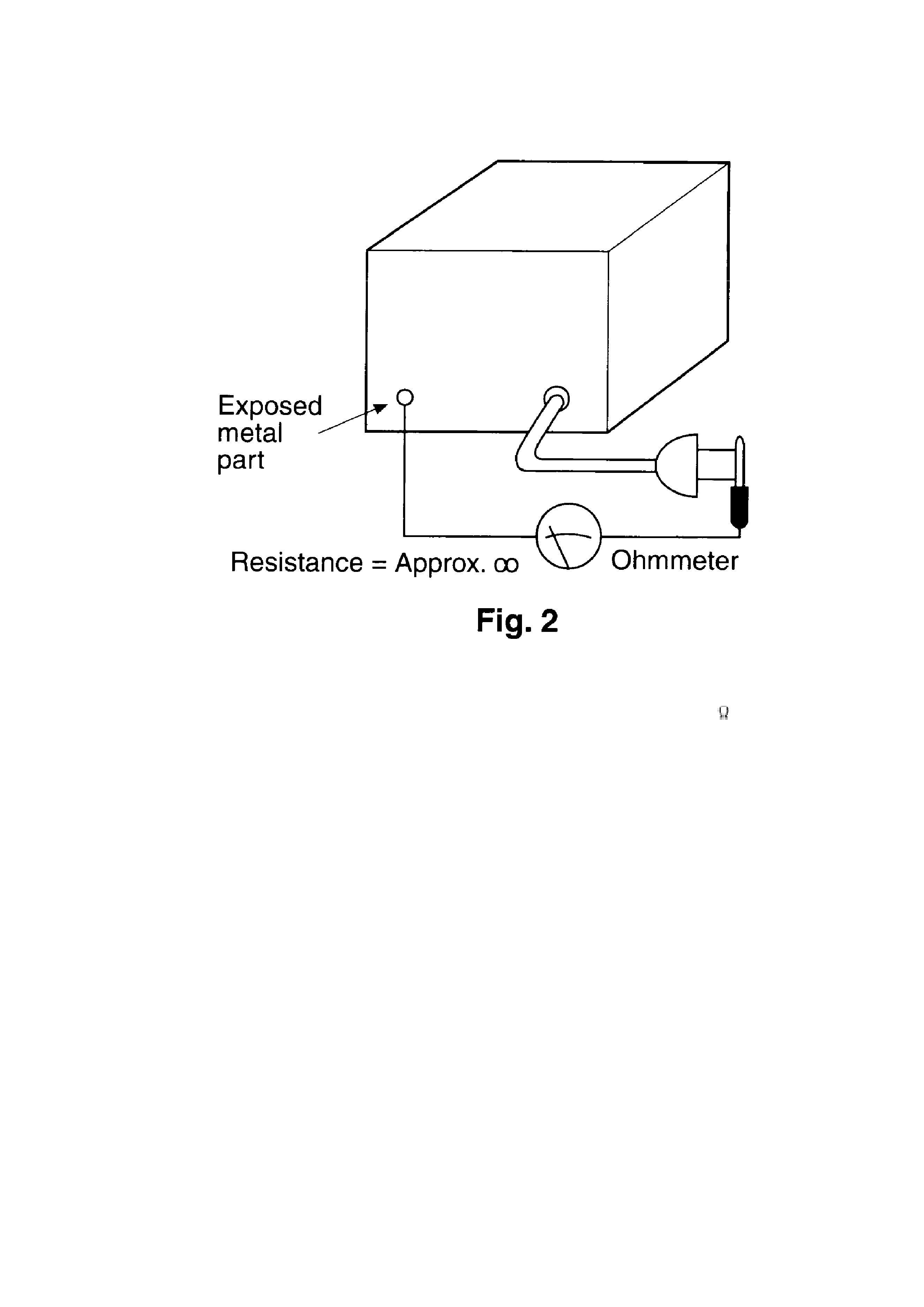
all exposed parts*. (Fig 1) Equipment without antenna terminals
3
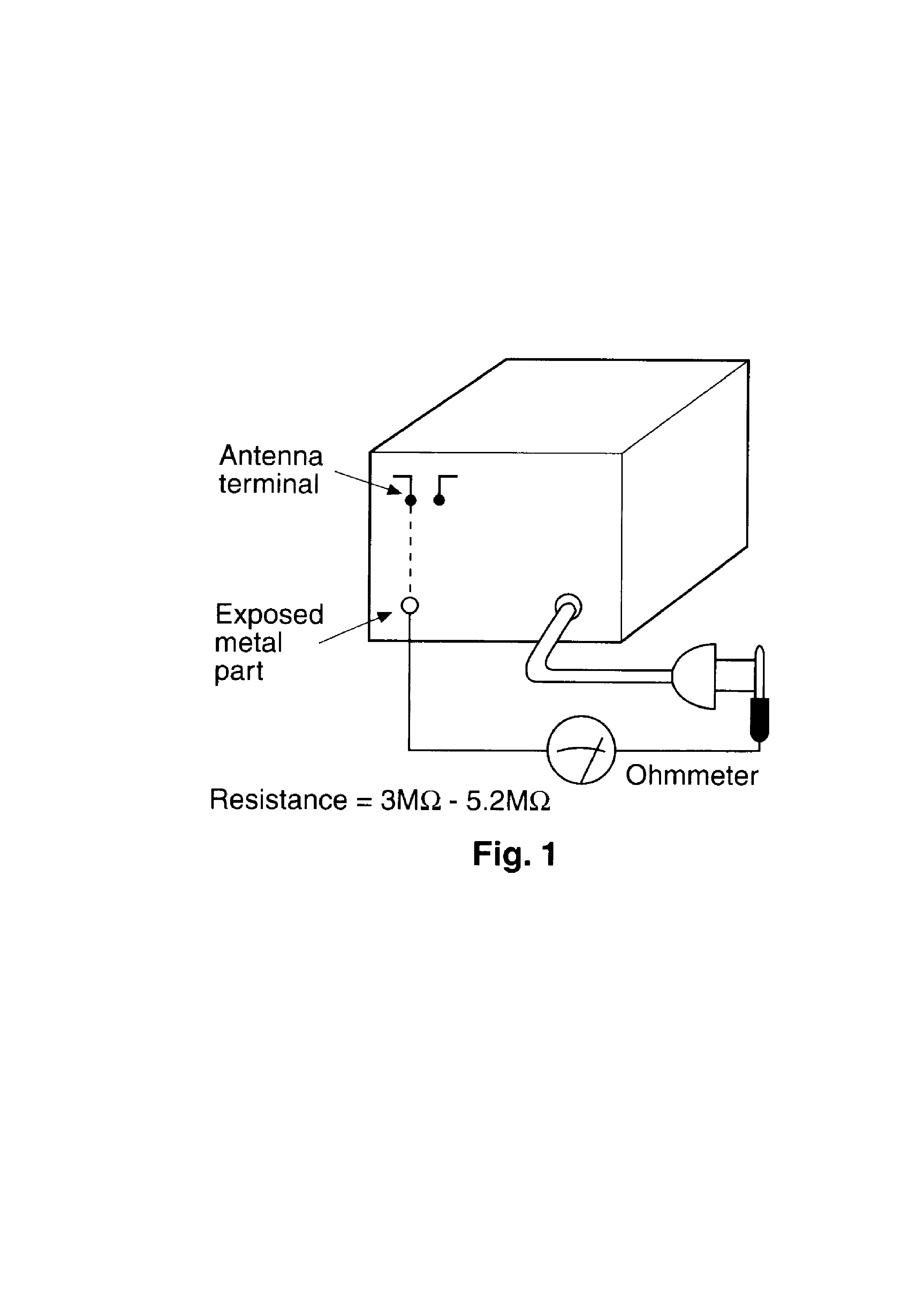
should read approximately infinity to all exposed parts. (Fig 2)
*Note: Some exposed parts may be isolated from the chassis by
design. These will read infinity.
4. If the measurement is outside the specified limits, there is a
possibility of a shock hazard. The equipment should be repaired
and rechecked before it is returned to the customer.
4
2. Before Repair and Adjustment
Disconnect AC power, discharge Power Supply Capacitors C753 through a 10
, 5 W resistor
to ground. DO NOT SHORT-CIRCUIT DIRECTLY (with a screw driver blade, for instance), as this
may destroy solid state devices.
After repairs are completed, restore power gradually using a variac, to avoid over current.
Current consumption at AC 120 V, 60 Hz in NO SIGNAL mode should be 300~800 mA.
3. Protection Circuitry
The protection circuitry may have operated if either of the following conditions are noticed:
- No sound is heard when the power is turned on.
- Stops during a performance.
The function of this circuitry is to prevent circuitry damage if, for example, the positive and
negative speaker connection wires are "shorted", or if speaker systems with an impedance less
than the indicated rated impedance of the amplifier are used.
If this occurs, follow the procedure outlines below:
1. Turn off the power.
2. Determine the cause of the problem and correct it.
3. Turn on the power once again after one minute.
Note:
When the protection circuitry functions, the unit will not operate unless the power is first turned
5