- 2 -
3
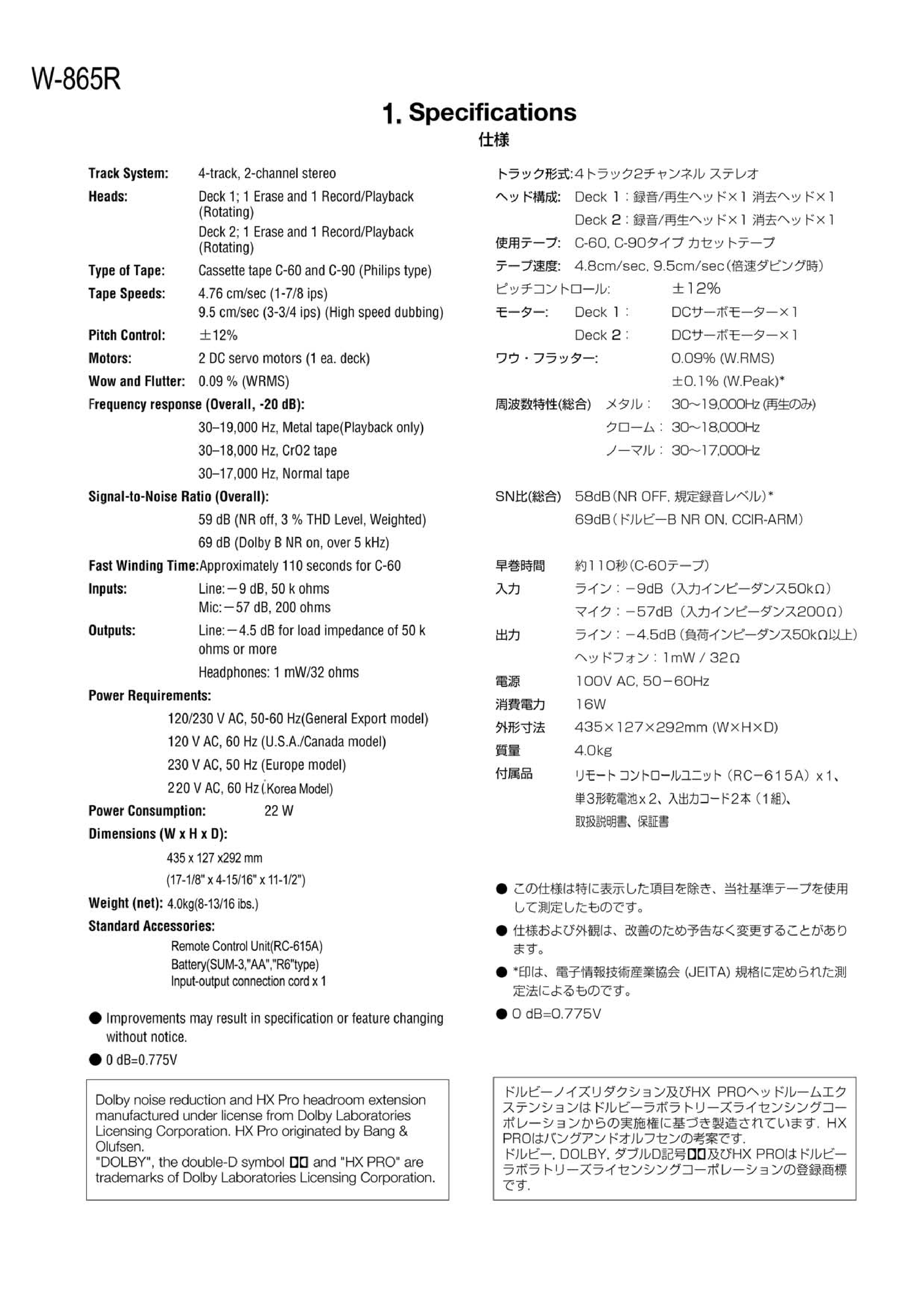
2 Adjustment and Checks
TASCAM 202MK
2-1 MECHANICAL ADJUSTMENT
2-1-1 Wow and flutter (playback method)
In both FWD and REV play modes, these measurements should
be made at the beginning, middle, and the end of the tape.
1. Connect a wow-and-flutter meter to the LINE OUT.
2. Load and play a TEAC MTT-111N test tape.
3. Check that the readings on the wow-and-flutter meter is within
0.19% (JIS WTD).
2-1-2 Tape speed
1. Connect a frequency counter to the LINE OUT.
2. Load a TEAC MTT-111N test tape and play in FWD direction
the beginning of the test tape.
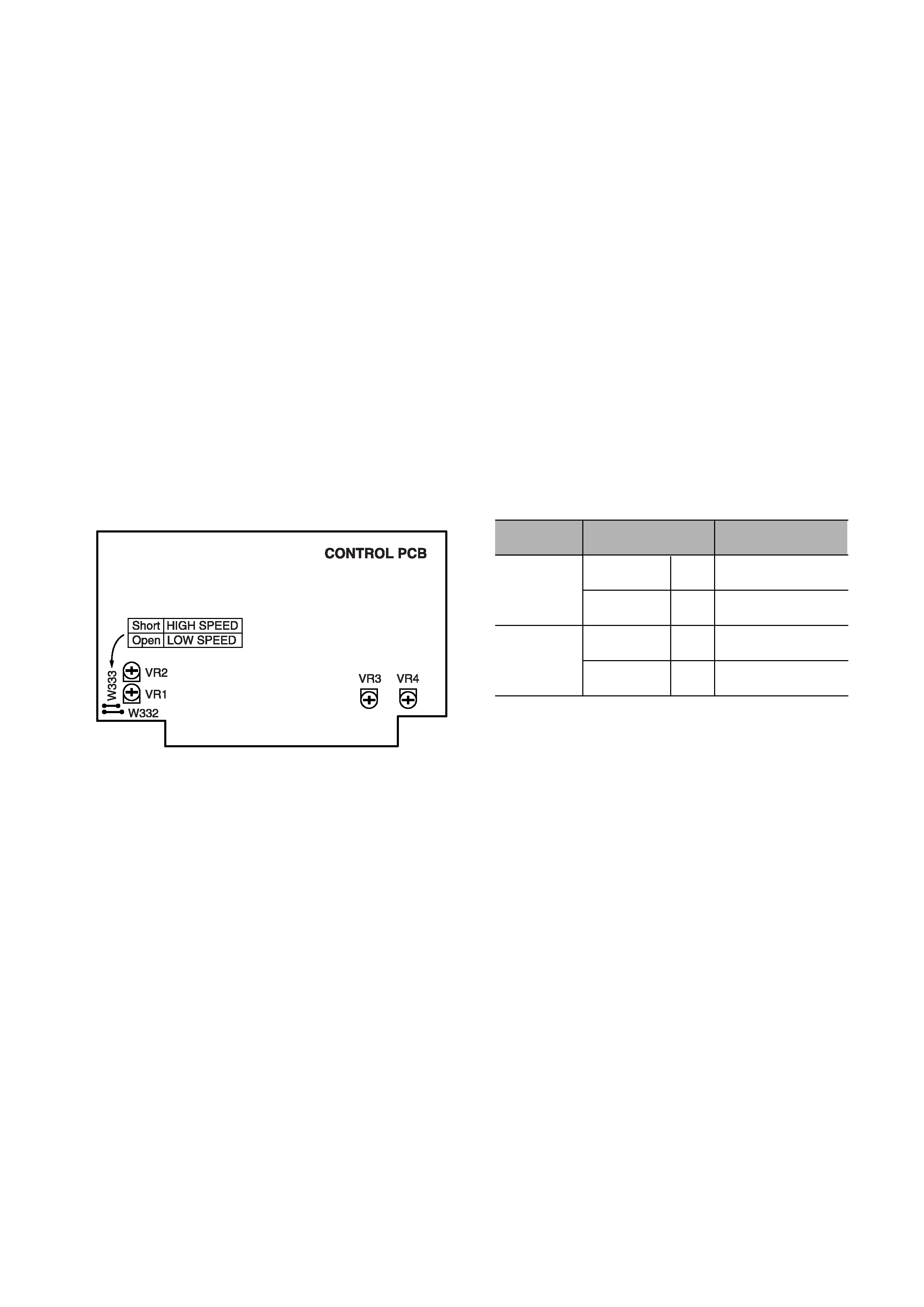
3. Adjust each variable resistor to get the following values.
4. In play mode, check that the following values are obtained at
the beginning and end of the tape.
Speed drifting
Within 120Hz (HIGH speed)
Within 60Hz (LOW speed)
2-1-3 Reel torque
1. Load the cassette torque meter on the deck and read the
pointer indication on the dial scale for each tape transport
operation. The measured torque should be within the following
specified values.
Take-up:
30 to 70g-cm
Supply:
1.5 to 6g-cm
FF/REW:
70 to 150g-cm
Torque meter
MTT-8111W:
Forward torque & back tension
MTT-8121W:
Reverse torque & back tension
MTT-8242:
Fast forward & rewind static torque
Fig. 2-1
REC/PLAY
1
REC/PLAY
2
Adjustment point
Adjustment value
HIGH speed
6,000 30Hz
LOW speed
3,000 20Hz
HIGH speed
6,000 30Hz
LOW speed
VR2
VR1
VR4
VR3
3,000 20Hz
W-865R
4
2-2 ELECTRICAL ADJUSTMENT
2-2-1 Precautions
Before performing adjustments and checks clean and demag
netize the entire tape path.
In general, adjustments and checks are made in the order of
Lch then Rch. Double REF. Nos. indicate Lch/Rch. (Example;
R11/R21)
0dB is referenced to 0.775V.
The AC voltmeter used in the procedures must have an input
impedance of 1M
or more.
Unless specified otherwise, adjustments and checks are made
in FWD direction.
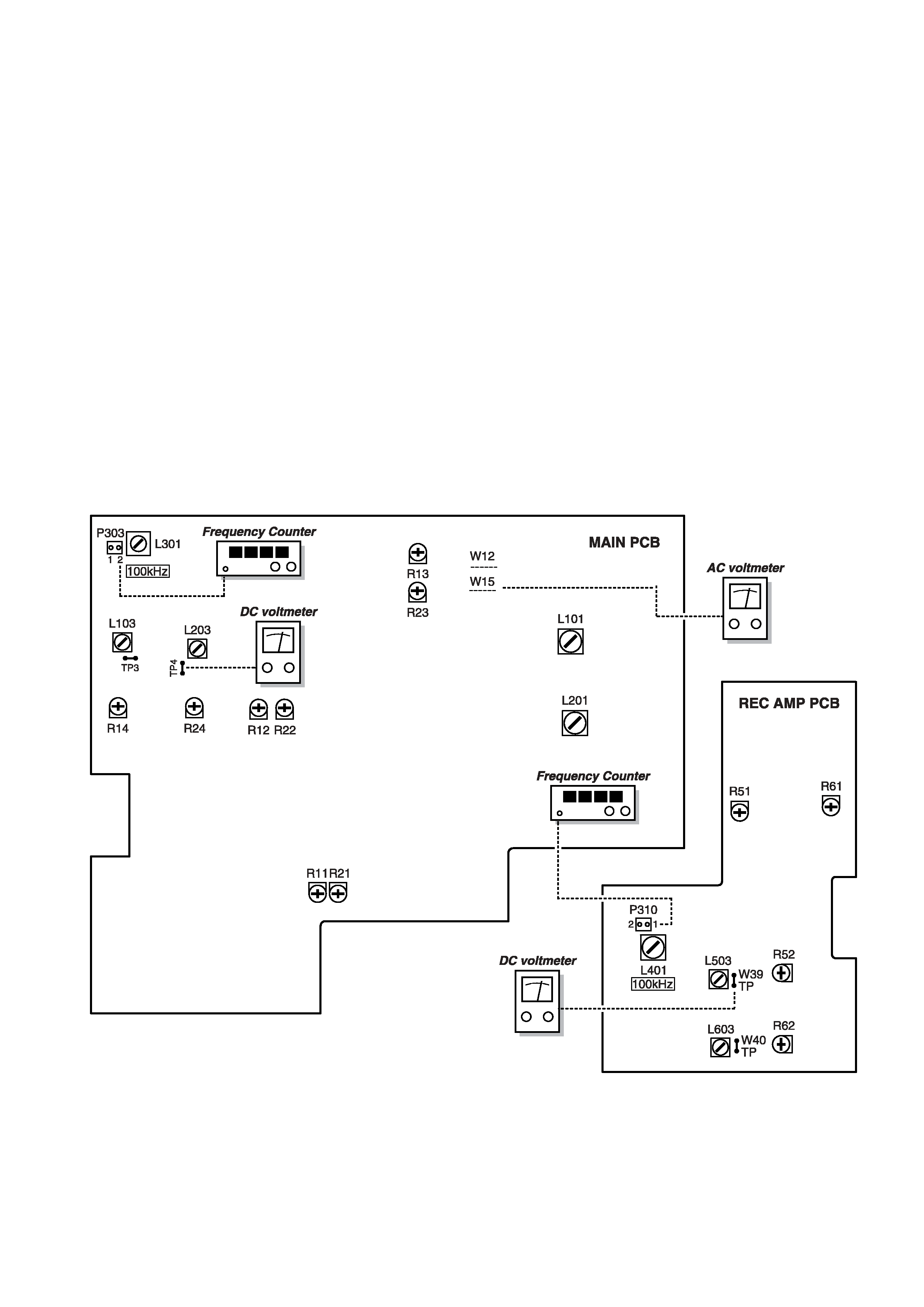
2-2-2 Adjustment locations
Fig. 2-2
W-865R
5
2-2-3 Playback performance
Deck settings:
TEAC test tapes:
Mode: PLAY
MTT-150: For Dolby level calibration
DOLBY NR Switch: OFF
MTT-25702: For playback frequency response check NORMAL tape
MTT-5513: For S/N check NORMAL tape
ITEM
SETTING
INPUT SIGNAL
ADJUSTMENTS
MEASURING
POINTS, RESULT
REMARKS
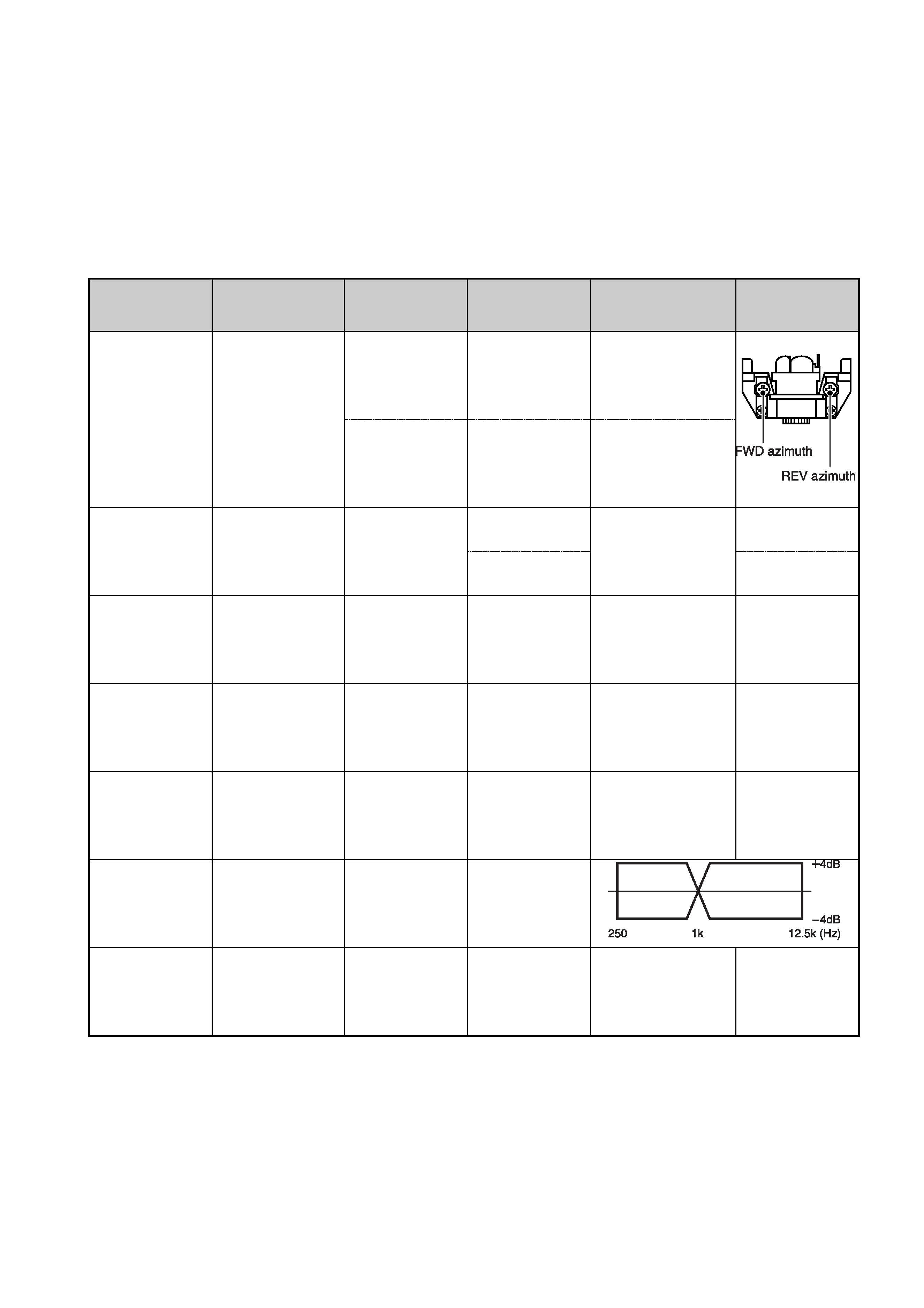
1. Head
azimuth
adjustment
Connection:Fig. 2-4
Check and adjust in
FWD, REV respec-
tively
FWD
REV
MTT-150C
LINE OUT:
Phase: within 45
: 45
(Fig. 2-5)
2. DOLBY level
Connection:Fig. 2-2
FWD PLAY
MTT-150C
R11/R21
W12/W15:
300mV
REC/PLAY
3. Playback
output level
Connection:Fig. 2-3
FWD/REV PLAY
MTT-150C
Check
LINE OUT:
4.5
1dB
Ref. output level
4. Meter level
MTT-150C
Check
LEVEL METER:
mark 1dot
5. PHONES
output level
MTT-150C
Check
PHONES:
13
3dB
32
load
32
6. Playback
frequency
response
Connection:Fig. 2-3
MTT-25702
Check
7. Playback
S/N ratio
Connection:Fig. 2-3
MTT-5513
Playback the
leader tape portion
Check
46dB min.
Ratio of ref.
level to noise
MTT-25702
(12.5kHz)
Azimuth screws
LINE OUT:
Maximum output
level at L & R-ch
Lch
Rch
R12/R22
REC/PLAY
W-865R