W
W--8
86
60
0R
R
SERVICE MANUAL
Double Cassette Deck
Effective : April, 1999
D00484800A
NOTES
PC boards shown are viewed from parts side.
Parts marked with * require longer delivery time.
The parts with no reference number or no parts number in the
exploded views are not supplied.
As regards the resistors and capacitors, refer to the circuit diagrams
contained in this manual.
£
Parts marked with this sign are safety critical components. They
must be replaced with identical components - refer to the appropriate
parts list and ensure exact replacement.
Parts of [ ] mark can be used only with the version designated.
£
CONTENTS
1 SPECIFICATIONS
2
2 ADJUSTMENT AND CHECKS
3
3 EXPLODED VIEWS AND PARTS LIST
8
4 PC BOARDS AND PARTS LIST
12

W-860R
2
1 SPECIFICATIONS
Track System:
4-track, 2-channel stereo
Heads:
Deck ; 1 Erase and 1 Record/Playback
(Rotating)
Deck ; 1 Erase and 1 Record/Playback
(Rotating)
Type of Tape:
Cassette tape C-60 and C-90 (Philips
type)
Tape Speeds:
4.76 cm/sec (1-7/8 ips)
9.5 cm/sec (3-3/4 ips) (High speed
dubbing)
Pitch Control:
10%
Motors:
2 DC servo motors (1 ea. deck)
Wow and Flutter:
0.09 % (WRMS)
Frequency response (Overall, -20 dB):
2519,000 Hz, Metal tape
2518,000 Hz, CrO2 tape
2517,000 Hz, Normal tape
Signal-to-Noise Ratio (Overall):
59 dB (NR off, 3 % THD Level,
Weighted)
69 dB (Dolby B NR on, over 5 kHz)
79 dB (Dolby C NR on, over 1 kHz)
Fast Winding Time: Approximately 110 seconds for C-60
Inputs:
Line: 97 mV, 50 k ohms
Mic: 0.38 mV, 200 ohms
Outputs:
Line: 0.52 V for load impedance of 50 k
ohms or more
Headphones: 1 mW/8 ohms
Power Requirements: 120/230 V AC, 50-60 Hz
(General Export model)
120 V AC, 60 Hz
(U.S.A./Canada model)
230 V AC, 50 Hz (Europe model)
240 V AC, 50 Hz (Australia model)
Power Consumption: 22 W
Dimensions (W x H x D):
435 x 127 x 292 mm
(17-1/8" x 4-15/16" x 11-1/2")
Weight (net):
4.0 kg (8-13/16 lbs.)
Standard Accessories:
Remote control unit (RC-615) x 1
(General Export/Europe/UK/Australia
model), Battery (SUM-3, "AA", "R6"
type) x 2 (General Export/Europe/UK/
Australia model), Input-output
connection cord x 1
Improvements may result in specification or feature changing
without notice.
Dolby noise reduction and HX Pro headroom extension
manufactured under license from Dolby Laboratories
Licensing Corporation. HX Pro originated by Bang &
Olufsen.
"DOLBY", the double-D symbol
and "HX PRO" are
trademarks of Dolby Laboratories Licensing Corporation.
W-860R
3
2 ADJUSTMENTS AND CHECKS
2-1 MECHANICAL ADJUSTMENT
2-1-1 Wow and flutter (playback method)
In both FWD and REV play modes, these measurements should
be made at the beginning, middle, and the end of the tape.
1. Connect a wow-and-flutter meter to the LINE OUT.
2. Load and play a TEAC MTT-111N test tape.
3. Check that the readings on the wow-and-flutter meter is
within 0.19% (JIS WTD).
2-1-2 Tape speed
1. Connect a frequency counter to the LINE OUT.
2. Load a TEAC MTT-111N test tape and play in FWD
direction the beginning of the test tape.
3. Adjust each variable resistor to get the following values.
4. In play mode, check that the following values are obtained at
the beginning and end of the tape.
Speed drifting: Within 120Hz (HIGH speed)
Within 60Hz (LOW speed)
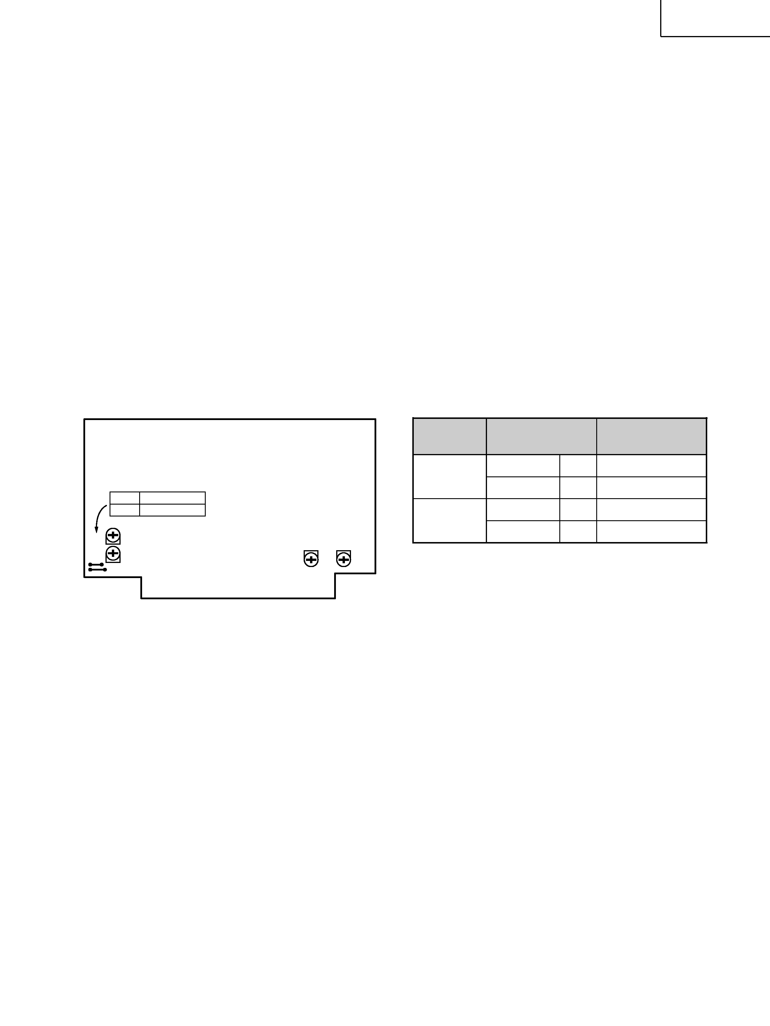
2-1-3 Reel torque
1. Load the cassette torque meter on the deck and read the
pointer indication on the dial scale for each tape transport
operation. The measured torque should be within the
following specified values.
Take-up: 30 to 70g cm
Supply: 1.5 to 6g-cm
FF/REW: 70 to 150g-cm
Torque meter
MTT-8111W: Forward torque & back tension
MTT-8121W: Reverse torque & back tension
MTT-8242: Fast forward & rewind static torque
Adjustment point
Adjustment value
REC/PLAY
REC/PLAY
Fig. 2-1
VR3
VR4
VR2
VR1
W332
W333
Short HIGH SPEED
Open LOW SPEED
CONTROL PCB
2-2 ELECTRICAL ADJUSTMENT
2-2-1 Precautions
Before performing adjustments and checks clean and
demagnetize the entire tape path.
In general, adjustments and checks are made in the order of
Lch then Rch. Double REF. Nos. indicate Lch/Rch.
(Example; R11/R21)
0dB is referenced to 0.775V.
The AC voltmeter used in the procedures must have an input
impedance of 1M
or more.
Unless specified otherwise, adjustments and checks are made
in FWD direction.
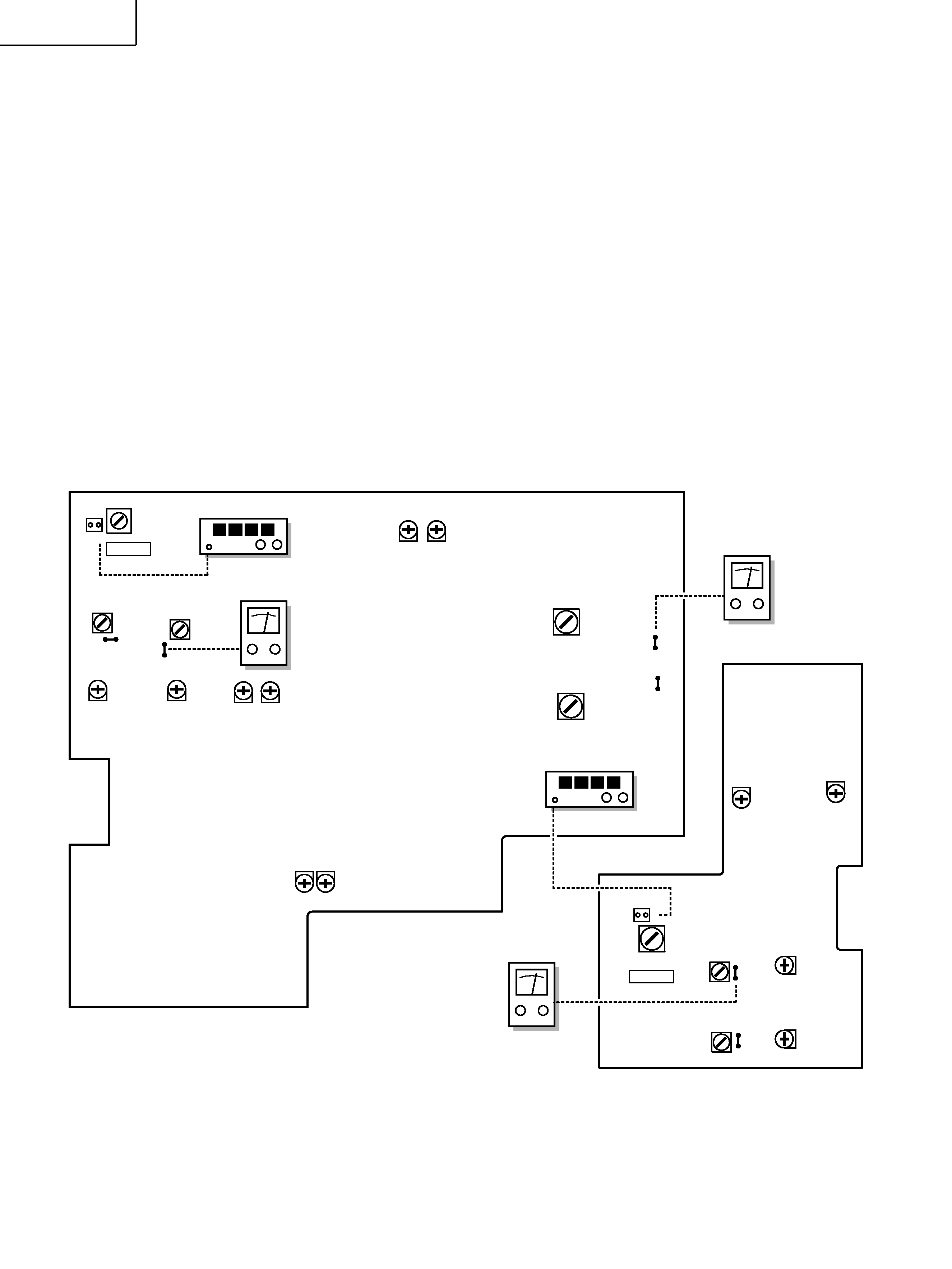
2-2-2 Adjustment locations
Fig. 2-2
L301
P303
12
L103
L203
100kHz
TP3
TP4
R14
R24
R12 R22
R13
L101
L201
R23
R11R21
TP1
TP2
MAIN PCB
P310
21
R51
R61
R52
L503
W39
TP
W40
TP
L603
R62
L401
REC AMP PCB
100kHz
W-860R
4
DC voltmeter
Frequency Counter
AC voltmeter
DC voltmeter
Frequency Counter
5
W-860R
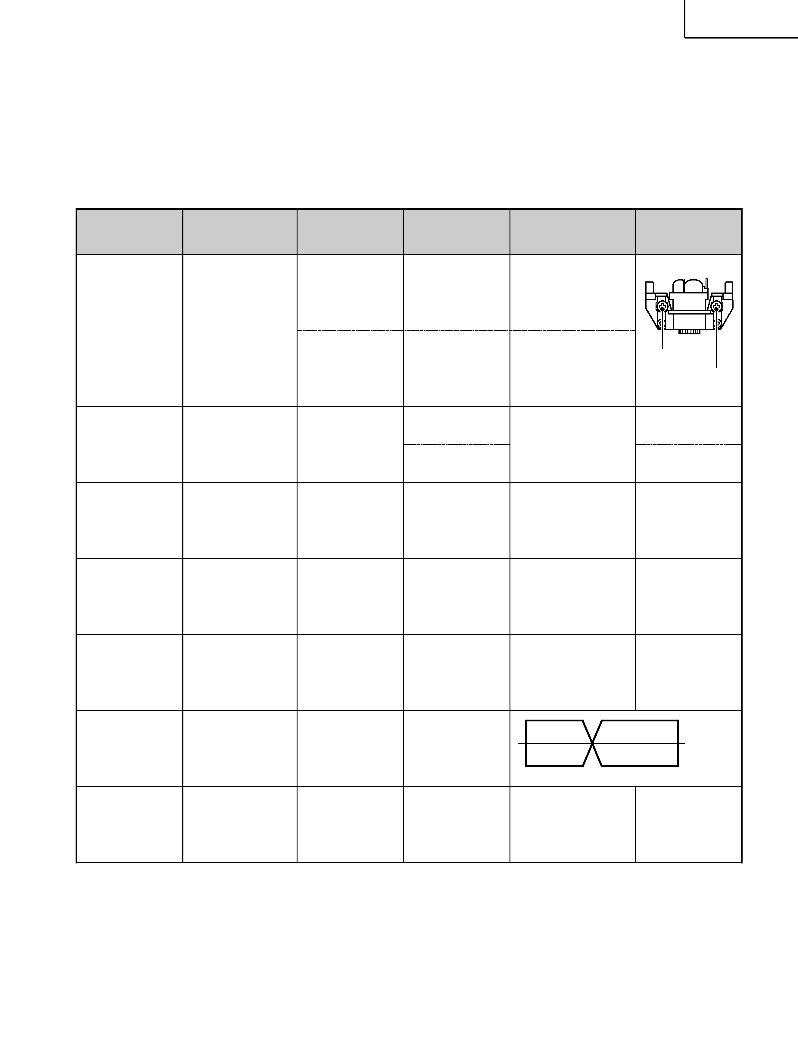
2-2-3 Playback performance
Deck settings:
TEAC test tapes:
Mode: PLAY
MTT-150C : For Dolby level calibration
DOLBY NR Switch: OFF
MTT-25702 : For playback frequency response check NORMAL tape
MTT-5513 : For S/N check NORMAL tape
ITEM
SETTING
INPUT SIGNAL
ADJUSTMENTS
MEASURING
POINTS, RESULT
REMARKS
1. Head
azimuth
adjustment
2. DOLBY level
REC/PLAY
3. Playback
output level
4. Meter level
5. PHONES
output level
6. Playback
frequency
response
7. Playback
S/N ratio
REC/PLAY
FWD azimuth
REV azimuth
250
1k
12.5k (Hz)
+4dB
4dB