w-790r
`
Thanks for buying a TEAC. Read this manual carefully to get the best
performance from this unit.
Nous vous remercions pour l'achat d'un appareil TEAC.
Lire ce manuel avec attention pour obtenir les meilleures performances
possibles de cet appareil.
Vielen Dank für den Kauf dieses TEAC-Geräts.
Bitte lesen Sie diese Anleitung sorgfältig durch, um die Leistungs-
fähigkeit dieses Geräts optimal nutzen zu können.
Grazie per aver acquistato un prodotto TEAC.
Leggere attentamente questo manuale per ottenere le migliori
prestazioni da questo apparecchio.
Enhorabuena por la adquisición de un TEAC.
Lea detenidamente este manual a fin de obtener el mejor rendimiento de
esta unidad.
Dank u voor de aanschaf van een TEAC.
Lees deze gebruiksaanwijzing aandachtig door teneinde de beste
prestaties van dit toestel te verkrijgen.
Double Cassette Deck
OWNER'S MANUAL ......................... 4
MANUEL DU PROPRIETAIRE ...........10
BEDIENUNGSANLEITUNG................16
MANUALE DI ISTRUZIONI ...............22
MANUAL DEL USUARIO ..................28
GEBRUIKSAANWIJZING ..................35
3D0021400A
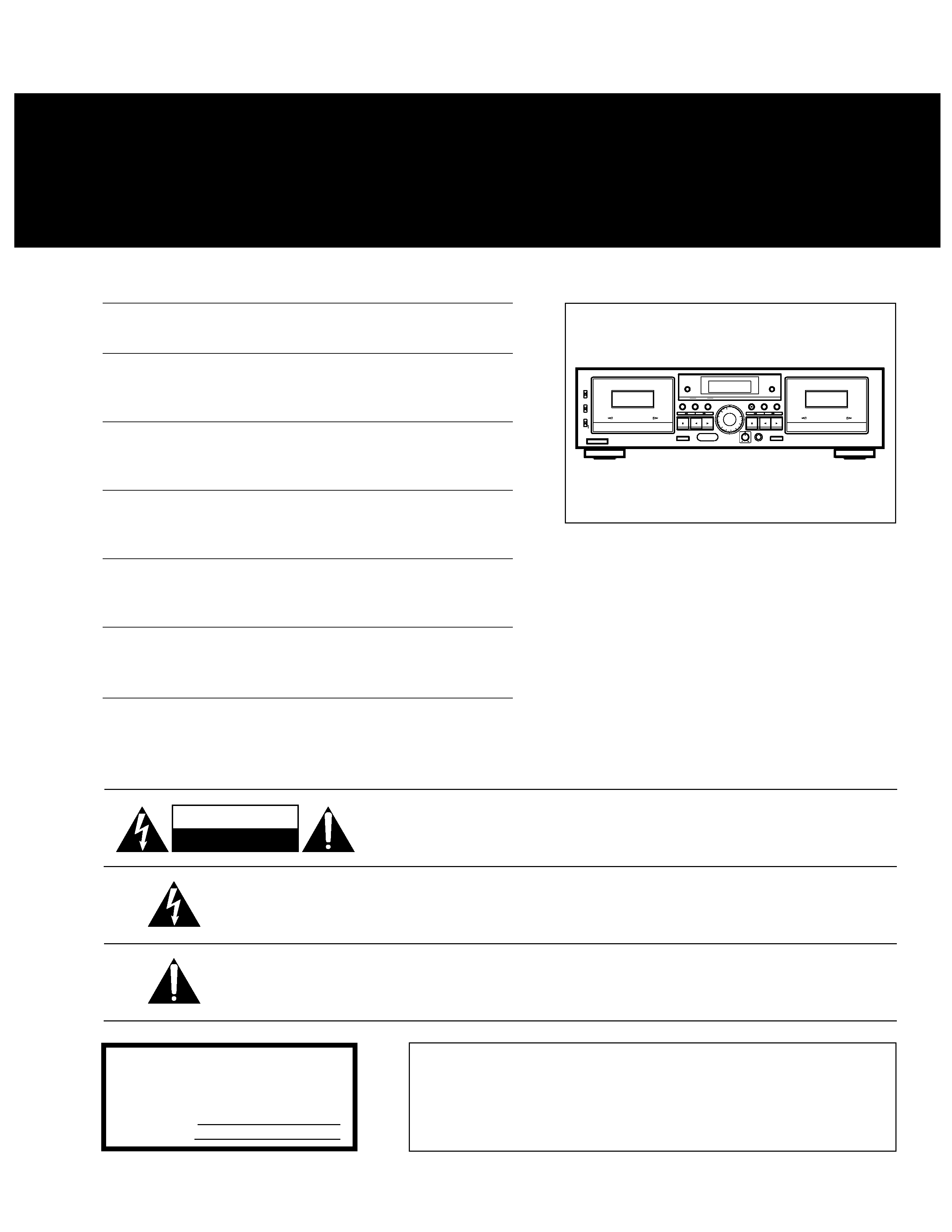
This appliance has a serial number located
on the rear panel. Please record the model
number and serial number and retain them
for your records.
Model number
Serial number
WARNING: TO PREVENT FIRE OR SHOCK
HAZARD, DO NOT EXPOSE THIS
APPLIANCE TO RAIN OR MOISTURE.
CAUTION: TO REDUCE THE RISK OF ELECTRIC SHOCK, DO NOT
REMOVE COVER (OR BACK). NO USER-SERVICEABLE PARTS
INSIDE. REFER SERVICING TO QUALIFIED SERVICE PERSONNEL.
The lightning flash with arrowhead symbol,within equilateral triangle,is intended to alert
the user to the presence of uninsulated"dangerous voltage" within the product's enclosure
that may be of sufficient magnitude to constitute a risk of electric shock to persons.
The exclamation point within an equilateral triangle is intended to alert the user to the
presence of important operating and maintenance (servicing) instructions in the
literature accompanying the appliance.
CAUTION
RISK OF ELECTRIC SHOCK
DO NOT OPEN
_ 2 _
Normal tapes
Bandes normales
Normalbänder
Nastri normali
Cintas normales
Normale cassettes
Chrome (Cobalt) Tapes
Bandes au chrome
(Cobalt)
Chrombänder (Kobalt)
Nastri al cromo (Cobalto)
Cintas de cromo (cobalto)
Chroom (kobalt) cassettes
Metal Tapes
Bandes métal
Metallbänder
Nastri di metallo
Cintas de metal
Metaalcassettes
Tape position identification holes
Trous d'identification de type de bande
Bandsorten-Identifikationsöffnungen
Fori di identificazione del tipo
Orificios de identificación del tipo de cinta
Bandsoortidentifikatiegaten
Within 7 m
Inférieur à 7 m
Innerhalb 7 m
A meno di 7 m
Dentro de los 7 m
Vanaf maximaal 7 m
Fig. 1
Abb. 1
Afb. 1
Connections/Raccordements de base/Grundsätzliche Anschlüsse/
Collegamenti di base/Conexiones básicas/Basisaansluitingen
Stereo Amplifier
Amplificateur stéréo
Stereo-Verstärker
Amplificatore stereo
Amplificador estereofónico
Stereo-versterker
Fig. 2
Abb. 2
Afb. 2
Fig. 3
Abb. 3
Afb. 3
Fig. 4
Abb. 4
Afb. 4
Fig. 5
Abb. 5
Afb. 5
W-790R
Fig. 6
Abb. 6
Afb. 6
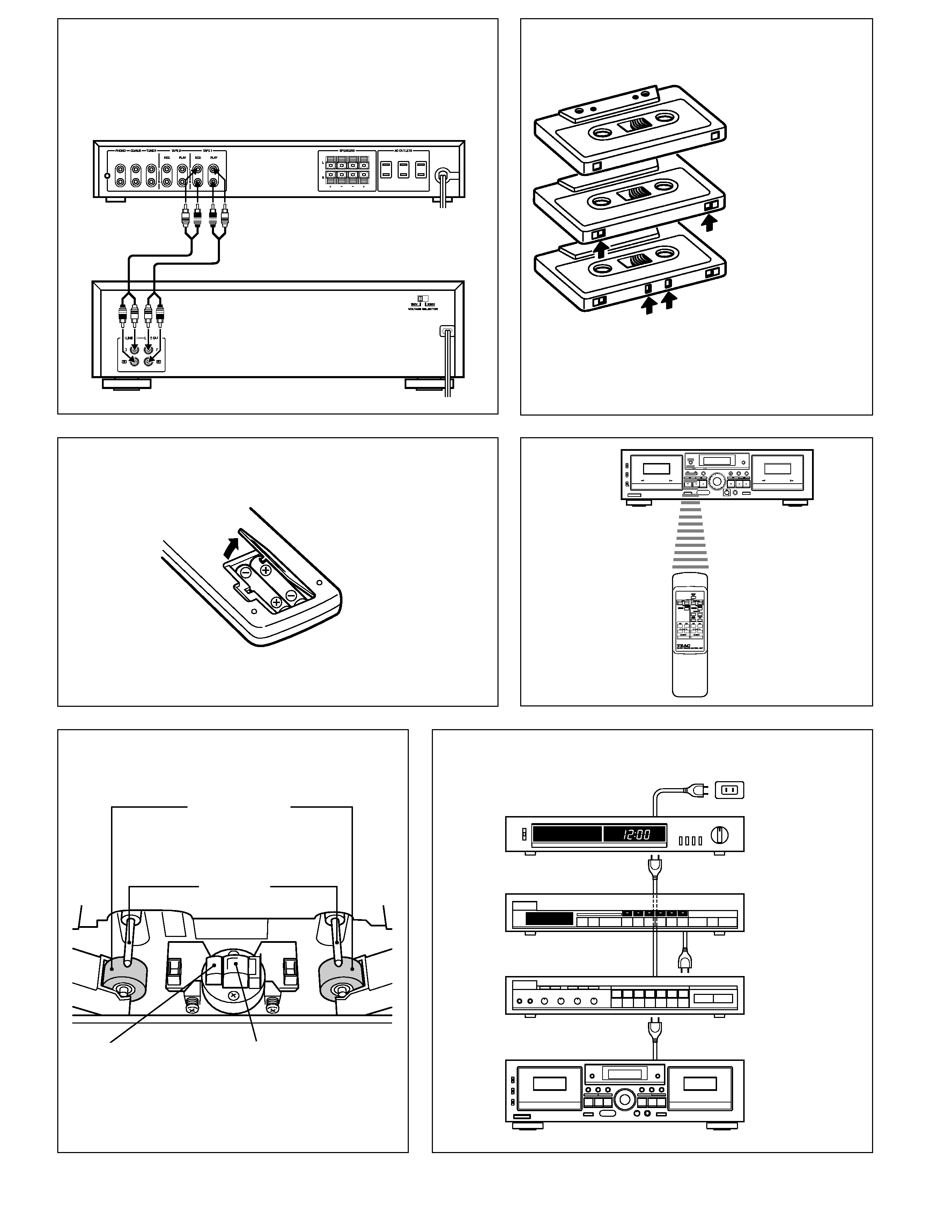
Pinch roller
Galet presseur
Andruckrolle
Rullo di presa
Rodillo de presión
Aandrukrol
Battery installation
Mise en place de piles
Einlegen der Batterien
Inserimento delle batterie
Cambio de pilas
Vervangen van de batterijen
Audio timer
Minuterie audio
Schaltuhr
Timer ad uso audio
Temporizador de audio
Audio-schakelklok
Tuner
Tuner
Tuner
Sintonizzatore
Sintonizador
Tuner
Amplifier
Amplificateur
Verstärker
Amplificatore
Amplificador
Versterker
AC power
Alimentation CA
Netz
Presa di corrente
Corriente alterna
Netspanning
Switched
Switched(commutée)
Geschaltet Switched
Asservita(Switched)
Switched(conmutado)
Switched
Spare AC outlet
Prise CA de rechange
Zusätzliche Netzsteckdose
Presa di servizio
Tomacorriente CA auxiliar
Extra spanning suitgang
Capstan
Cabestan
Capstan
Cabestano
Cabrestante
Windas
Erase head
Tête d'effacement
Löschkopf
Testina di cancellazione
Cabeza de borrado
Wiskop
Record/playback head
Tête d'enregistrement/lecture
Aufnahme/Wiedergabe-Kopf
Testina di
registrazione/riproducción
Cabeza de
grabación/reproducción
Opname/weergavekop
W-790R
_ 3 _
Fig. 7/Abb. 7/Afb. 7
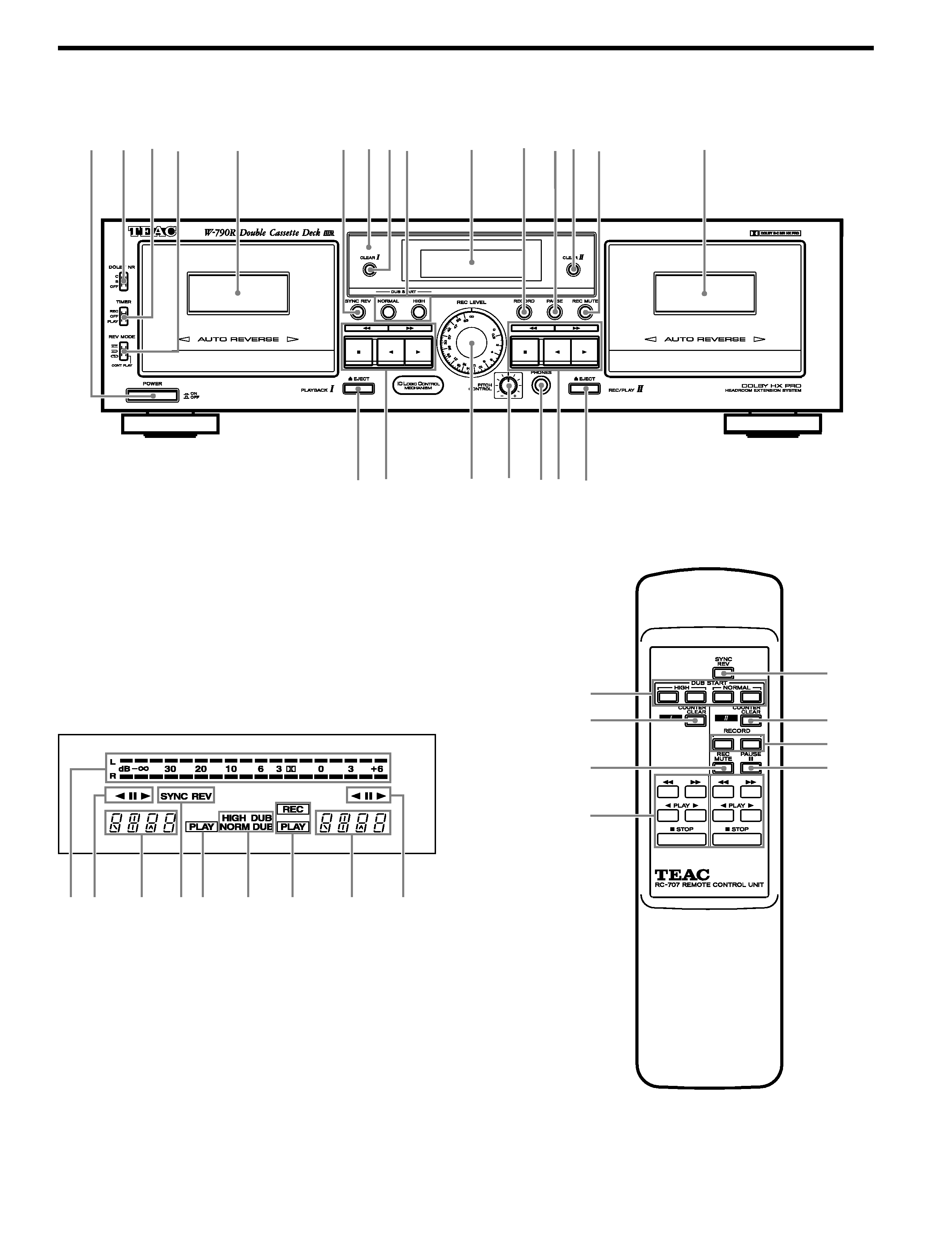
Front Panel/Panneau avant/Frontplatte/Pannello anteriore/Panel frontal/Voorpaneel
Reference Illustrations/Illustrations de référence/Bezugsabbildungen/Illustrazioni di riferimento/
Illustraciones de referencia/Referentieafbeeldingen
1
23
5
4
tr
yu i
r t
8
7
8
9
0q we
6
5
6
q
w
8
9
8
e
t
Remote Control Unit
Boîtier de télécommande
Fernbedienung
Unità per il comando a distanza
Unidad de control remoto
Afstandsbedieningseenheid
Display
Fenêtre d'affichage
Displayfeld
Displayvenster
`1
2
3 4
5
4
2
1
Features and Controls (Fig. 7)
Environment
Avoid using the deck in the following
conditions:
At high temperatures (near a heater,
exposed to direct sunlight, etc.).
At extremely low temperatures.
Where there is excessive humidity.
In a dusty atmosphere.
Where power line voltage fluctuations
are severe (in which case the use of a
voltage regulator may be advisable).
Cassette Tape (Fig.2)
Tape Selection:
For the automatic tape select function to
work properly, metal and chrome (cobalt)
tapes must have identification holes.
Tape Handling:
Do not store tapes in the following places:
On top of heaters, exposed to direct
sunlight or in any other places with high
temperatures.
Near speakers, on TV sets or amplifiers
or where they would be exposed to
strong magnetic fields.
Where humidity is high and in dirty,
dusty places.
Avoid dropping or subjecting cassettes
to excessive shocks.
1 Power Switch
Note: If you switch the power off, be sure
to wait for more than 3 seconds before
switching it on again.
2 DOLBY NR Select Switch
OFF : Set to this position when you do not
want to use any noise reduction
system.
B : Set to this position when making a
recording using the Dolby B noise
reduction system, or playing back
tapes recorded with Dolby B NR.
C :
Set to this position when making a
recording using the Dolby C noise
reduction system, or playing back
tapes recorded with Dolby C NR.
3 TIMER Switch
(See page 8.)
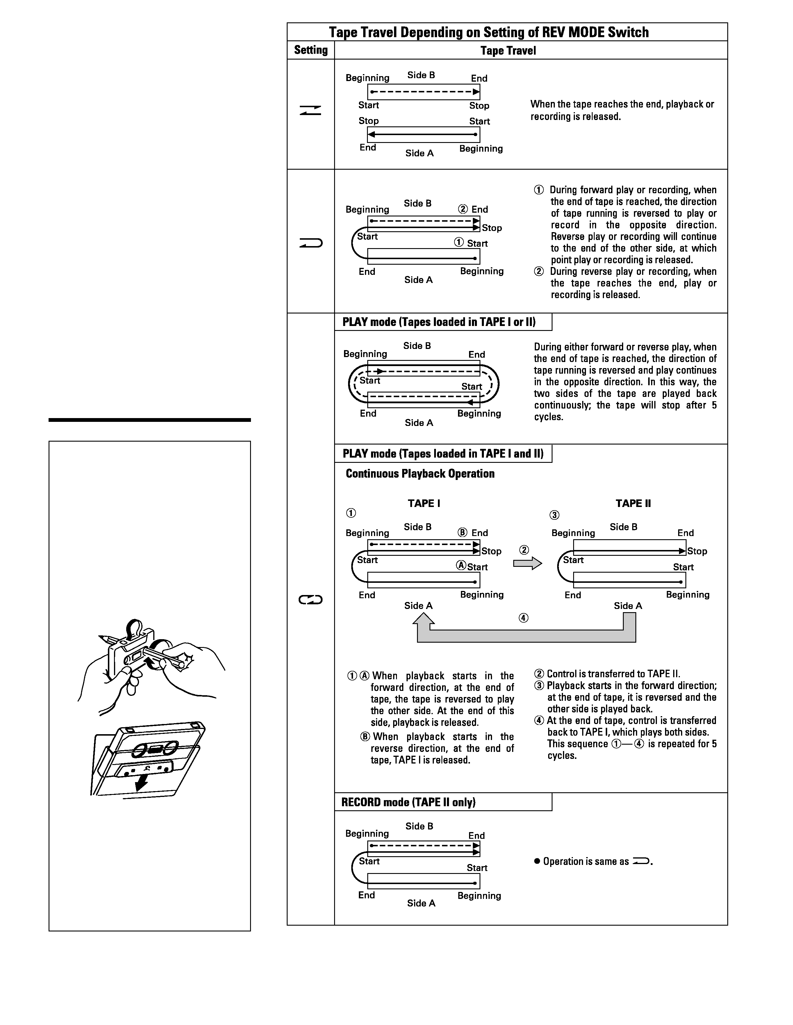
4 REV (Reverse) MODE Switch
(See page 5.)
5 Cassette Holder
(TAPE I/TAPE II)
(See page 5.)
6 SYNC REV (Reverse) Button
(See page 7.)
7 REMOTE SENSOR
(Infrared Signal Reception Window)
8 COUNTER CLEAR Button
(TAPE I/TAPE II)
Pressing the COUNTER CLEAR Button
resets the multi-counter to "0000".
9 DUB (Dubbing) START Button
(See page 6.)
To enter the dubbing mode using the
remote control, press the two DUB START
buttons simultaneously.
0 Display Window
` Peak Level Meter
1 Direction & Pause Indicators
2 Multi Counter
3 SYNC REV Indicator
4 Mode Indicators
5 Dubbing Indicators
q RECORD Button (TAPE II only)
(See page 7.)
To enter the record mode using the remote
control, press the two RECORD buttons
simultaneously.
_ 4 _
Precautions
Front Panel/Remote Control Unit
Connections (Fig.1)
Turn off the power switches of all
equipment before making connections.
Read the instructions of each
component you intend to use with the
deck.
LINE OUT terminals
LINE OUT Terminals on the tape deck
should be connected to the TAPE PLAY or
LINE IN jacks on the amplifier/receiver.
LINE IN terminals
LINE IN Terminals on the tape deck should
be connected to the REC OUT jacks on the
amplifier/receiver.
Power cord
Be sure to connect the power cord to an
AC outlet which supplies the correct
voltage, as set by the voltage selector.
IMPORTANT (for U.K. Customers)
DO NOT cut off the mains plug from this
equipment. If the plug fitted is not
suitable for the power points in your
home or the cable is too short to reach
a power point, then obtain an
appropriate safety approved extension
lead or consult your dealer.
If nonetheless the mains plug is cut off,
remove the fuse and dispose of the plug
immediately, to avoid a possible shock
hazard by inadvertent connection to the
mains supply.
If this product is not provided with a
mains plug, or one has to be fitted, then
follow the instructions given below:
IMPORTANT. DO NOT make any
connection to the larger terminal which
is marked with the letter E or by the
safety earth symbol ç or coloured
GREEN or GREEN-and-YELLOW.
The wires in the mains lead on this
product are coloured in accordance
with the following code:
BLUE: NEUTRAL
BROWN:
LIVE
As these colours may not correspond
with the coloured markings identifying
the terminals in your plug proceed as
follows:
The wire which is coloured BLUE must
be connected to the terminal which is
marked with the letter N or coloured
BLACK.
The wire which is coloured BROWN
must be connected to the terminal
which is marked with the letter L or
coloured RED.
When replacing the fuse only a
correctly rated approved type should
be used and be sure to re-fit the fuse
cover.
IF
IN
DOUBT
--
CONSULT
A
COMPETENT ELECTRICIAN.
*Dolby noise reduction and HX Pro
headroom extension manufactured under
license
from
Dolby
Laboratories
Licensing Corporation. HX Pro originated
by Bang & Olufsen.
"DOLBY", the double-D symbol and
"HX PRO" are trademarks of Dolby
Laboratories Licensing Corporation.
w PAUSE Button (TAPE II only)
e REC (Record) MUTE Button
(TAPE II only)
(See page 7.)
r EJECT Button (TAPE I/TAPE II)
t Tape Operation Buttons
(TAPE I/TAPE II)
: Rewind/CPS Button
Ò : Fast Forward/CPS Button
: STOP Button
"
: Reverse Play Button
: Forward Play Button
y REC (Record) LEVEL Control
(TAPE II only)
(See page 7.)
u PITCH CONTROL (TAPE I only)
(See page 6.)
i PHONES Jack
Connect 8-ohm stereo headphones to this
jack for private listening or monitoring.
_ 5 _
Operations
Loading a Cassette Tape
1. Use your finger or a pencil to turn the
cassette's hub and take up any slack
tape.
Note: Avoid touching the tape.
Fingerprints attract dust and dirt.
2. Press the eject button ()* to open
the cassette compartment door.
3. Load the cassette tape with its open
edge facing down.
4. Gently close the compartment door.
*Notes:
The cassette holder cannot be opened
during recording or playback.
If the power has been switched off
during play or recording, ejecting the
cassette may be impossible. In such a
case, switch the power on and press
the eject button again.