
TASCAM 788 Brief Guide
1
A Brief Guide to the 788
Unpacking your 788
When you unpack your 788, you should find, in addi-
tion to this sheet:
· The 788 itself
· A power adaptor (PS-P788) for your local voltage
· Two balanced XLR to balanced 1/4-inch stereo jack
adaptors for use when recording using balanced
sound sources
·An OPERATIONAL TUTORIAL manual
·An Owner's Manual
· A 788 Road Map
If any of these items are missing, you should contact
your TASCAM distributor.
Retain the carton and any packing materials, in case
you need to transport the 788 to another location at a
future date.
Setting up the 788
This is fully described in the other documentation,
but take careful note of the following points:
· The 788 contains a hard disk. Like the hard disks in
laptop and notebook computers, it is quite robust,
but when the unit is in operation, sudden shocks
and vibration may damage the hard disk, causing
possible loss of data. Always make sure that the
788 is mounted on a stable, level surface. Treat the
788 as you would a notebook or laptop computer,
and you should have no cause for concern,
· The underside of the 788 can become quite hot in
normal operation. This does not indicate a fault, but
you should be aware of this when picking up the
788 after it has in operation for some time. In addi-
tion, we strongly recommend that the surface on
which the 788 is mounted is a firm, non-uphol-
stered surface. Avoid standing the 788 on carpets,
rugs, cloth coverings, etc.
· Always make and break connections to and from
the 788 with the power to all units turned OFF.
This is especially true of SCSI devices. If you are
connecting or disconnecting a SCSI device (remov-
able disk, hard disk, CD-R drive), etc. to or from
the 788, you should turn off the power to the 788
and the SCSI device before making or breaking the
connection.
· When powering up the system, any SCSI devices
should be turned on before the 788. Audio sources
should be turned on before the 788, which should
be turned on before the monitoring system.
Loading and playing the demonstration song
1
Connect the 788 MONITOR OUTPUTs to your
monitoring system (or plug headphones into
the PHONES jack). Turn the MONITOR
LEVEL
control 7 fully counterclockwise,
2
Turn on the 788, and then turn on the moni-
toring system. Turn up the volume of the
monitoring system and turn the MONITOR
LEVEL
control 7 clockwise about halfway.
3
When the 788 has finished its start up (taking
about 30 seconds), press the MENU key I.
4
Use the dial W to highlight SONG and press
ENTER e
.
5
Use the dial to highlight LOAD, and press
ENTER
.
6
Use the dial to highlight LIQUOR
STORE, and press ENTER.
7
When the song has loaded, press the QUICK
SETUP
key 4.
8
Use the dial to highlight MIXDOWN, and
press ENTER.
9
Press the HOME/ESC key J.
10
Press the MONITOR SELECT key E so that
the STEREO indicator lights.
11
Press PLAY j to start playing back the song.
12
The channel faders X can be used to adjust
the individual disk tracks, and the STEREO
fader Y adjusts the overall level. The on-
screen meters show the level.
13
Use the MONITOR LEVEL control to adjust
the monitoring level.
You can experiment with the EQ settings, effects, etc.
as described in the other manuals provided with the
788.
9101436900
Front panel features
2 TASCAM 788 Brief Guide
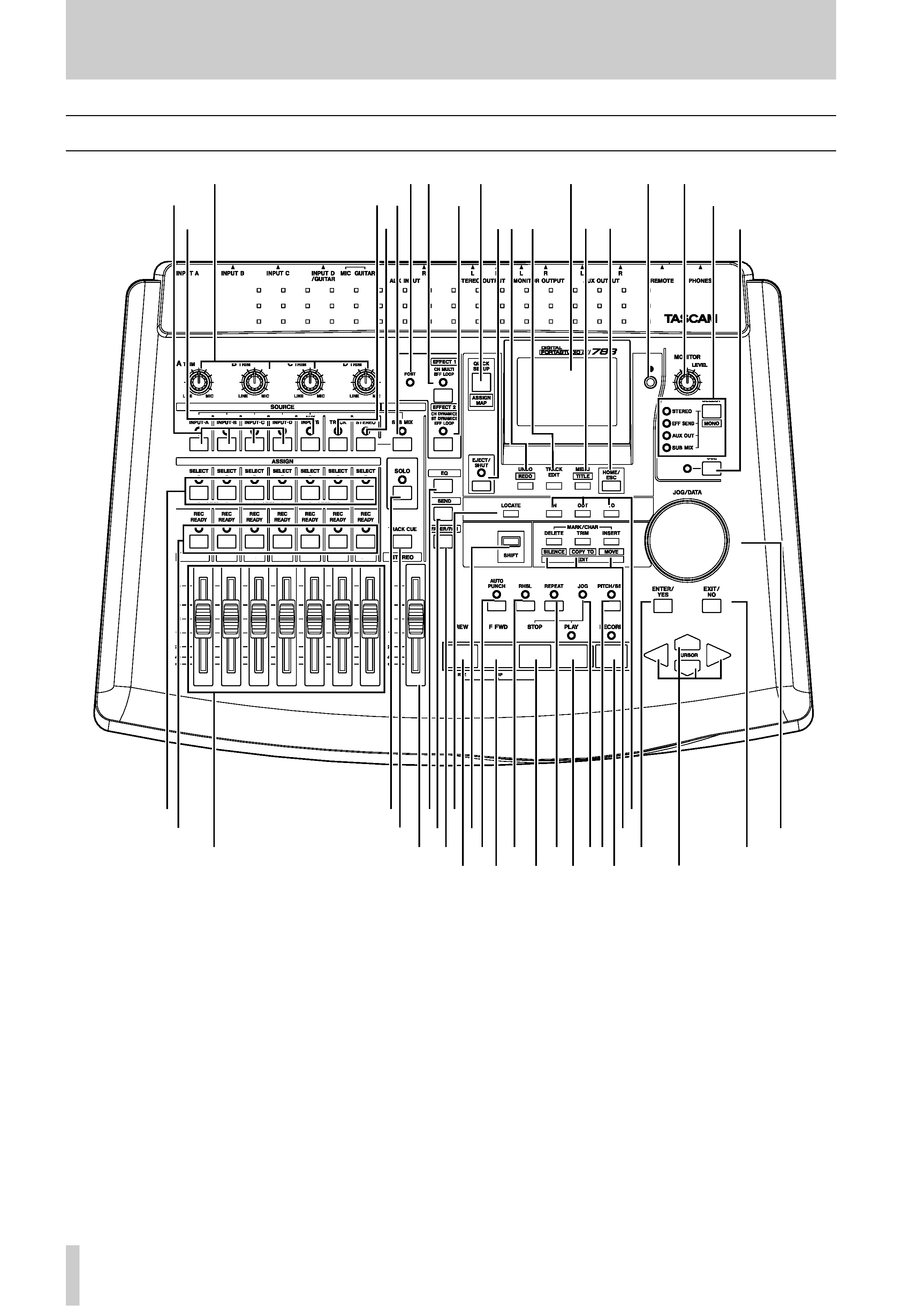
Front panel features
Because the 788 relies so much on its internal soft-
ware for control, many of the features described here
have one or more functions.
This section is not intended as a complete guide to
the operation of the 788, but should give you an idea
of the basic use of the controls and connectors on the
front and rear panels.
1 TRIM controls Control the level from the
analog inputs to the assigned mixer channels.
2 POST indicator Shows the pre/post set-
tings of the internal effectors.
3 EFFECT 1 key and indicator Controls
and shows the settings and assignments of the first
internal effector.
4 QUICK SETUP/ASSIGN MAP key Con-
trols settings and display of routing and assignments,
etc. as well as library functions.
5 Display screen (backlit) Shows settings
and parameters.
6 Contrast control Controls the contrast of
the display screen.
7 MONITOR LEVEL control Controls the
level of the signals from the MONITOR OUTPUTS
and PHONES.
L
QR
12 3
4
5
6
7
9
B
8
AC
DE
H
K
FG
IJ
M
NO
P
SU
V
W
T
XY
Z
a
b
cd
e
f
gh
i
j
k
l

Front panel features
TASCAM 788 Brief Guide
3
8 INPUT (AD) keys and indicators
Control and show the assignment of inputs A through
D
to the mixer channels.
9 AUX INPUTS key and indicator Con-
trols and shows the assignment of the AUX INPUTS
to the mixer channels.
A TRACK key and indicator Control and
show the assignment of recorded tracks to the mixer
channels and virtual tracks to active tracks.
B STEREO key and indicator Control and
show the assignment related to the STEREO pair of
channels as well as settings for these channels
C SUB MIX key and indicator Control and
show the assignment of the 788's internal sub-mixer,
as well as the settings for the sub-mixer.
D EFFECT 2 key and indicator Controls
and shows the settings and assignments of the second
internal effector.
E MONITOR SELECT key and
indicators Controls and show the signals that are
sent from the MONITOR OUT and PHONES jacks.
Shifted, this key allows mono monitoring.
F EJECT/SHUT key and indicator Used
to shut down the 788, and eject removable media,
and to show the status of the shutdown process.
G UNDO [REDO] key Used to control the
undo and redo of recording, editing operations, etc.
H TRACK EDIT key Used to enter the non-
destructive track editing functions (cut, move, etc.).
I MENU [TITLE] Used unshifted to enter the
system menus. Shifted, this key enters titling mode
(songs, library entries, virtual tracks, etc.).
J HOME/ESC key Returns the display to the
"home" screen.
K CUE key and indicator Controls and
shows the replay of the track cue signals from the
MONITOR OUTPUTS
and PHONES connectors.
L SELECT keys and indicators Used to
assign inputs to mixer channels, to link channels in
stereo pairs, to select channels for parameter adjust-
ment and soloing, tracks for virtual track assignment,
etc.
M SOLO key and indicator Used to select
and show the status of mixer channels selected for
soloing.
N EQ key Used to bring up the channel equal-
ization adjustment screen.
O LOCATE key Used to recall the list of mem-
ory location points. When shifted, used to input a
memory location point.
P IN, OUT and TO keys Used with three spe-
cial location points for auto punch, repeat playback,
location, and track editing purposes. Unshifted, these
keys locate to the playback points. Shifted, they are
used to set the playback points.
Q REC READY keys and indicators Used
to set and display the recording status of the tracks.
R TRACK CUE key Used to bring up the
screen controlling the level and pan of recorded
tracks to the track cue monitoring subsystem.
S SEND key Used to bring up the screens con-
trolling the level, etc. of the channel sends and master
sends to the Aux and Effect send loops.
T FADER/PAN key Used to bring up the
screen controlling pan settings, and providing the
fader view (for use when physical and internal fader
positions do not match).
U SHIFT key Used with other keys to provide a
secondary function. When used, the SHIFT key is
always pressed and held down while the other key is
pressed.
V MARK/CHAR [EDIT] (DELETE
[SILENCE], TRIM [COPY TO], INSERT
[MOVE] keys Used unshifted to insert/delete
characters in titles, add/remove selections from lists,
and to enter/edit/remove location memories. Used
shifted as short cuts to commonly-used track editing
functions.
W JOG/DATA dial Used to adjust the playback
position (in jog mode) and to edit parameter data.
X Channel faders Used to adjust the output
level from the channels (channels 7 and 8 are always
linked together). The 0 fader setting represents the
nominal level.
Y STEREO fader Used to adjust the level of
the stereo mixed signals from the STEREO
OUTPUT
s and from the DIGITAL OUTPUT. The 0
fader setting represents the nominal level.
Z AUTO PUNCH key and indicator Used
to set and display the current auto punch status when
punching new material into previously-recorded
material.
a RHSL key and indicator Used to set and
display the status of the rehearsal facility used in
recording (including auto punch modes).
Rear panel
4 TASCAM 788 Brief Guide
b REPEAT key and indicator Used to set
and show the status of repeat playback and recording,
as well as to set the gap between repeats.
c JOG indicator Lights when jog (trim) mode
is in operation, as set by the STOP+PLAY key combi-
nation.
d PITCH/SSA key and indicator Used to
set and display the status of varispeed (pitch control)
as well as the SSA (Slow Speed Audition) function.
e ENTER/YES key Used to "go down a level"
in the menu system, to confirm settings, or to give a
positive answer to questions asked by the 788.
f EXIT/NO key Used to "go up a level" in the
menu system, to exit without making settings, or to
give a negative answer to questions asked by the 788.
g REW key Used to move the playback position
backwards in the song. Also used with STOP to
locate to the zero point.
h F FWD key Used to move the playback posi-
tion forwards in the song. Also used with STOP to
locate to the last recording position.
i STOP key Stops playback, recording or
"winding". Used with PLAY for jog mode.
j PLAY key Starts playback. Uses with
RECORD
for recording.
k RECORD key Use with PLAY for recording.
l Cursor keys Used to navigate around menu
and parameter setting screens to highlight parame-
ters, options, etc.
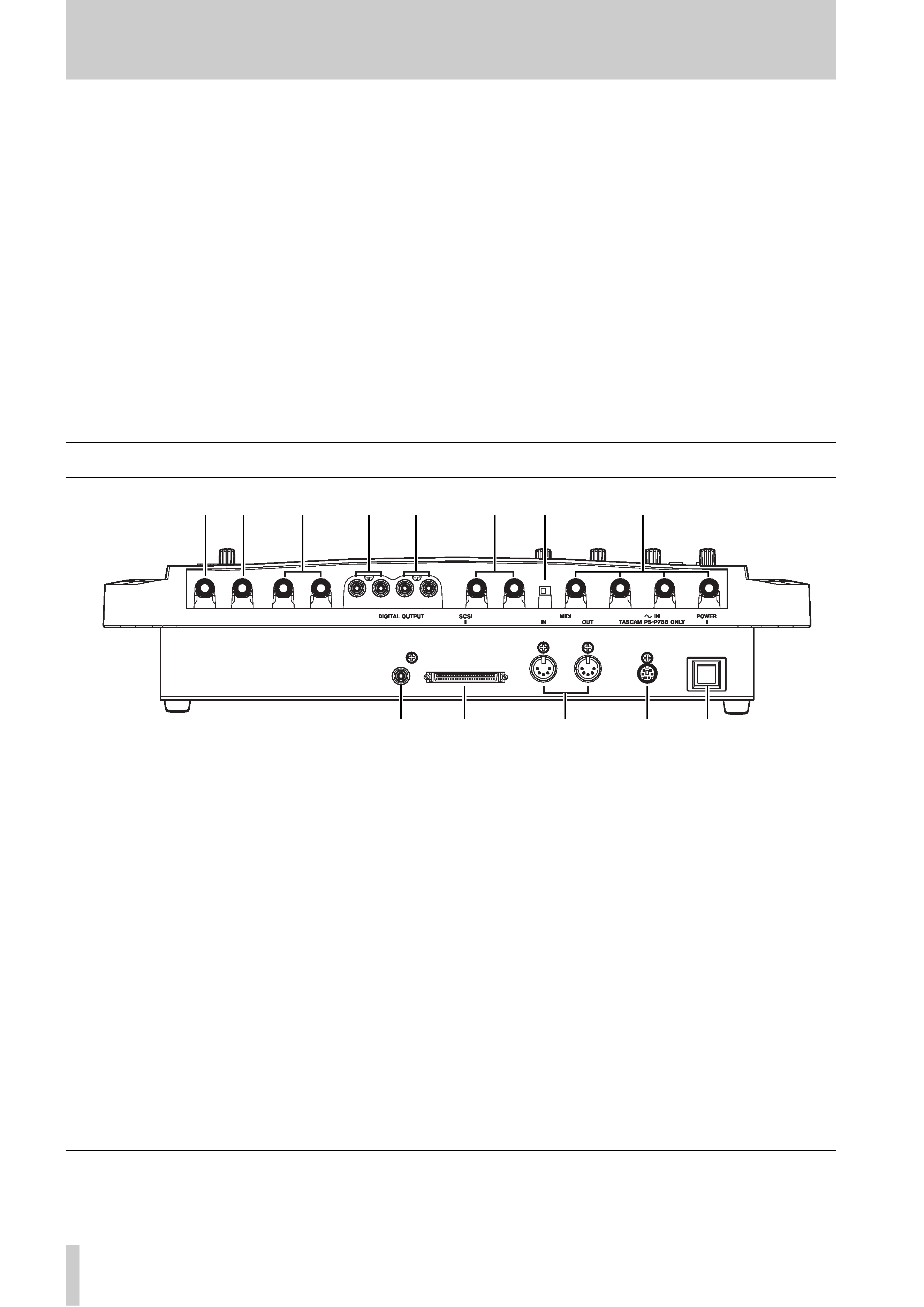
Rear panel
m PHONES jack Used with standard stereo
headphones (1/4" jack).
n REMOTE jack 1/4" jack used with a foot-
switch such as the TASCAM RC-30P for hands-free
punch operations.
o AUX OUTPUT jacks Output unbalanced
signals from the Aux loop at 10 dBV. Connect to the
L
output only for mono.
p MONITOR OUTPUT jacks Output the
selected monitor signals. RCA (phono) jacks at a
level of 10 dBV.
q STEREO OUTPUT jacks Output the
mixed stereo signals. RCA (phono) jacks at a level of
10 dBV.
r AUX INPUT jacks Accept 10 dBV unbal-
anced signals (1/4" jacks) to the Aux input channels
for assignment to mixer channels or the sub-mixer.
s MIC/GUITAR switch Switches the input
impedance of INPUT D between MIC/LINE (MIC)
and a value suitable for electric guitars, basses, etc.
(GUITAR).
t INPUTS A through D Accept 50 dBu to
+4 dBu balanced signals. Use the supplied XLR-to-
phone convertors to connect XLR-equipped sources.
u DIGITAL OUTPUT Outputs the mixed ste-
reo signals in digital audio IEC60958 TYPE II
(SPDIF) format from a coaxial RCA connector.
v SCSI connector SCSI-2 connector for con-
nection of external storage devices, CD-R drives, etc.
w MIDI IN and OUT Accept and transmit
MIDI information as described in the manuals.
x POWER IN Connect this only to a PS-P788
power supply unit where the voltage requirements
match your local power supply.
y POWER switch Press to turn on, and press
again to turn off after shutting down the 788 using
the EJECT/SHUT key F as described in the
manuals.
TEAC CORPORATION
Phone: (0422) 52-5082
3-7-3, Nakacho, Musashino-shi, Tokyo 180-8550, Japan
uv
w
x
y
no
p
q
r
t
ms
Printed in Taiwan MA-0407