SERVICE MANUAL
SR-L50
CD Receiver
NOTES
CONTENTS
PC boards shown are viewed from parts side.
1 SAFETY INFORAMTION........................
2
Parts marked with * require longer delivery time.
2 SPECIFICATIONS.................................
3
3 ADJUSTMENT AND CHECKS.................
4
The parts with no reference number or no parts number in the
exploded views are not supplied.
3-1 TUNER SECTION...............................
4
3-2 CD SECTION.....................................
7
As regards the resistors and capacitors, refer to the circuit
diagrams contained in this manual.
4 EXPLODED VIEWS AND PARTS LIST......
8
Parts marked with this sign are safety critical
5 PC BOARDS AND PARTS LIST...............
16
components. They must be replaced with identical
6 WIRING DIAGRAM................................
26
components refer to the appropriate parts list and
ensure exact replacement.
Parts of [] mark can be used only with the version designated.
[T/C]:USA/CANADA,[EUR]:EUROPE,[UK]:UK,
[HKG]:HONG KONG
SR-L50
1 SAFETY INFORMATION
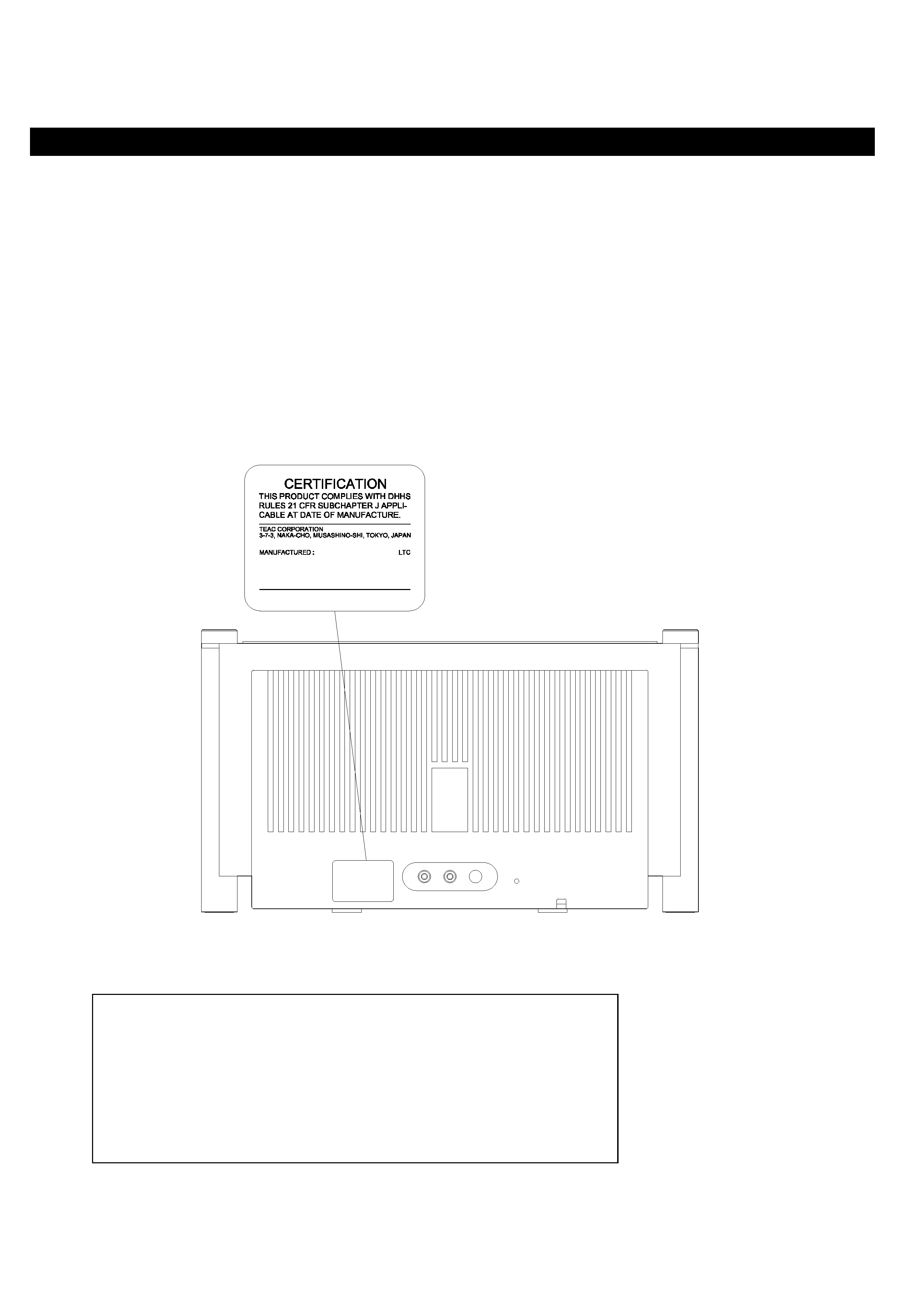
SAFETY INFORMATION
This product has been designed and manufactured according to FDA regulations "title 21, CFR, chapter 1,
subchapter J based on the Radiation Control for Health and Safety Act of 1986" and is classified as class 1 laser
product. There is no hazardous invisible laser radiation during operation because invisible laser radiation emitted
inside of this product is completely confined in the protective housings. The label required in this regulation is shown
below.
CAUTION
USE OF CONTROLS OR ADJUSTMENT OR PERFORMANCE OF PROCEDURES OTHER THAN THOSE
SPECIFIED HERE IN MAY RESULT IN HAZARDOUS RADIATION EXPOSURE.
Optical pickup:
Type
:
SLD104AU
Manufacturer
:
SONY Corporation
Laser output
:
Less than 0.5mV on the objective lens
Wavelength
760 800 nm
2

SR-L50
2 SPECIFICATIONS
TUNER Section (FM)
GENERAL
Frequency Range.................. 87.50 to 108.00 MHz(100kHz step)
Total Output Power......................................................15W
(U.S.A./Canada Model, General Export Model)
Power Requirements...........120V, 60Hz (U.S.A./Canada model)
Frequency Range.................... 87.50 to 108.00 MHz(50kHz step)
230V, 50Hz (Europe Model)
(Europe Model)
120V/230V AC, 50-60Hz (General export model)
Power Consumption......................................................40W
TUNER Section (AM)
Dimension ( W x H x D ) ..........................389 x 213 x 216 mm
Frequency Range...........................520 to 1710 kHz(10kHz step)
(15-7/8" x 8-3/8" x 8-1/2")
(U.S.A./Canada Model, General Export Model)
Weight.....................................................6.0 kg (13-3/16 lb)
Frequency Range.............................522 to 1620 kHz(9kHz step)
(Europe Model)
Standard Accessories
Remote Control Unit (RC-917) x 1
CD PLAYER Section
FM lead-type antenna
Frequency Response...................................20 to 20kHz (±1dB)
(U.S.A./Canada Model, General Export Model)
Wow and Flutter.................................................Unmeasurable
Remote Control Unit (RC-917) x 1
(Europe Model)
SPEAKER SYSTEM Section
Type.............................................................65 mm 1-way x2
80 mm subwoofer x1
Design and specifications are subject to change without notice.
Impedance.......................................................8 ohms (L & R)
Illustrations may differ slightly from production models
8 ohm (subwoofer)
3
SR-L50
3 ADJUSTMENTS AND CHECKS
3-1 TUNER SECTION
Use a screwdriver with a plastic or ceramic grip for all adjustment.
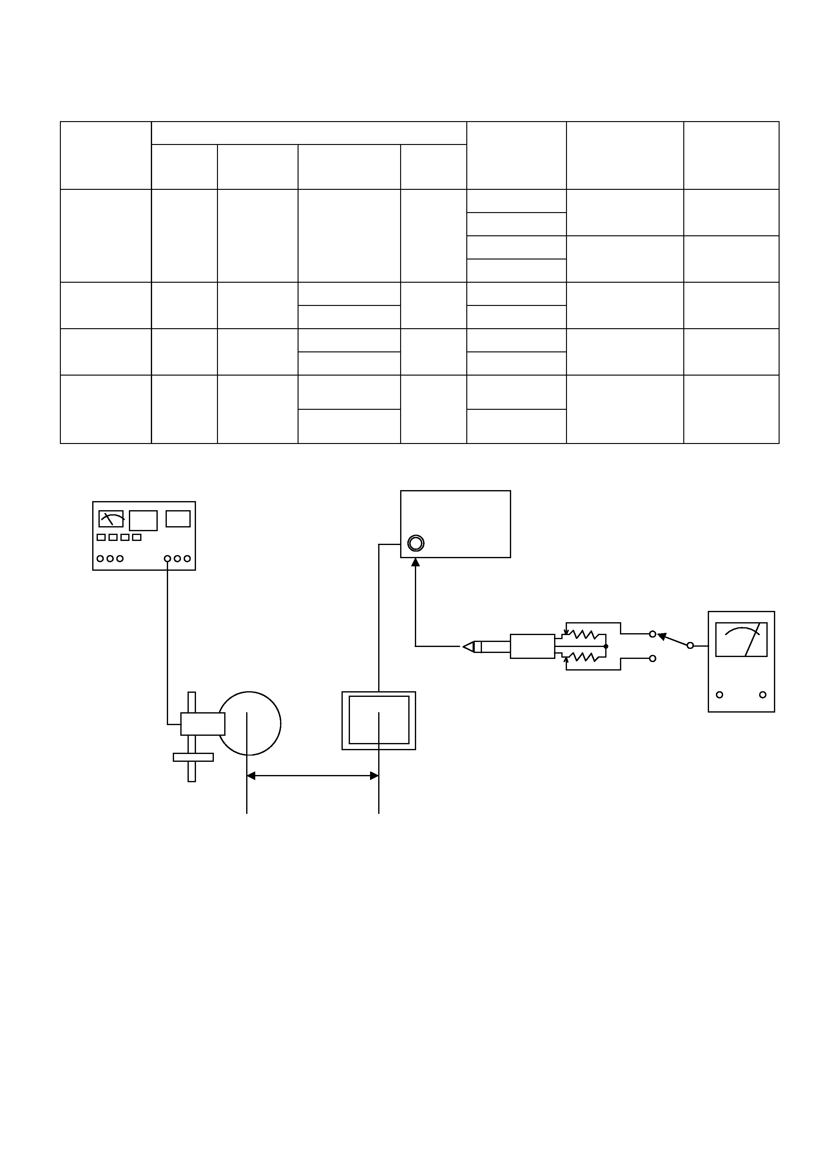
AM adjustment
1. Set the function switch to the TUNER position.
2. Set the BAND switch to the AM position.
3. Connect the test loop antenna across the output of the signal generator.
4. Connect the oscilloscope to the PHONES JACK terminal.
5. Set the signal generator as listed in the alignment chart.
FM adjustment
1. Set the function switch to the TUNER position.
2. Set the BAND switch to the FM position.
3. Connect the signal generator output through a 75 ohm dummy antenna to "ANT"
on TUNER PCB CN8.
4. Connect the oscilloscope to the PHONES JACK terminal.
5. Set the signal generator as listed in the alignment chart.
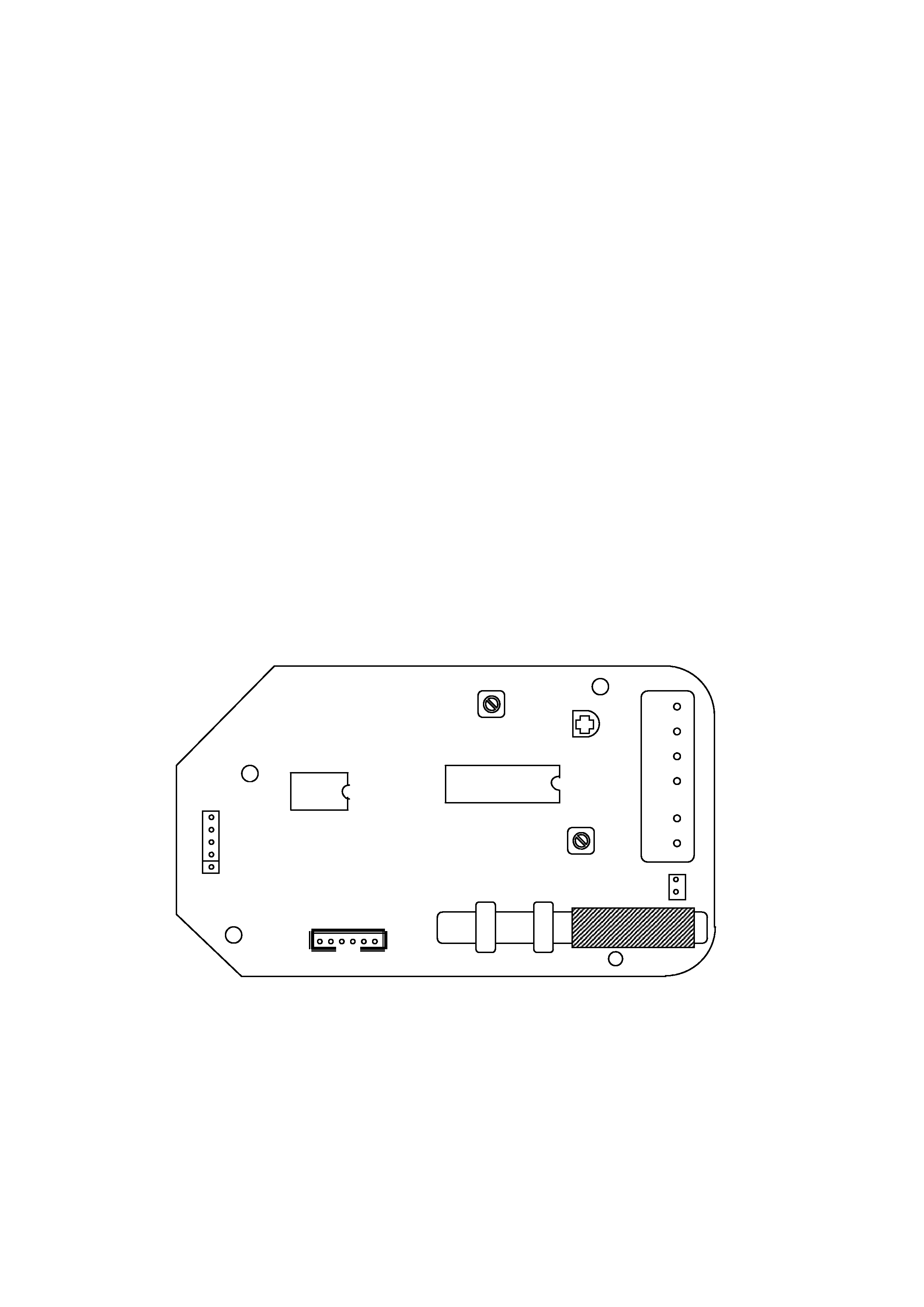
3-1-1. RADIO ALIGNMENT
FIG. 1-1 Adjustment locations
4
TUNER
P
A
CK
TC
1
CW1
1
CN10
CW8
L5
L4
IC2
L3
IC1 TA2057N
SR-L50
TUN
E
R
PCB
SR-L50
3-1-2 AM TUNER
SG SETT I NG
ITEM
Audio
Modulation
Frequency
Output
TUNER
SETTING
ADJUSTMENTS
MEASURING
POINTS
RESULT
1710KHz(T/C)
1620KHz(EUR)
L4
VT
8.0V
530KHz(T/C)
1.VOLTAGE
adjustment
531KHz(EUR)
Check
VT
1.5V
610KHz(T/C)
610KHz(T/C)
2.IFT
adjustment
1KHz
30%
612KHz(EUR)
76dBuV
612KHz(EUR)
L5
Maximum
output level
610KHz(T/C)
610KHz(T/C)
3.ANT Coil
adjustment
1KHz
30%
612KHz(EUR)
76dBuV
612KHz(EUR)
Am ant coil
L3
Maximum
output level
1410KHz(T/C)
1410KHz(T/C)
4.TC1
adjustment
1KHz
30%
1413KHz(EUR)
76dBuV
1413KHz(EUR)
TC1
Repeat step 3
and 4
Maximum
output level
AM Signal generator
AM
AC voltmeter
AM LOOP
Antenna
60CM
FIG. 1-1-1
5
SR-L50
PHONES
1K
1K