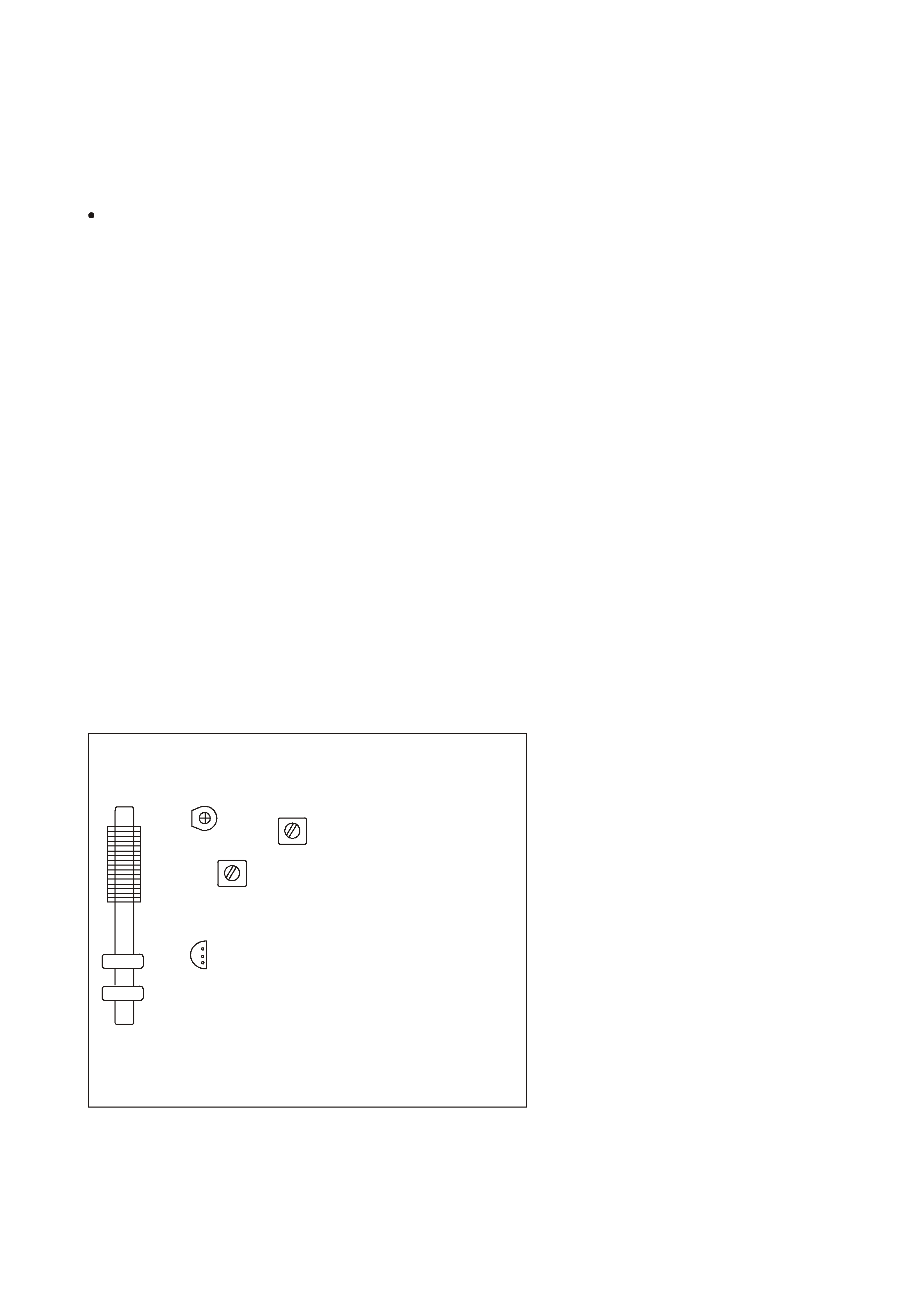
PC board shown are viewed from parts side.
The parts with no reference number or no parts number
in the exploded views are not supplied.
As regards the resistors and capacitors, refer to the
circuit diagrams contained in this manual.
Parts marked with this sign are safety critical
components. they must be replaced with identical
ensure exact replacement.
!
components - refer to the appropriate parts list and
1 SPECIFICATIONS
2
4 EXPLODED VIEW AND PARTS LIST
5 PC BOARDS AND PARTS LISTS
6 WIRING DIAGRAM
7 INCLUDED ACCESSORIES
2 SAFETY INFORMATION
3
7
12
20
22
3 ADJUSTMENT AND CHECKS
4
SR-L35
[T/C]: UL/CSA [E]: EUROPE [UK]: U.K.
CD RECEIVER
WALL-MOUNTABLE
1 SAFETY INFORMATION
2
SR-L35
USE OF CONTROLS OR ADJUSTMENT OR PERFORMANCE OF PROCEDURES OTHER THAN THOSE SPECIFIED HEREIN MAY
HAZARDOUS RADIATION EXPOSURE.
RESULT IN
SAFETY INFORMATION
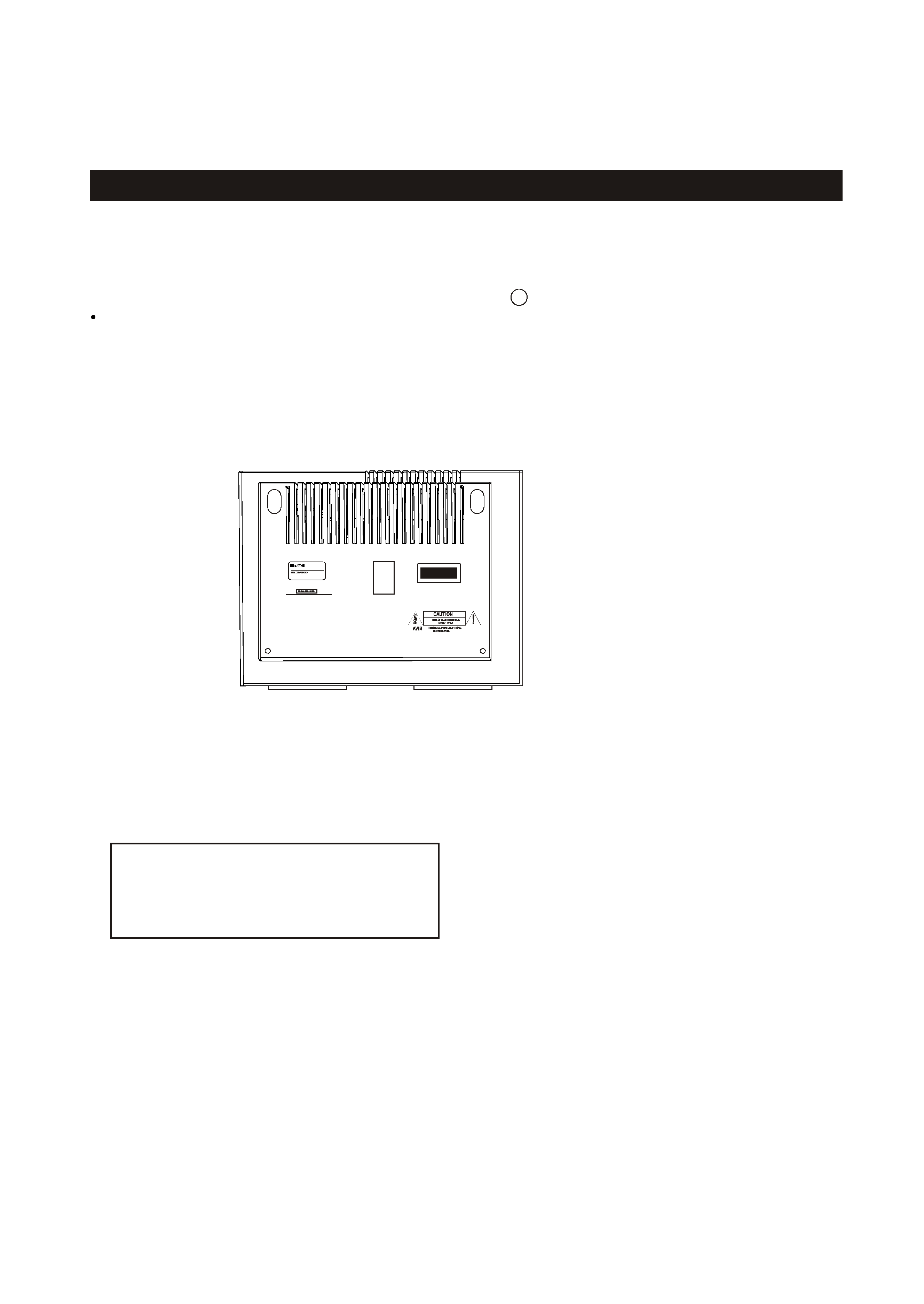
This product has been designed and manufactured according to FDA regulations " title 21, CFR, chapter 1,subchapter J,based on
The Radiation Control for Health and Safety Act of 1968" and is classified as class 1 laser product. There is not hazardous
invisible laser radiation during operation because invisible laser radiation emitted inside of this product is completely confined
in the protective housings. The label required in this regulation is shown
.
1
CAUTION
DO NOT REMOVE THE PROTECTIVE HOUSING USING SCREWDRIVER.
IF THIS PRODUCT DEVELOPS TROUBLE, MAKE A CONTACT WITH OUR SERICEMAN, AND DO NOT USE THE PRODUCT A TROUBLED
STATE.
Optical pickup:
Type
: CMS-M95BG6
Laser output : Less than 0.5 mW on the objective lens
Wavelength : 760 -800 nm
Manufacturer : Samsung Electro-Mechanic
CD RECEIVER
MODEL NO.SR-L35
DC12V
TOKYO JAPAN
CLASS 1 LASER PDODUCT
LUOKAN 1 LASERLAITE
KLASS 1 LASERAPPARAT

2 SPECIFICATIONS
SR-L35
3
Design and specifications are subject to change without notice.
Illustrations may differ slightly from production models.
Power Requirements:
GENERAL
Type :
Impedance :
65 mm x 2
4 ohms
SPEAKER SYSTEM Section
120V , 60Hz ( via dedicated AC adaptor) - USA
CD PLAYER Section
Frequency response :
20 Hz ~ 20 kHz
Wow and Flutter:
Unmeasurable
Total Output Power:
3W + 3W
Dimension (W x H x D ):
Weight: (net)
Standard Accessories:
Warranty Card x 1
6.4 lbs (2.9 kg)
Power Consumption:
AC Adaptor x 1
,
Template for Wall Mounting x 1
20 W
390 x 208 x 118 mm
Remote Control Unit (RC-969) x1
FM Lead-type Antenna x 1
Owner s Manual x 1
15.4 x 8.2 x 4.6 (inches)
230V , 50Hz (via dedicated AC adaptor) - EUR
240V , 50Hz ( via dedicated AC adaptor) - UK
TUNER Section
Frequency Range (FM):
87.5MHz to 108.00 MHz (100kHz step) - USA
Frequency Range (AM):
520kHz to 1710 kHz (10kHz step) - USA
522kHz to 1620 kHz (9kHz step) - EUR
87.5MHz to 108.00 MHz (50kHz step) - EUR
SR-L35
4
3 ADJUSTMENTS AND CHECKS
Use a screwdriver with a plastic or ceramic grip for all adjustment.
3-1 TUNER SECTION
1. Set the function switch to the TUNER position.
3-1-1 FM adjustment
3. Connect the signal generator output through a 75 ohm dummy
4. Connect the oscilloscope to the PHONES JACK terminal.
5. Connect the digital multimeter to Q16(C) on MAIN PCB.
antenna to "ANT" on MAIN PCB.
1. Set the function switch to the TUNER position.
3. Connect the test loop antenna across the output of the signal generator.
4. Connect the oscilloscope to the PHONES JACK terminal.
6. Set the signal generator as listed in the alignment chart.
3-1-2 AM adjustment
3-2 Adjustment and Test Points
MAIN PCB
TC1
L2
L3
L
1
A
M
A
N
T
C
O
IL
2. Set the BAND switch to the AM position.
2. Set the BAND switch to the FM position.
6. Set the signal generator as listed in the alignment chart.
5. Connect the digital multimeter to Q16(C) on MAIN PCB.
Q16
5
SR-L35
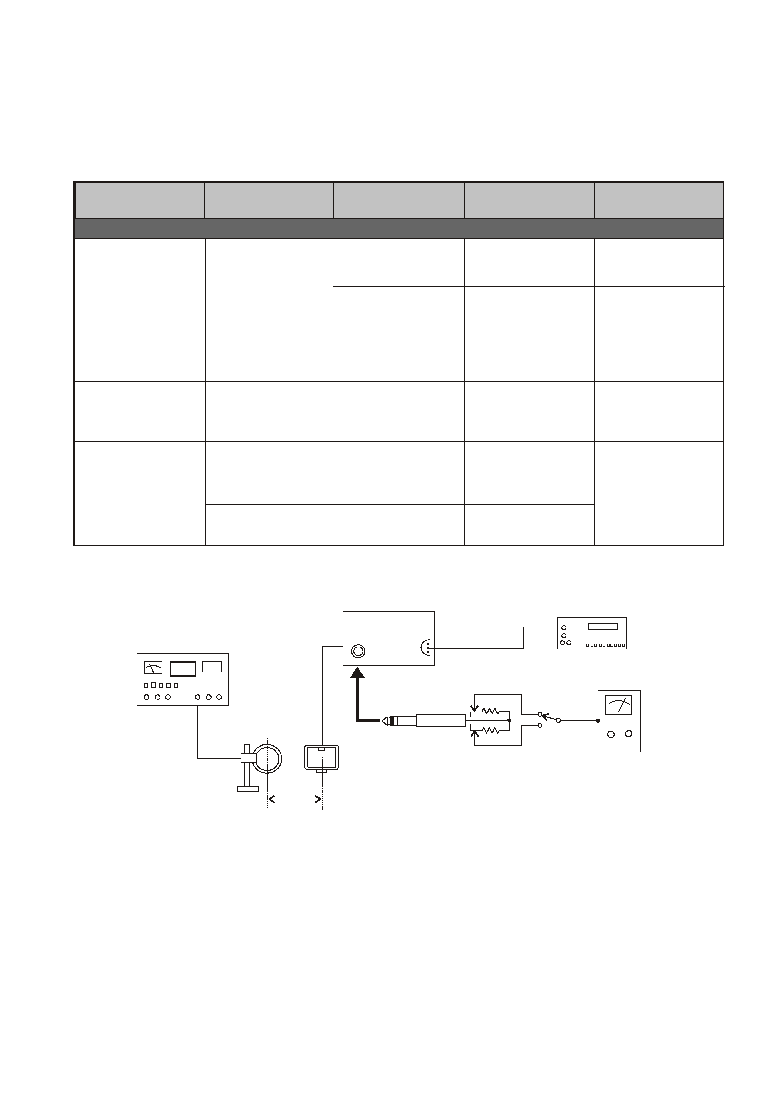
3-2-1 AM Tuner
60 cm
AM Loop
AM Signal Generator
Antenna
PHONES
SR-L35
Fig. 3-2-2
AM
ITEM
ADJUSTMENT
SG SETTING
TUNER SETTING
AM
2. IFT
450kHz
600kHz (USA)
1kHz, 30% mod
L3
Adjust for max.output.
3. ANT COIL
Repeat step 3
600kHz
1400kHz
1kHz, 30% mod
1kHz, 30% mod
L1
TC1
Adjust for max. output.
Adjust for max. output
and best waveform.
AM ant coil
600kHz (USA)
603kHz (EUR)
1400kHz (USA)
1404kHz (EUR)
603kHz (EUR)
1. VOLTAGE
adjustment
1710kHz (USA)
1620kHz (EUR)
L2
Check
VT
8.0V
VT
1.5V
522kHz (EUR)
520kHz (USA)
adjustment
4. TC1
adjustment
adjustment
repeat step 3
and 4
Digital multimeter
Q16
MEASURING POINTS.
RESULT
VT voltage
1 k ohm
1 k ohm
AC Voltmeter
S1