LT-1/LT-1B
1 SAFETY INFORMATION
PC board shown are viewed from parts side.
The parts with no reference number or no parts number
in the exploded views are not supplied.
As regards the resistors and capacitors, refer to the
circuit diagrams contained in this manual.
Parts marked with this sign are safety critical
components. they must be replaced with identical
ensure exact replacement.
!
components - refer to the appropriate parts list and
2 SPECIFICATIONS
4 EXPLODED VIEW AND PARTS LIST
5 PC BOARDS AND PARTS LISTS
6 WIRING DIAGRAM
7 INCLUDED ACCESSORIES
2
3
7
12
22
24
3 ADJUSTMENT AND CHECKS
4
WITH REMOTE CONTROL
Parts of [ ] mark can be used only with the version designated.
[T/C]: UL/CSA (LT-1) [EX/T]: UNI (LT-1)
CD / RADIO
[EUR]: VDE (LT-1B)
1 SAFETY INFORMATION
2
LT-1/LT-1B
USE OF CONTROLS OR ADJUSTMENT OR PERFORMANCE OF PROCEDURES OTHER THAN THOSE SPECIFIED HEREIN MAY
HAZARDOUS RADIATION EXPOSURE.
RESULT IN
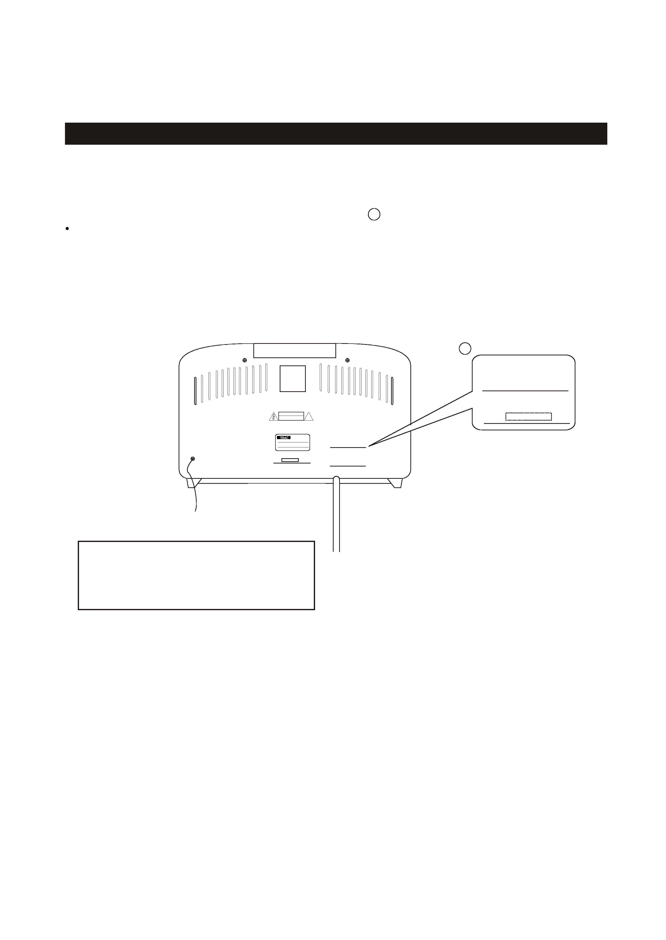
SAFETY INFORMATION
This product has been designed and manufactured according to FDA regulations " title 21, CFR, chapter 1,subchapter J,based on
The Radiation Control for Health and Safety Act of 1968" and is classified as class 1 laser product. There is not hazardous
invisible laser radiation during operation because invisible laser radiation emitted inside of this product is completely confined
in the protective housings. The label required in this regulation is shown
.
1
CAUTION
DO NOT REMOVE THE PROTECTIVE HOUSING USING SCREWDRIVER.
IF THIS PRODUCT DEVELOPS TROUBLE, MAKE A CONTACT WITH OUR SERICEMAN, AND DO NOT USE THE PRODUCT A TROUBLED
1
CERTIFICATION
THIS PRODUCT COMPLIES WITH DHHS
RULES 21 CFR SUBCHAPTER J APPLI-
CABLE AT DATE OF MANUFACTURE.
TEAC CORPORATION
3-7-3, NAKA-CHO, MUSASHINO-SHI, TOKYO, JAPAN
MANUFACTURED :
LTC
SERIAL
NO.
FOR U.S.A.
Optical pickup:
Type
: KSM-213CDM
Laser output : Less than 0.5 mW on the objective lens
Wavelength : 770 -795 nm
Manufacturer : SONY Corporation
STATE.
CERTIFICATION
THIS PRODUCT COMPLIES WITH DHHS
RULES 21 CFR SUBCHAPTER J APPLI-
CABLE AT DATE OF MANUFACTURE.
TEAC CORPORATION
3-7-3, NAKA-CHO, MUSASHINO-SHI, TOKYO, JAPAN
MANUFACTURED :
LTC
THIS CLASS B DIGITAL APPARATUS COMPLIES WITH
CANADIAN ICES-003.
CET APPAREIL NUMERIQUE DE LA CLASS B.
EST CONFORM A LA NORME NMB-003 DU CANADA.
THIS DEVICE COMPLIES WITH PART 15 OF THE
FCC RULES. OPERATION IS SUBJECT TO THE
FOLLOWING TWO CONDITIONS:(1) THIS DEVICE
MAY NOT CAUSE HARMFUL INTERFERENCE,AND
(2) THIS DEVICE MUST ACCEPT ANY INTERFER-
ENCE RECEIVED, INCLUDING INTERFERENCE
THAT MAY CAUSE UNDESIRED OPERATION.
SERIAL NO. LABEL
MODEL NO . LT-1
CD RADIO WITH REMOTE CONTROL
TEAC CORPORATION
40W
120V
60Hz
MADE IN CHINA
!
CAUTION
DO NOT OPEN
NE PAS OUVRIR.
AVIS
RISK OF ELECTRIC SHOCK
: RISQUE DE CHOC ELECTRIQUE
FM ANT

2 SPECIFICATIONS
LT-1/LT-1B
TUNER Section
Frequency Range (FM):
87.5MHz to 108.00 MHz (100kHz step) - U.S.A
3
Power Requirements:
120V AC,60Hz (U.S.A/Canada Model)
CD PLAYER Section
Frequency Response:
20 Hz to 20 kHz (+/- 1dB)
Wow and Flutter:
Unmeasurable
SPEAKER SYSTEM Section
Type:
1-way
Impedance:
8 ohms (L & R)
GENERAL
120/230V AC,50-60Hz (General Export Model)
8 ohms (subwoofer)
Design and specifications are subject to change without notice.
Illustrations may differ slightly from production models.
Dimension (W x H x D ):
Weight:
Standard Accessories:
Warranty Card x 1
357 x 205 x 247.5 mm
5.8 kg (12-13/16 lb)
Power Consumption:
40 W
Owner s Manual x 1
,
(14-1/18 x 8-1/16 x 9-3/4) inches
Remote Control (RC-910) x 1
Total Output Power :
15 W
Frequency Range (AM):
520kHz to 1710 kHz (10kHz step) - U.S.A
522kHz to 1620 kHz (9kHz step) - EUR
87.5MHz to 108.00 MHz (50kHz step) - EUR
230V AC,50Hz (EUR)
4
LT-1/LT-1B
3 ADJUSTMENTS AND CHECKS
Use a screwdriver with a plastic or ceramic grip for all adjustment.
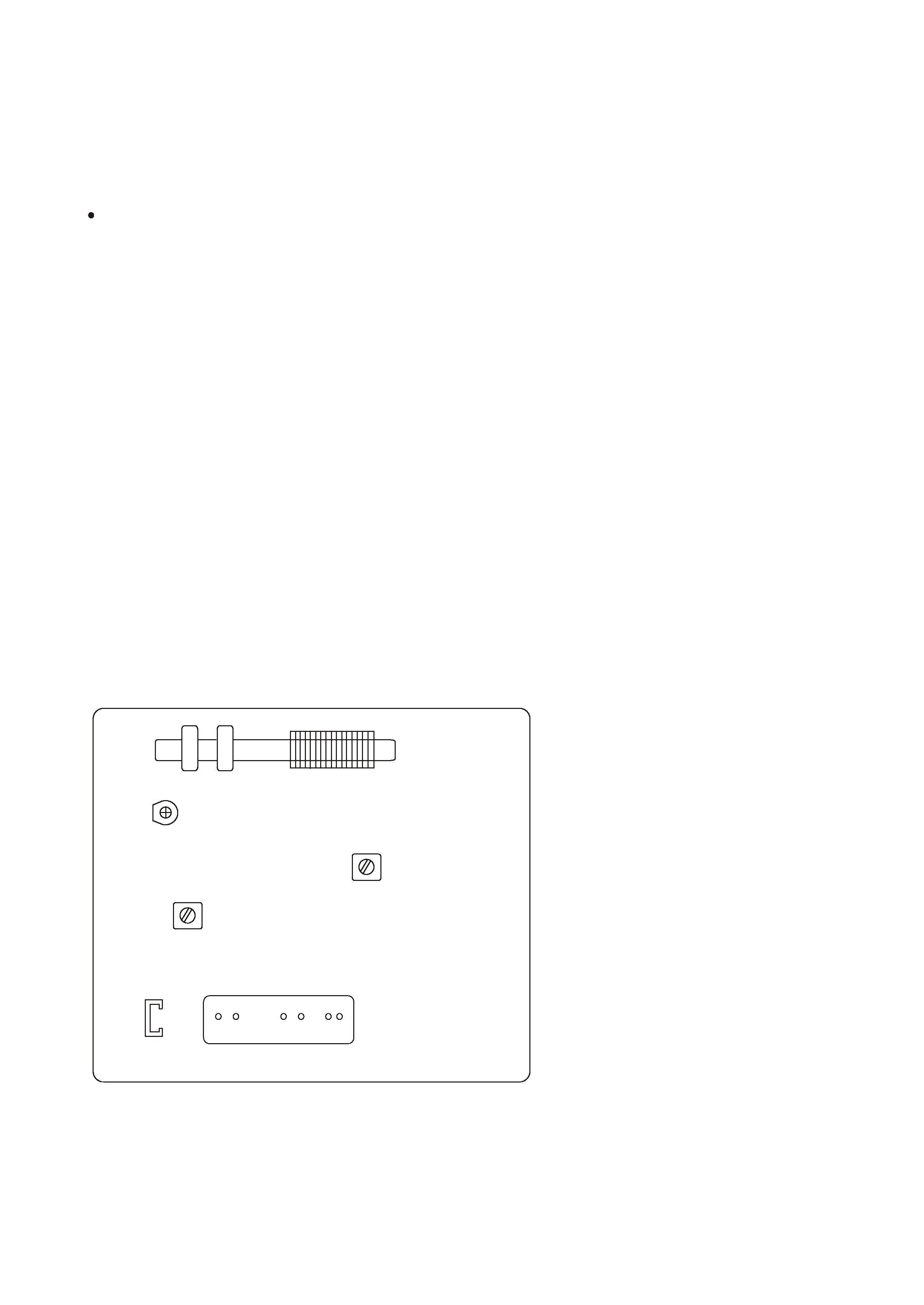
3-1 TUNER SECTION
L3
AM ANT COIL
L4
TC1
LT-1 TUNER PCB
L5
1. Set the function switch to the TUNER position.
3. Connect the signal generator output through a 75 ohm dummy
3. Connect the oscilloscope to the PHONE JACK terminal.
4. Set the signal generator as listed in the alignment chart.
3-1-2 FM adjustment
antenna to "ANT" on TUNER PCB.CN8.
2. Set the BAND switch to the FM position.
CN8
TUNER
1. Set the function switch to the TUNER position.
2. Connect the test loop antenna across the output of the signal generator.
3. Connect the oscilloscope to the PHONE JACK terminal.
4. Set the signal generator as listed in the alignment chart.
3-1-1 AM adjustment
2. Set the BAND switch to the AM position.
3-2 Adjustment and Test Points
Fig. 3-2-1
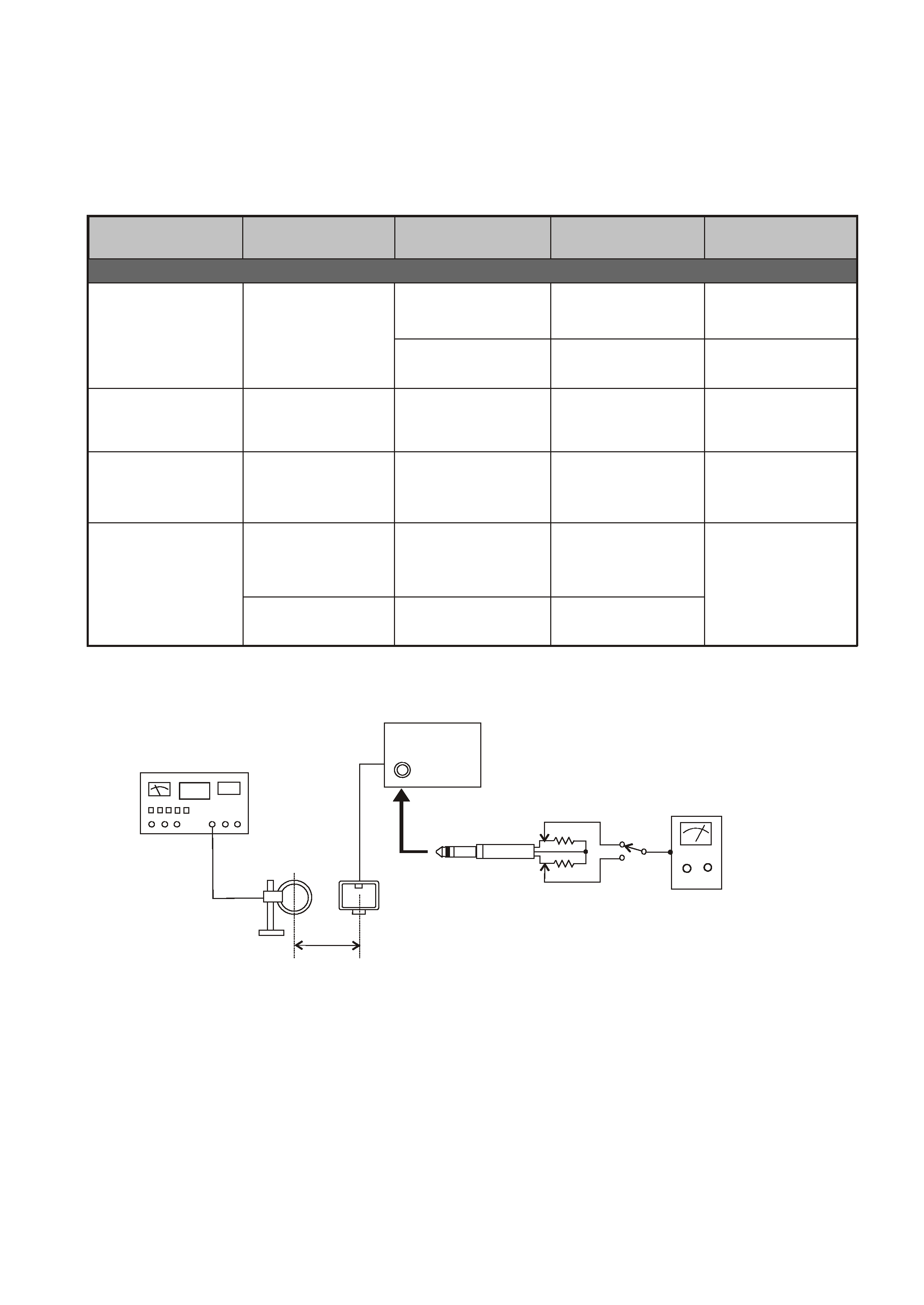
3-2-2 AM Tuner
LT-1/LT-1B
5
60 cm
AM Loop
AM Signal Generator
Antenna
PHONES
LT-1
Fig. 3-2-3
1 k ohm
1 k ohm
AC Voltmeter
AM
ITEM
ADJUSTMENT POINT
ADJUSTMENT
SG SETTING
TUNER SETTING
AM
2. IFT
450kHz
600kHz (USA)
1kHz, 30% mod
L5
Adjust for max.output.
3. ANT COIL
Repeat step 3
600kHz
1400kHz
1kHz, 30% mod
1kHz, 30% mod
L3
TC1
Adjust for max. output.
Adjust for max. output
and best waveform.
AM ant coil
600kHz (USA)
603kHz (EUR)
1400kHz (USA)
1404kHz (EUR)
603kHz (EUR)
1. VOLTAGE
adjustment
1710kHz (USA)
1620kHz (EUR)
L4
Check
VT
8.0V
VT
1.5V
522kHz (EUR)
520kHz (USA)
adjustment
4. TC1
adjustment
adjustment
repeat srep 3
and 4