
1-2
SECTION 1
SUMMARY
CONTENTS
PRODUCT SAFETY SERVICING GUIDELINES FOR VIDEO PRODUCTS ............................................. 1-3
SERVICING PRECAUTIONS ....................................................................................................................... 1-4
* General Servicing Precautions
* Insulation checking prodedure
* Electrostatically Sensitive Devices
SPECIFICATIONS ......................................................................................................................................... 1-5
LOCATION OF CUSTOMER CONTROLS ......................................................................................... 1-6 ~ 1-7
1-3
PRODUCT SAFETY SERVICING GUIDELINES FOR VIDEO PRODUCTS
CAUTION : DO NOT ATTEMPT TO MODIFY THIS PRODUCT IN
ANY WAY. NEVER PERFORM CUSTOMIZED INSTALLATIONS
WITHOUT MANUFACTURER'S APPROVAL. UNAUTHORIZED
MODIFICATIONS WILL NOT ONLY VOID THE WARRANTY, BUT
MAY LEAD TO YOUR BEING LIABLE FOR ANY RESULTING
PROPERTY DAMAGE OR USER INJURY.
SERVICE WORK SHOULD BE PERFORMED ONLY AFTER YOU
ARE THOROUGHLY FAMILIAR WITH ALL OF THE FOLLOWING
SAFETY CHECKS AND SERVICING GUIDELINES. TO DO
OTHERWISE, INCREASES THE RISK OF POTENTIAL HAZARDS
AND INJURY TO THE USER.
WHILE SERVICING, USE AN ISOLATION TRANSFORMER FOR
PROTECTION FROM A.C. LINE SHOCK.
SAFETY CHECKS
AFTER THE ORIGINAL SERVICE PROBLEM HAS BEEN
CORRCTED. A CHECK SHOULD BE MADE OF THE
FOLLOWING.
SUBJECT : FIRE & SHOCK HAZARD
1. BE SURE THAT ALL COMPONENTS ARE POSITIONED IN
SUCH A WAY AS TO AVOID POSSIBILITY OF ADJACENT
COMPONENT SHORTS. THIS IS ESPECIALLY IMPORTANT
ON THOSE MODULES WHICH ARE TRANSPORTED TO AND
FROM THE REPAIR SHOP.
2. NEVER RELEASE A REPAIR UNLESS ALL PROTECTIVE
DEVICES SUCH AS INSULATORS, BARRIERS, COVERS,
SHIELDS, STRAIN RELIEFS, POWER SUPPLY CORDS, AND
OTHER HARDWARE HAVE BEEN REINSTALLED PER
ORIGINAL DESIGN. BE SURE THAT THE SAFETY PURPOSE
OF THE POLARIZED LINE PLUG HAS NOT BEEN DEFEATED.
3. SOLDERING MUST BE INSPECTED TO DISCOVER POSSIBLE
COLD SOLDER JOINTS, SOLDER SPLASHES OR SHARP
SOLDER POINTS. BE CERTAIN TO REMOVE ALL LOOSE
FOREIGN PARTICLES.
4. CHECK FOR PHYSICAL EVIDENCE OF DAMAGE OR
DETERIORATION TO PARTS AND COMPONENTS. FOR
FRAYED LEADS, DAMAGED INSULATION (INCLUDING A.C.
CORD). AND REPLACE IF NECESSARY FOLLOW ORIGINAL
LAYOUT, LEAD LENGTH AND DRESS.
5. NO LEAD OR COMPONENT SHOULD TOUCH A RECIVING
TUBE OR A RESISTOR RATED AT 1 WATT OR MORE. LEAD
TENSION AROUND PROTRUNING METAL SURFACES MUST
BE AVOIDED.
6. ALL
CRITICAL
COMPONENTS
SUCH
AS
FUSES,
FLAMEPROOF RESISTORS, CAPACITORS, ETC. MUST BE
REPLACED WITH EXACT FACTORY TYPES, DO NOT USE
REPLACEMENT COMPONENTS OTHER THAN THOSE
SPECIFIED OR MAKE UNRECOMMENDED CIRCUIT
MODIFICATIONS.
7. AFTER RE-ASSEMBLY OF THE SET ALWAYS PERFORM AN
A.C.LEAKAGE TEST ON ALL EXPOSED METALLIC PARTS OF
THE CABINET, (THE CHANNEL SELECTOR KNOB, ANTENNA
TERMINALS. HANDLE AND SCREWS) TO BE SURE THE SET
IS SAFET TO OPERATE WITHOUT DANGER OF ELECTRICAL
SHOCK. DO NOT USE A LINE ISOLATION TRANSFORMER
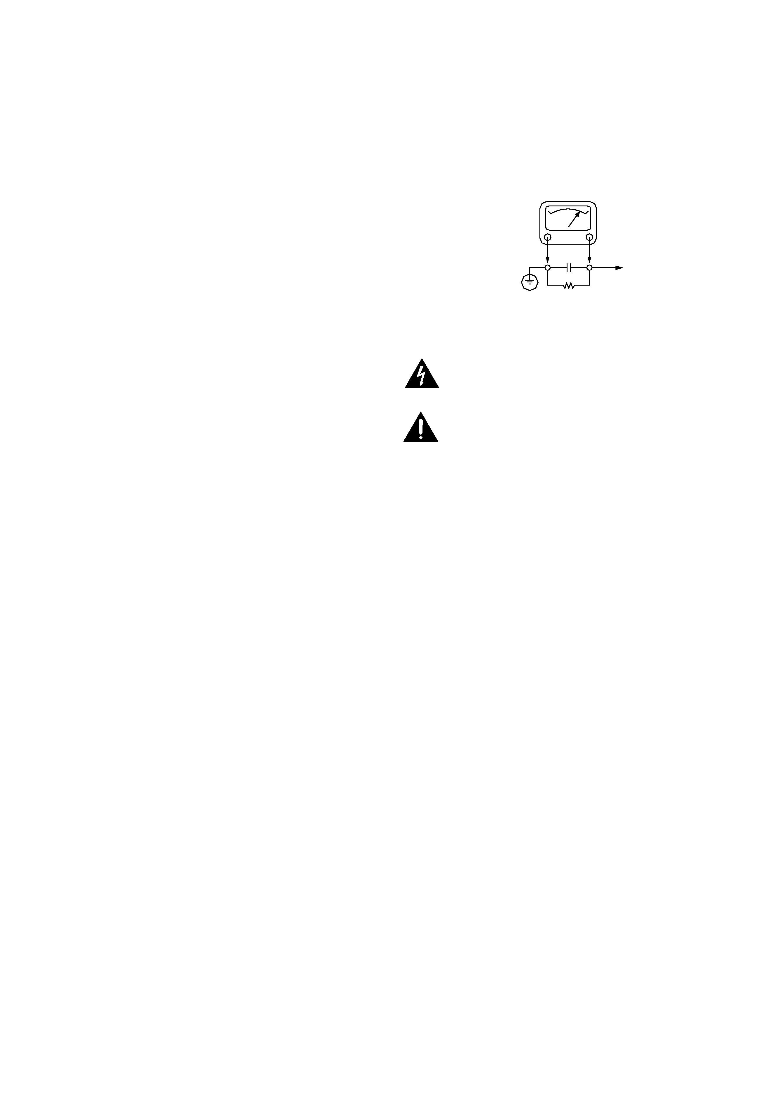
DURING THIS TEST USE AN A.C. VOLTMETER, HAVING 5000
OHMS PER VOLT OR MORE SENSITIVITY, IN THE
FOLLOWING MANNER; CONNECT A 1500 OHM 10 WATT
RESISTOR, PARALLELED BY A .15 MFD, 150.V A.C TYPE
CAPACITOR BETWEEN A KNOWN GOOD EARTH GROUND
(WATER PIPE, CONDUIT, ETC.) AND THE EXPOSED
METALLIC PARTS, ONE AT A TIME.
MEASURE THE A.C. VOLTAGE ACROSS THE COMBINATION
OF 1500 OHM RESISTOR AND .15 MFD CAPACITOR.
REVERSE THE A.C. PLUG AND REPEAT A.C. VOLTAGE
MEASUREMENTS FOR EACH EXPOSED METALLIC PART.
VOLTAGE MEASURE MUST NOT EXCEED 75 VOLTS R.M.S.
THIS CORRESPONDS TO 0.5 MILLIAMP A.C ANY VALUE
EXCEEDING THIS LIMIT CONSTITUTES A POTENTIAL
SHOCK HAZARD AND MUST BE CORRECTED IMMEDIATELY.
SUBJECT : GRAPHIC SYMBOLS
SUBJECT : TIPS ON PROPER INSTALLATION
1. NEVER INSTALL ANY PRODUCT IN A CLOSED-IN RECESS,
CUBBYHOLE OR CLOSELY FITTING SHELF SPACE. OVER
OR CLOSE TO HEAT DUCT, OR IN THE PATH OF HEATED
AIR FLOW.
2. AVOID CONDITIONS OF HIGH HUMIDITY SUCH AS:
OUTDOOR PATIO INSTALLATIONS WHERE DEW IS A
FACTOR, NEAR STEAM RADIATORS WHERE STEAM
LEAKAGE IS A FACTOR, ETC.
3. AVOID PALCEMENT WHERE DRAPERIES MAY OBSTRUCT
REAR VENTING. THE CUSTOMER SHOULD ALSO AVOID THE
USE OF DECORATIVE SCARVES OR OTHER COVERINGS
WHICH MIGHT OBSTRUCT VENTILATION.
4. WALL AND SHELF MOUNTED INSTALLATIONS USING A
COMMERCAL MOUNTING KIT. MUST FOLLOW THE
FACTORY APPROVED MOUNTING INSTRUCTIONS A
PRODUCT MOUNTED TO A SHELF OR PLATFORM MUST
RETAIN ITS ORIGINAL FEET (OR THE EQUIVALENT
THICKNESS IN SPACERS) TO PROVIDE ADEQUATE AIR
FLOW ACROSS THE BOTTOM, BOLTS OR SCREWS USED
FOR FASTENERS MUST NOT TOUCH ANY PARTS OR
WIRING. PERFORM LEAKAGE TEST ON CUSTOMIZED
INSTALLATIONS.
5. CAUTION CUSTOMERS AGAINST THE MOUNTING OF A
PRODUCT ON SLOPING SHELF OR A TILTED POSITION,
UNLESS THE PRODUCT IS PROPERLY SECURED.
6. A PRODUCT ON A ROLL-ABOUT CART SHOULD BE STABLE
ON ITS MOUNTING TO THE CART. CAUTION THE
CUSTOMER ON THE HAZARDS OF TRYING TO ROLL A CART
WITH SMALL CASTERS ACROSS THRESHOLDS OR DEEP
PILE CARPETS.
7. CAUTION CUSTOMERS AGAINST THE USE OF A CART OR
STAND WHICH HAS NOT BEEN LISTED BY UNDERWRITERS
LABORATORIES, INC. FOR USE WITH THEIR SPECIFIC
MODEL OF TELEVISION RECEIVER OR GENERICALLY
APPROVED FOR USE WITH T.V.'S OF THE SAME OR
LARGER SCREEN SIZE.
8. CAUTION CUSTOMERS AGAINST THE USE OF EXTENSION
CORDS, EXPLAIN THAT A FOREST OF EXTENSIONS
SPROUTING FROM A SINGLE OUTLET CAN LEAD TO
DISASTROUS CONSEQUENCES TO HOME AND FAMILY.
THE LIGHTNING FLASH WITH ARROWHEAD SYMBOL, WITHIN AN
EQUILATERAL TRIANGLE, IS INTENDED TO ALERT THE USER TO THE
PRESENCE OF UNINSULATED "DANGEROUS VOLTAGE" WITHIN THE
PRODUCT'S ENCLOSURE THAT MAY BE OF SUFFICIENT MAGNITUDE TO
CONSTITUTE A RISK OF ELECTRIC SHOCK.
THE EXCLAMATION POINT WITHIN AN EQUILATERAL TRIANGLE IS
INTENDED TO ALERT THE USER TO THE PRESENCE OF IMPORTANT
OPERATING AND MAINTENANCE (SERVICING) INSTRUCTIONS IN THE
LITERATURE ACCOMPANYING THE APPLIANCE.
A.C. VOLTMETER
PLACE THIS PROBE
ON EACH EXPOSED
METAL PART
GOOD EARTH GROUND
SUCH AS THE WATER
PIPE. CONDUIT. ETC
10 WATT
0.15uF

1-4
SERVICING PRECAUTIONS
CAUTION : Before servicing the DVD player covered by this service
data and its supplements and addends, read and follow the SAFETY
PRECAUTIONS. NOTE : if unforeseen circumstances create conflict
between the following servicing precautions and any of the safety
precautions in this publications, always follow the safety precautions.
Remembers Safety First:
General Servicing Precautions
1. Always unplug the DVD player AC power cord from the AC power
source before:
(1) Removing or reinstalling any component, circuit board,
module, or any other assembly.
(2) Disconnection or reconnecting any internal electrical plug or
other electrical connection.
(3) Connecting a test substitute in parallel with an electrolytic
capacitor.
Caution : A wrong part substitution or incorrect polarity installation
of electrolytic capacitors may result in an explosion hazard.
2. Do not spray chemicals on or near this DVD player or any of its
assemblies.
3. Unless specified otherwise in this service data, clean electrical
contacts by applying an appropriate contact cleaning solution to
the contacts with a pipe cleaner, cottontipped swab, or
comparable soft applicator.
Unless specified otherwise in this service data, lubrication of
contacts is not required.
4. Do not defeat any plug/socket B+ voltage interlocks with whitch
instruments covered by this service manual might be equipped.
5. Do not apply AC power to this DVD player and/or any of its
electrical assemblies unless all solid-state device heat sinks are
cerrectly installed.
6. Always connect test instrument ground lead to the appropriate
ground before connection the test instrument positive lead. Always
remove the test instrument ground lead last.
Insulation Checking Procedure
Disconnect the attachment plug from the AC outlet and turn the
power on. Connect an insulation resistance meter(500V) to the
blades of the attachment plug. The insulation resistance between
each blade of the attachment plug and accessible conductive parts
(Note 1) should be more than 1M-ohm.
Note 1 : Accessible Conductive Parts including Metal panels, Input
terminals, Earphone jacks, etc.
Electrostatically Sensitive (ES) Devices
Some semiconductor (solid state) devices can be damaged easily by
static electricity. Such components commonly are called
Electrostatically Sensitive (ES) Devices. Examples of typical Es
devices are integrated circuits and some field effect transistors and
semiconductor chip components.
The following techniques should be used to help reduce the
incidence of component damage caused by static electricity.
1. Immediately before handling any semiconductor component or
semiconductorequipped assembly, drain off any electrostatic
charge on your body by touching a known earth ground.
Alternatively, obtain and wear a commercially available
discharging wrist strap device, which should be removed for
potential shock reasons prior to applying power to the unit under
test.
2. After removing an electrical assembly equipped with ES devices,
place the assembly on a conductive surface such as aluminum
foil, to prevent electrostatic charge buildup or exposure of the
assembly.
3. Use only a grounded-tip soldering iron to solder or unsolder ES
devices.
4. Use only an antistatic solder removal device. Some solder
removal devices not classified a "anti-static" can generate
electrical charges sufficient to damage ES devices.
5. Do not use freonpropelled chemicals. These can generate
electrical charge sufficient to damage ES devices.
6. Do not remove a replacement ES device from its protec tive
package until immediately before you are ready to install it. (Most
replacement ES devices are packaged with leads electrically
shorted together by conductive foam, aluminum foil, or
comparable conductive material).
7. lmmediately before removing the protective material from the
leads of a replacement ES device, touch the protective material to
the chassis or circuit assembly into which the device will be
installed.
Caution : Be sure no power is applied to the chassis or circuit, and
observe all other safety precautions.
8. Minimize bodily motions when handing unpackaged replacement
ES devices. (Normally harmless motion such as the brushing
together of your clothes fabric or the lifting of your foot from a
carpeted floor can generate static electricity sufficient to damage
an ES device.)

1-5
SPECIFICATIONS
DVD VIDEO PLAYER
Power supply .............................................................. AC 230 V, 50 Hz (EUR)/ 120 V, 60 Hz (US/CANADA)
Power consumption .................................................... 22 W
External dimensions (W x H x D) ................................ 285 x 131 x 292 mm
Weight (net) ................................................................ 3.9 kg
Signal system ............................................................. PAL (EUR)/NTSC (US/CANADA)
Laser ........................................................................... Semiconductor laser, wavelength 650 nm
Frequency range (digital audio) .................................. 2 Hz to 22 kHz
Signal-to-noise rating (digital audio) ........................... More than 105 dB (EIAJ)
Audio dynamic range (digital audio) ........................... More than 92 dB (EIAJ)
Harmonic distortion (digital audio) .............................. 0.008%
Wow and flutter ........................................................... Below measurable level (less than + 0.001% (W.PEAK)) (EIAJ)
Operating conditions ................................................... Temperature: 41°F to 95°F, Operation status: Horizontal
OUTPUTS
Video output ............................................................... 1.0 V (p-p), 75
, negative sync., RCA jack x 1
S-video output ............................................................ (Y) 1.0 V (p-p), 75
, negative sync., Mini DIN 4-pin x 1
(C) 0.286 V (p-p) 75
Audio output (digital audio) ......................................... 0.5 V (p-p), 75
, RCA jack x 1
Audio output (analog audio) ....................................... 2.0 Vrms (1 kHz, 0 dB), RCA jack x1