C
CR
R--H
H22220
0
SERVICE MANUAL
CD Receiver
Effective : October, 2004
S-0129A
NOTES
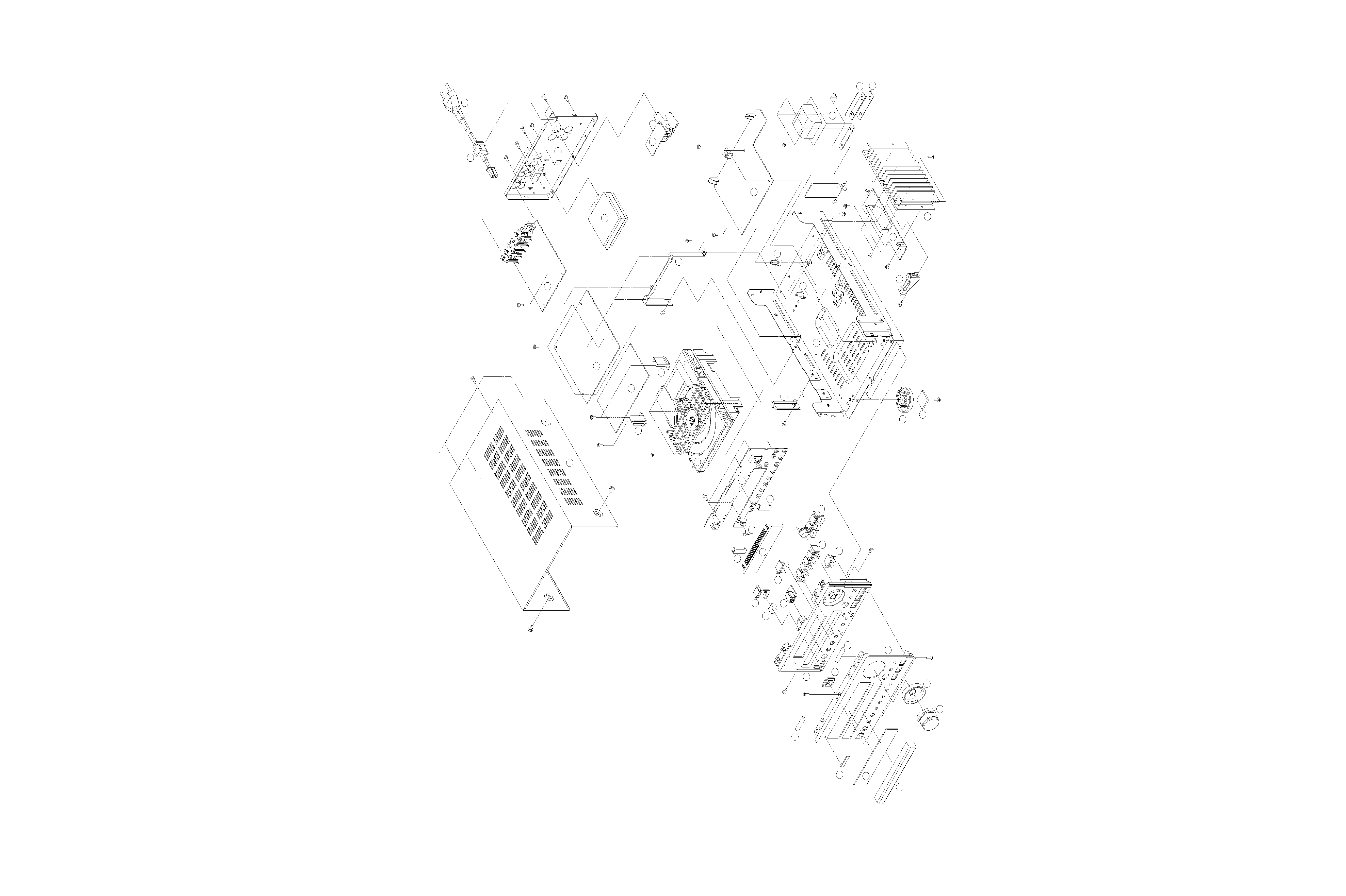
PC boards shown are viewed from parts side.
The parts with no reference number or no parts number in the
exploded views are not supplied.
As regards the resistors and capacitors, refer to the circuit diagrams
contained in this manual.
£
Parts marked with this sign are safety critical components. They
must be replaced with identical components - refer to the appropriate
parts list and ensure exact replacement.
Parts of [ ] mark can be used only with the version designated.
CONTENTS
1 SPECIFICATIONS
2
2 MICROCOMPUTER PIN FUNCTIONS
3
3 EXPLODED VIEWS AND PARTS LIST
5
4 PC BOARDS AND PARTS LIST
8
5 INCLUDED ACCESSORIES
12

1 SPECIFICATIONS
2
AMPLIFIER Section
Output Power .............................. 25 W/ch (6 ohms, 0.5 %,1 kHz)
Input Sensitivity ................................................ 300 mV/47k ohms
Frequency Response ...................... 20 Hz to 60,000 Hz (+1/-3 dB)
TUNER Section
FM Section
Frequency Range .......... 87.50 MHz to 108.00 MHz (50 kHz steps)
Signal-to-Noise Ratio .............................................. 65 dB (Mono)
60 dB (Stereo)
AM Section
Frequency Range .................... 522 kHz to 1629 kHz (9 kHz steps)
Signal-to-Noise Ratio............................................................ 35 dB
CD PLAYER Section
Frequency Response .......................... 20 Hz to 20,000 Hz (±2 dB)
Signal-to-Noise Ratio .......................................... more than 85 dB
Wow and Flutter ...................................................... Unmeasurable
GENERAL
Power Requirements............................................ 230 V AC, 50 Hz
Power Consumption .............................................................. 75 W
(standby) .............................................................................. 1.5 W
Dimension (W x H x D) ................................ 215 x 110 x 359 mm
Weight ................................................................................ 4.4 kg
Standard Accessories
Remote Control Unit (RC-959) x 1
Batteries (AA, R6, SUM-3) x 2
AM Loop Antenna x 1
FM Lead-type Antenna x 1
Owner's Manual x 1
Warranty Card x 1
· Design and specifications are subject to change without notice.
· Weight and dimensions are approximate.
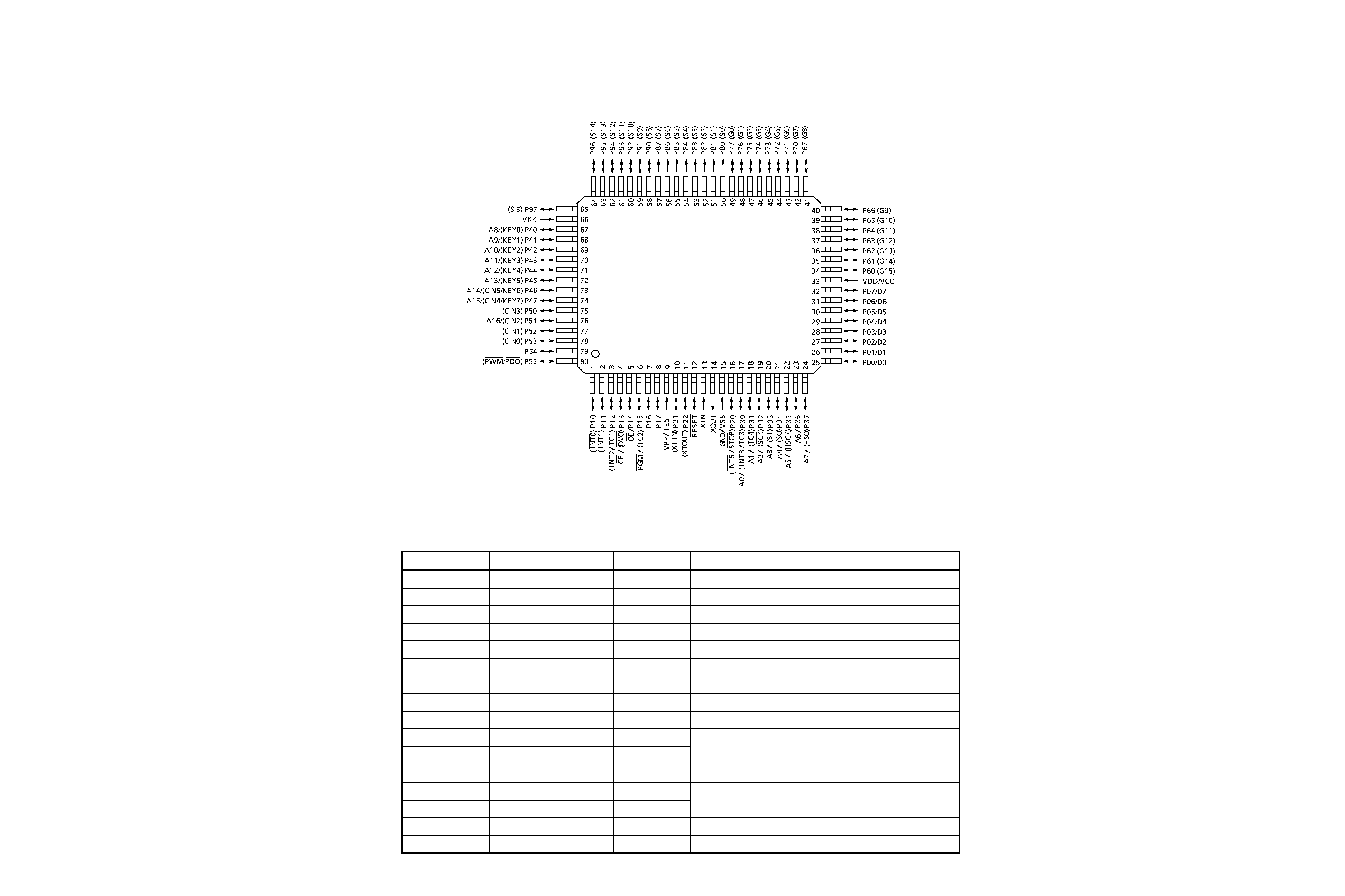
2 MICROCOMPUTER PIN FUNCTIONS
3
TMP87PS71AF
PIN No.
NAME
I/O
DESCRIPTION
1
F_MUTE
O
Function Mute Control port (Active "H")
2
REMOTE
I
Remote Data input port
3
RDS_CLK
I
RDS Clock input port
4
RDS_DATA
I
RDS Data input port
5
TAPE(H)
O
TAPE Control port (Active "H")
6
AUX2(H)
O
AUX2 Control port (Active "H")
7
N.C
-
No Connection
8
CD_STBY
O
CD_STANDBY On Control port
9
GND
-
GND
10
JOG2
I
11
JOG1
I
12
RESET
I
Reset port
13
X IN
-
14
X OUT
-
15
GND
-
GND
16
BACK_UP
I
BACKUP mode control port
JOG Data Input port(Master Volume)
8MHz Crystal Connection port

4
PIN No.
NAME
I/O
DESCRIPTION
17
CD_BUS0
I/O
18
CD_BUS1
I/O
19
CD_BUS2
I/O
20
CD_BUS3
I/O
21
CD_OPEN_SW
I
CD Open Switch input port
22
CD_CLOSE_SW
I
CD Close Switch input port
23
CD_LIMIT_SW
I
CD Limit Switch input port
24
TUNED_IN
I
Tuner Module Tuned port
25
STEREO_IN
I
Tuner Module Stereo port
26
N.C
-
No Connection
27
POWER_H
O
Power on port
28
PLL_DIN
I
PLL data input port
29
V-STB
O
Volume I.C(IC21) Chip enable port
30
P/V_CLK
O
PLL/VOLUME Colck output port
31
P/V_DATA
O
PLL/VOLUME Data output port
32
PLL_CE
O
PLL Chip enable port
33
VDD
I
Power Supply port
34~65
FIP_DATA
O
FIP Data output port
66
-30V
I
-30V Supply port
67
OPTION
I
option port
68
PROTECT
I
Protect Control port (Active "L")
69
H/P_IN
I
Headphone input control port
70
CD_POWER
O
CD Power control port
71
CD_RESET
O
CD Reset output port
72
CD_BUCK
O
CD DSP IC Clock port
73
CD_CCE
O
CD DSP IC Chip enable port (Active "L")
74
CD_RW
O
CD Control Interface
75
CD_OPEN_M
O
Open Motor control port
76
CD_CLOSE_M
O
Close Motor control port
77
KEY2
I
78
KEY1
I
79
SP_ON
O
Speaker On Control port
80
T_MUTE
O
Tuner Mute Control port
KEY Data input port
CD_BUS Interface port
5
3
1
2
4
5
6
7
8
9
10
11
11
12
13
17
14
15
15
16
17
18
19
19
20
21
22
23
24
24
25
26
27
28
29
30
31
32
33
34
35
36
37
38
39
40
41
42
42
3 EXPLODED VIEWS AND PARTS LIST