CCDD--PP66000000//CCDD--3300
SERVICE MANUAL
Compact Disc Player
Effective : March, 2000
D00551700A
CONTENTS
1 SPECIFICATIONS
2
2 ADJUSTMENT AND CHECKS
3
3 EXPLODED VIEWS AND PARTS LIST
6
4 PC BOARDS AND PARTS LIST
10
5 INCLUDED ACCESSORIES
13
6 BLOCK DIAGRAM
14

1 SPECIFICATIONS
2
CD-P6000/CD-30
CD-P6000
CD-30
CD-P6000
Pickup: ......................................................3 beam tracking system
Frequency Response: ....................................20Hz - 20kHz ±0.5dB
Harmonic Distortion: ........................................< 0.0015 % (1kHz)
Signal-to-Noise Ratio (S/N): ............................> 96dB (1kHz, 0dB)
Pitch Control: ........................................................................±12%
Wow and Flutter: ........................................Below measurable limit
Power Requirements:............................................230 V AC, 50 Hz
Power Consumption: ..............................................................12 W
Dimensions (W x H x D):................................435 x 101 x 301 mm
Weight (net): ........................................................................4.5 kg
Standard Accessories: ................Audio signal connection cord x 1
Wireless Remote Control Unit (RC-728)
Battery (UM-4, "AAA", "R03" type) x 2
Owner's Manual x 1
Warranty Card x 1
Improvements may result in specification or feature changes
without notice.
3
CD-P6000/CD-30
2 ADJUSTMENTS AND CHECKS
2-1 Replacement of the Pickup Assembly
2-1-1 Cautions in handling
Before servicing the pickup assembly be sure to prevent
electrostatic-inducer destruction by grounding not only test
equipment in use but also yourself.
*Electrostatic charge drastically shortens the operating life of
the laser diode or possibly results in its destruction.
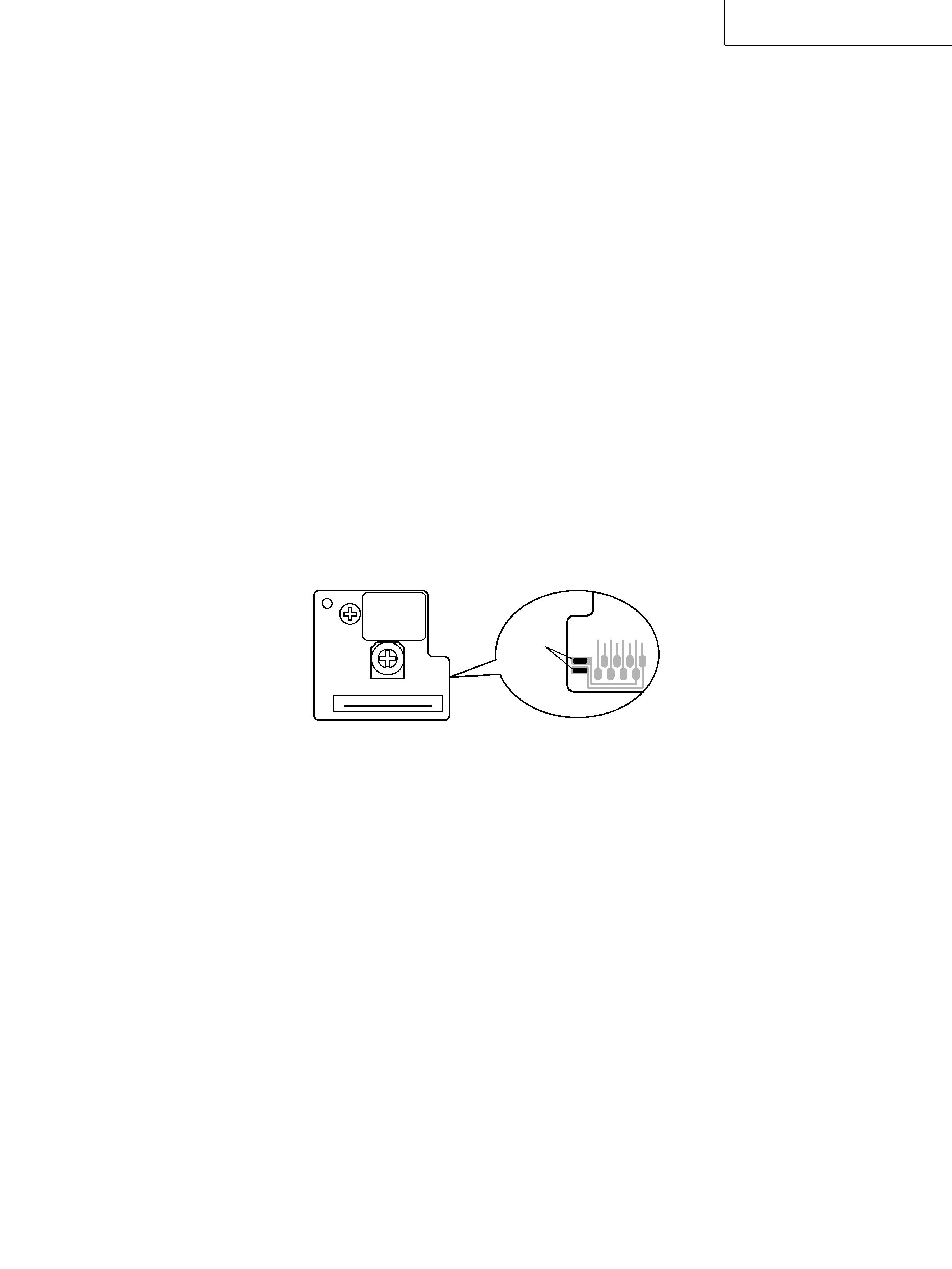
LD terminals are factory-strapped before shipment to protect
LD from electrostatic discharges during transportation. (Fig. 2-
1) After connector insertion, unstrap the LD terminal with a
soldering iron.
The temperature of the soldering iron tip must be 320
or
below (30W) and the unstrapping should be performed quickly.
Don't disassemble the pickup ass'y.
Don't apply shock to the pickup ass'y.
Don't place the assembly in a place subject to excessive dust,
heat or moisture.
The LD chip is manufactured from GaAs and GaAlAs, which
contains toxic As (Arsenic). Parts removed in servicing should
be disposed of with due care.
2-1-2 Objective
Never look directly into the LD or observe the laser beam
through another lens or mirror.
Don't touch the objective with fingers.
If objective becomes dirty, playback will deteriorate.
To clean the objective, moisten a good cleaning tissue, such as
made by KODAK, in isopropyl alcohol and wipe the objective
gently. Wipe off and excess fluid with a dry cleaning tissue.
KSS-213C
short land
pattern side
Fig. 2-1

4
CD-P6000/CD-30
2-2 Audio Check
2-2-1 Output level check
1. Connect the AC voltmeter to the LINE OUT.
2. Play the track 2 (1kHz, 0dB) of the MCD-111, and check the
output level.
Specification: 2.0
0.5Vrms (50k
load)
2-2-2 PHONES level check
1. Connect the AC voltmeter to the PHONES.
2. Play the track 2 (1kHz, 0dB) of the MCD-111, and check the
output level.
Specification: 1.0
0.3Vrms (PHONES VR: MAX, 32
load)
2-2-3 Distortion check
1. Connect the distortion meter to the LINE OUT.
2. Play the track 2 (1kHz, 0dB) of the MCD-111, and check the
distortion.
Specification: 0.01% or less (PITCH CONTROL OFF, 20kHz LPF IN)
0.03% or less (PITCH CONTROL ON, 20kHz LPF IN)
2-2-4 Frequency response check
1. Play the track 3-6 (20Hz 20kHz, 0dB) of the MCD-111, and
check that output level are within the specified values with
respect to the 1kHz reference level.
Specification: within
0.5dB
2-2-5 S/N check
1. Play the track 7 (non-signal) of the MCD-111, and check that
noise level are within the specified values with respect to the
1kHz reference level.
Specification: 96dB or more (A-WEIGHT)
2-2-6 Channel separation check
1. Play the track 8 (L:1kHz / R:non-signal) of the MCD-111, and
check the leakage from Lch to Rch.
2. In the same way, play the track 10 (R:1kHz / L:non-signal) of
the MCD-111, and check the leakage from Rch to Lch.
Specification: 85dB or more (A-WEIGHT)
2-2-7 Emphasis effect
1. Play the track 13 (16kHz) of the MCD-111, and check that
output level are within the specified values with respect to the
1kHz reference level.
Specification:
20
0.5dB

5
CD-P6000/CD-30
NOTES
PC boards shown are viewed from parts side.
Parts marked with * require longer delivery time.
The parts with no reference number or no parts number in the
exploded views are not supplied.
As regards the resistors and capacitors, refer to the circuit diagrams
contained in this manual.
£
Parts marked with this sign are safety critical components. They
must be replaced with identical components - refer to the appropriate
parts list and ensure exact replacement.
Parts of [ ] mark can be used only with the version designated.
£