ENGLISH
9A10448600
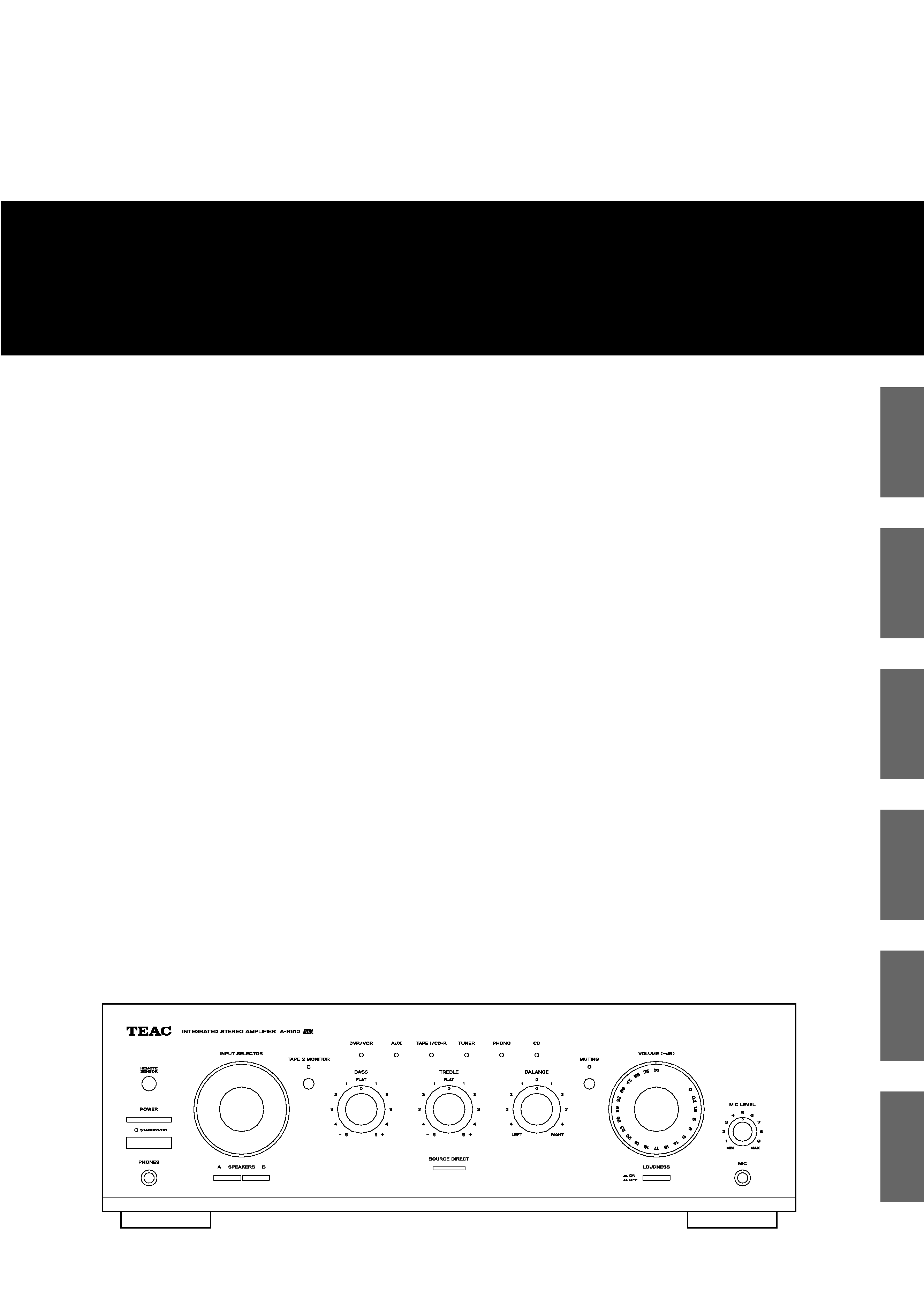
Integrated Stereo Amplifier
OWNER'S MANUAL
MANUEL DU PROPRIÉTAIRE
MANUAL DEL USUARIO
BEDIENUNGSANLEITUNG
MANUALE DI ISTRUZIONI
GEBRUIKSAANWIJZING
Z
A-R610
FRANÇAIS
ESPAÑOL
DEUTSCH
ITALIANO
NEDERLANDS
2
CAUTION
<
DO NOT REMOVE THE EXTERNAL CASES OR CABINETS TO
EXPOSE THE ELECTRONICS. NO USER SERVICEABLE PARTS
ARE WITHIN!
<
IF YOU ARE EXPERIENCING PROBLEMS WITH THIS PRODUCT,
CONTACT TEAC FOR A SERVICE REFERRAL. DO NOT USE THE
PRODUCT UNTIL IT HAS BEEN REPAIRED.
WARNING: TO PREVENT FIRE OR SHOCK
HAZARD, DO NOT EXPOSE THIS APPLIANCE
TO RAIN OR MOISTURE.
IMPORTANT SAFETY INSTRUCTIONS
1) Read these instructions.
2) Keep these instructions.
3) Heed all warnings.
4) Follow all instructions.
5) Do not use this apparatus near water.
6) Clean only with dry cloth.
7) Do not block any ventilation openings. Install in accordance
with the manufacturer's instructions.
8) Do not install near any heat sources such as radiators, heat
registers, stoves, or other apparatus (including amplifiers) that
produce heat.
9) Do not defeat the safety purpose of the polarized or
grounding-type plug. A polarized plug has two blades with
one wider than the other. A grounding type plug has two
blades and a third grounding prong. The wide blade or the
third prong are provided for your safety. If the provided plug
does not fit into your outlet, consult an electrician for
replacement of the obsolete outlet.
10) Protect the power cord from being walked on or pinched
particularly at plugs, convenience receptacles, and the point
where they exit from the apparatus.
11) Only use attachments/accessories specified by the
manufacturer.
12) Use only with the cart, stand, tripod,
bracket, or table specified by the
manufacturer, or sold with the apparatus.
When a cart is used, use caution when
moving the cart/apparatus combination to
avoid injury from tip-over.
13) Unplug this apparatus during lightning storms or when
unused for long periods of time.
14) Refer all servicing to qualified service personnel. Servicing is
required when the apparatus has been damaged in any way,
such as power-supply cord or plug is damaged, liquid has
been spilled or objects have fallen into the apparatus, the
apparatus has been exposed to rain or moisture, does not
operate normally, or has been dropped.
CAUTION: TO REDUCE THE RISK OF ELECTRIC SHOCK,
DO NOT REMOVE COVER (OR BACK). NO USER-
SERVICEABLE PARTS INSIDE. REFER SERVICING TO
QUALIFIED SERVICE PERSONNEL.
The lightning flash with arrowhead symbol, within an
equilateral triangle, is intended to alert the user to the
presence of uninsulated "dangerous voltage" within
the product's enclosure that may be of sufficient
magnitude to constitute a risk of electric shock to
persons.
The exclamation point within an equilateral triangle is
intended to alert the user to the presence of important
operating and maintenance (servicing) instructions in
the literature accompanying the appliance.
<
Do not expose this apparatus to drips or splashes.
<
Do not place any objects filled with liquids, such as vases, on
the apparatus.
<
Do not install this apparatus in a confined space such as a
book case or similar unit.
<
The apparatus draws nominal non-operating power from the
AC outlet with its POWER switch in the off position.
<
The apparatus should be located close enough to the AC
outlet so that you can easily grasp the power cord plug at
any time.
<
An apparatus with Class ! construction shall be connected to
an AC outlet with a protective grounding connection.
3
ENGLISH
Contents
Thank you for choosing TEAC. Read this manual carefully
to get the best performance from this unit.
Before Use . . . . . . . . . . . . . . . . . . . . . . . . . . . . . . . . . . . . . . . . 3
Connection. . . . . . . . . . . . . . . . . . . . . . . . . . . . . . . . . . . . . . . . 4
Names of Each Control . . . . . . . . . . . . . . . . . . . . . . . . . . . . . . . 6
Remote Control Unit. . . . . . . . . . . . . . . . . . . . . . . . . . . . . . . . . 8
Basic Operation. . . . . . . . . . . . . . . . . . . . . . . . . . . . . . . . . . . . . 8
TroubleShooting . . . . . . . . . . . . . . . . . . . . . . . . . . . . . . . . . . . 11
Specifications . . . . . . . . . . . . . . . . . . . . . . . . . . . . . . . . . . . . . 12
Before Use
CAUTION Regarding Placement
To maintain proper ventilation, be sure to leave a space
around the unit (from the largest outer dimensions including
projections) equal to, or greater than, shown below.
Left and Right Panels
: 10 cm
Rear Panel
: 10 cm
Top Panel
: 50 cm
Read this before operation
<
As the unit may become warm during operation, always leave
sufficient space around the unit for ventilation.
The ventilation holes should not be covered. Make sure there
is at least 50 cm (18 inches) of space above and at least 10
cm (4 inches) of space on each side of the unit. Do NOT place
anything on top of the unit.
<
The voltage supplied to the unit should match the voltage as
printed on the rear panel. If you are in any doubt regarding
this matter, consult an electrician.
<
Choose the installation location of your unit carefully. Avoid
placing it in direct sunlight or close to a source of heat. Also
avoid locations subject to vibrations and excessive dust, heat,
cold or moisture.
<
Do not place the unit on the amplifier/receiver.
<
Do not open the cabinet as this might result in damage to the
circuitry or electrical shock. If a foreign object should get into
the unit, contact your dealer or service company.
<
When removing the power plug from the wall outlet, always
pull directly on the plug, never yank the cord.
<
Do not attempt to clean the unit with chemical solvents as
this might damage the finish. Use a clean, dry or slightly
damp cloth.
<
Keep this manual in a safe place for future reference.
LINE
OUT
LINE
OUT
REMOTE
CONTROL
LINE
IN
RL
LR
RL
LINE
OUT
RL
C
B
A
A
E
F
D
4
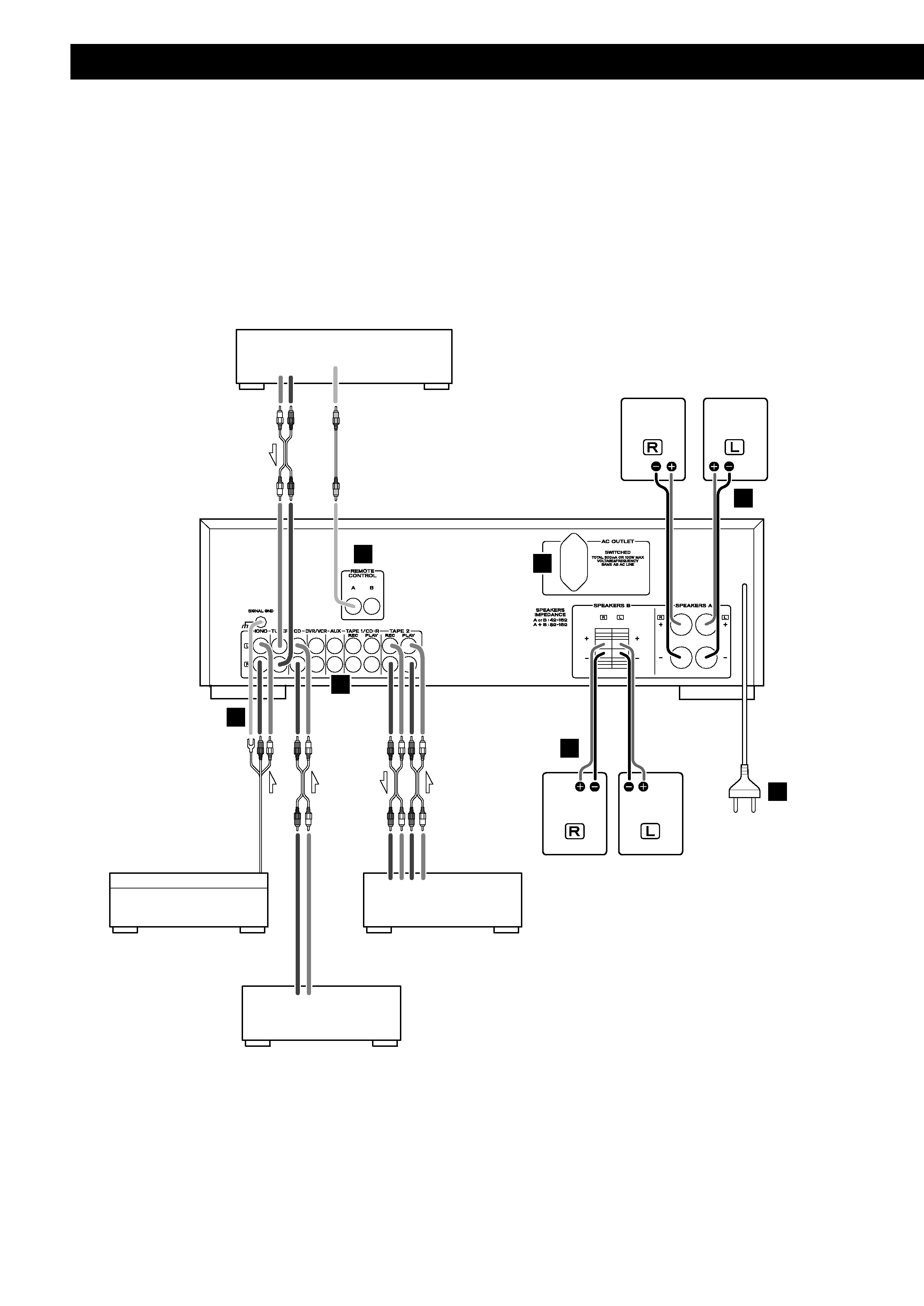
Connection
CAUTION:
<
Switch off the power to all equipment before making connections.
<
Read the instructions of each component you intend to use with this unit.
<
Be sure to insert each plug securely. To prevent hum and noise, avoid bundling the signal
interconnection cables together with the AC power cord or speaker cables.
TUNER (T-R610)
TURNTABLE
TAPE
Speakers A
Speakers B
CD/DVD player
PHONO q Turntable
TUNER q Tuner (T-R610)
CD q CD player
DVR/VCR q Video cassette recorder, etc.
AUX q Audio component
TAPE1/CD-R q Cassette tape deck, CD recorder, etc.
TAPE2 q Cassette tape deck, CD recorder, etc.
5
ENGLISH
AUDIO IN/OUT jacks
Analog 2-channel audio signal is input or output from these
jacks. Connect the component with commercially-available
RCA cables.
Make sure to connect:
white plug q white jack (L: left channel)
red plug q red jack (R: right channel)
PHONO jacks/SIGNAL GND terminal
Connect the turntable's RCA pin cords to PHONO jacks.
Make sure to connect:
white plug q white jack (L: left channel)
red plug q red jack (R: right channel)
Connect the turntable's ground cord to SIGNAL GND
terminal.
AC Outlet (switched)
This outlet is active only when the unit is on.
Caution:
Make sure that the total power consumption of all
equipment connected to the outlet does not exceed 500mA
or 100 watts.
REMOTE CONTROL jacks
If you have TEAC T-R610, connect the REMOTE CONTROL
jack (A or B) of each component by the remote control cord
(provided with the T-R610).
Power cord (AC)
Be sure to connect the power cord to an AC outlet which
supplies the correct voltage.
Hold the power plug when plugging or unplugging the
power cord. Never pull or yank on the power cord.
F
E
D
C
B
Speaker Connections
Caution:
To avoid damaging the speakers with a sudden high-level
signal, be sure to switch the power off before connecting
the speakers.
<
Check the impedance of your speakers. Connect speaker
with an impedance of 4 to 16 ohms when using only one
pair of speakers (SPEAKERS A or SPEAKERS B). When using
two pairs of speakers simultaneously, the impedance should
be 8 to 16 ohms.
<
The black speaker terminals are _ (negative).
Generally, the + side of the speaker cable is marked to
make it distinguishable from the _ side of the cable.
Connect this marked side to the + terminal and the
unmarked side to the black _ terminal.
<
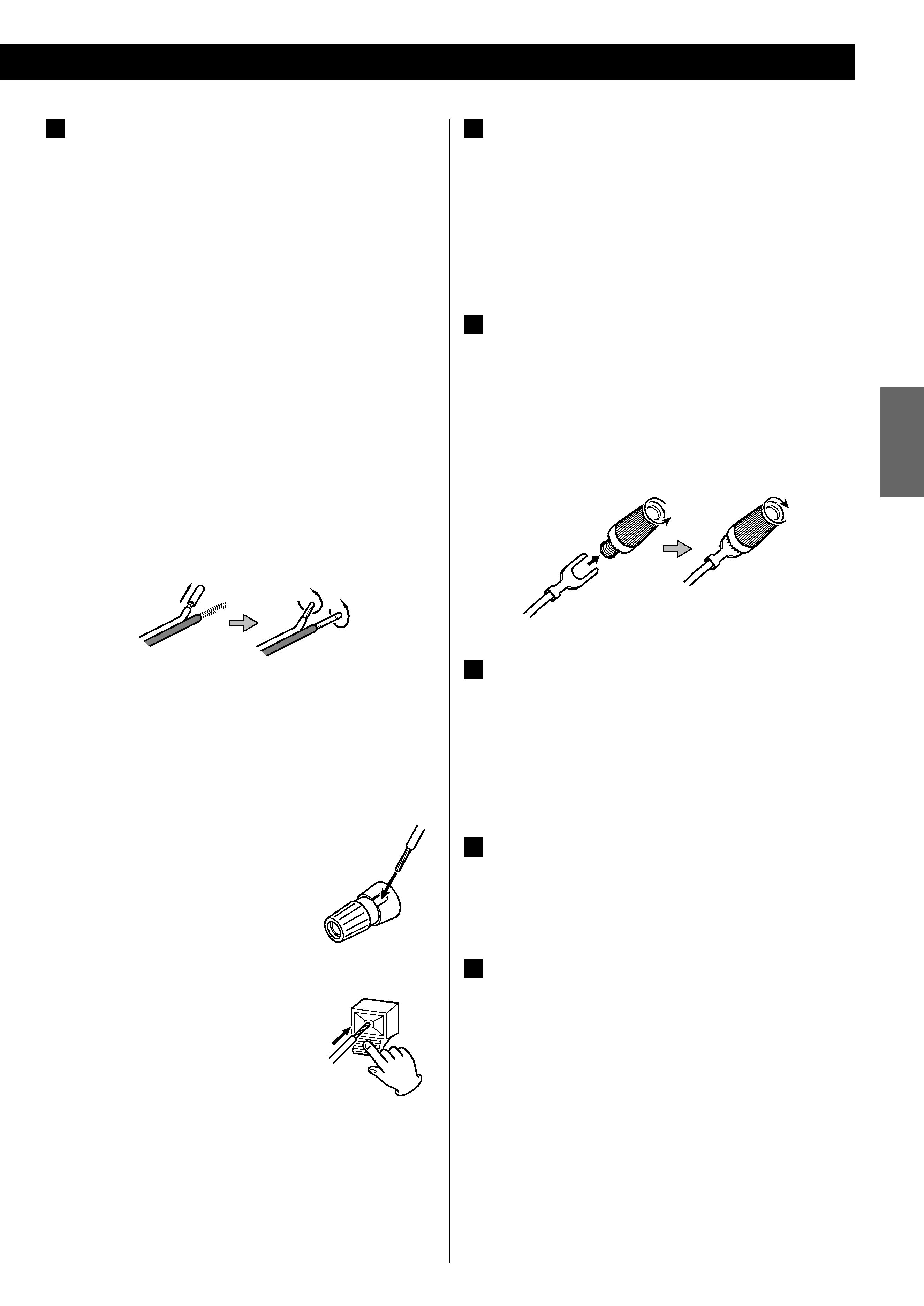
Prepare the speaker cables for connection by stripping off
approximately 10 mm or less of the outer insulation.
(Removing too much insulation may lead to a short circuit if
the bared wires should come in contact with each other.)
Twist the strands of the stripped wires tightly together:
Caution:
The metal portions of the two separate wires should not
touch or an electrical short can occur. Shorted wires can
create a fire hazard or induce a failure in your equipment.
How to connect
Speakers A
1. Turn the terminal cap counterclockwise
to loosen it. The speaker terminal caps
cannot be fully removed from the base.
2. Insert the wire into the terminal fully and
turn the terminal cap clockwise to
securely connect it .
Speakers B
Press the lever, insert the wire, then
release the lever.
<
Make sure none of the wire insulation is under the terminal,
only the bare, stripped wire.
<
Make sure the wire is fastened firmly by pulling the cable
lightly.
A