A
AG
G--3
3770
0
SERVICE MANUAL
AM/FM Stereo Receiver
Effective : April, 2003
S-0091A
NOTES
PC boards shown are viewed from parts side.
The parts with no reference number or no parts number in the
exploded views are not supplied.
As regards the resistors and capacitors, refer to the circuit diagrams
contained in this manual.
£
Parts marked with this sign are safety critical components. They
must be replaced with identical components - refer to the appropriate
parts list and ensure exact replacement.
CONTENTS
1 SPECIFICATIONS
2
2 ADJUSTMENTS AND CHECKS
3
3 EXPLODED VIEWS AND PARTS LIST
6
4 PC BOARDS AND PARTS LIST
8
1 SPECIFICATIONS
2
Amplifier Section
Output Power .... 50 + 50 watts RMS (0.9 % THD, 1 kHz, 8 ohms)
Total Harmonic Distortion.................... 0.05 % (at 45 watts,1 kHz)
Input Sensitivity/Impedance .................. PHONO: 4 mV/22 kohms
LINE: 270 mV/20 kohms
Frequency Response.................... PHONO: 20 Hz20 kHz, +/3 dB
LINE: 20 Hz30 kHz, +1/3 dB
Signal-to-Noise Ratio.............................................. PHONO: 60 dB
LINE: 68 dB
Tone Control .......................................... BASS: +/9 dB at 100 Hz
TREBLE: +/7 dB at 10 kHz
Loudness Control (Volume at 40 dB Position) ..............................
+7 dB at 100 Hz, +5 dB at 10 kHz
FM Tuner Section
(Without notes 98.1 MHz, 65 dBf)
Tuning Range .................... 87.5 MHz108.0 MHz (100 kHz steps)
Usable Sensitivity (IHF) ............................................ Mono: 20 dBf
50 dB Quieting Sensitivity ................ Mono: 39 dBf, Stereo: 46 dBf
Capture Ratio ...................................................................... 2.8 dB
Image Rejection Ratio .......................................................... 20 dB
AM Suppresion Ratio............................................................ 48 dB
Harmonic Distortion (1 kHz) .............. Mono: 0.4 %, Stereo: 0.5 %
Frequency Response................................ 30 Hz15 kHz, +2/3 dB
Stereo Separation (1 kHz) .................................................... 35 dB
Signal-to-Noise Ratio ........................ Mono: 57 dB, Stereo: 55 dB
AM Tuner Section
Tuning Range .......................... 520 kHz1,720 kHz (10 kHz steps)
Usable Sensitivity ............................................................ 55 dB/m
Total Harmonic Distortion .................................... 1 % at 85 dB/m
Signal-to-Noise Ratio............................................................ 48 dB
General
Power Requirements.................................. 120 V/230 V, 50-60 Hz
Power Consumption ............................................................ 120 W
AC Outlet .......................... Unswitched x 1, 100 W max (1 A max)
Dimensions (W x H x D) ........................ 17-1/8" x 5-1/8" x 12-5/8"
(435 x 130 x 320 mm)
Weight (net) .................................................. 15-7/16 lbs (7.0 kg)
Standard Accessories .................................. AM Loop Antenna x 1
FM "T" Type Antenna x 1
· Design and specifications are subject to change without notice.
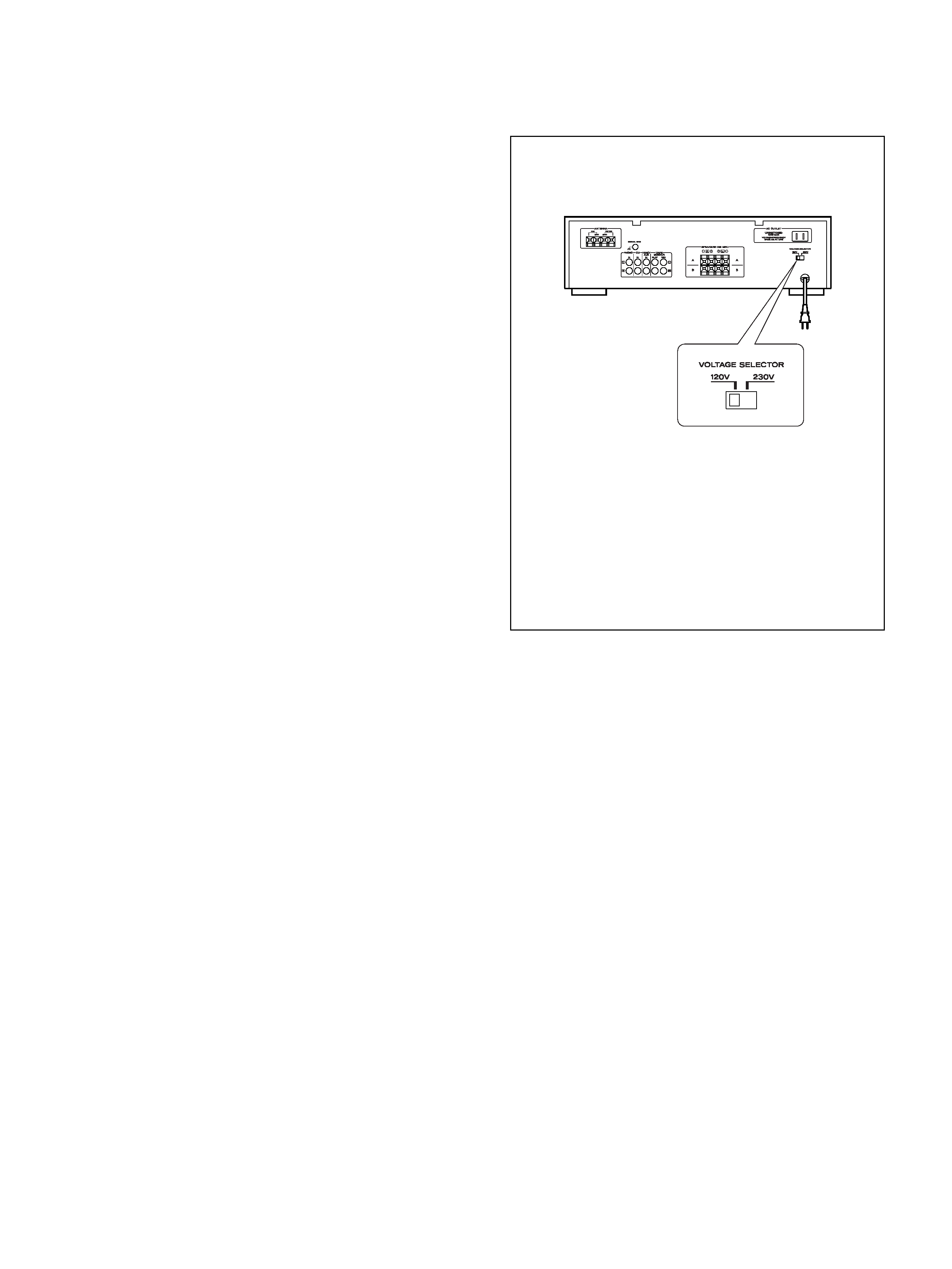
Voltage Conversion
(General export models only)
Be sure to remove the power cord from the AC outlet before
repositioning the voltage converter switch.
1. Locate the voltage selector on the rear panel.
2. Using a flat-bladed screwdriver, set to the appropriate
230V or 120V position according to your area.
IN NORTH AMERICA USE ONLY ON 120 V SUPPLY.
2 ADJUSTMENTS AND CHECKS
3
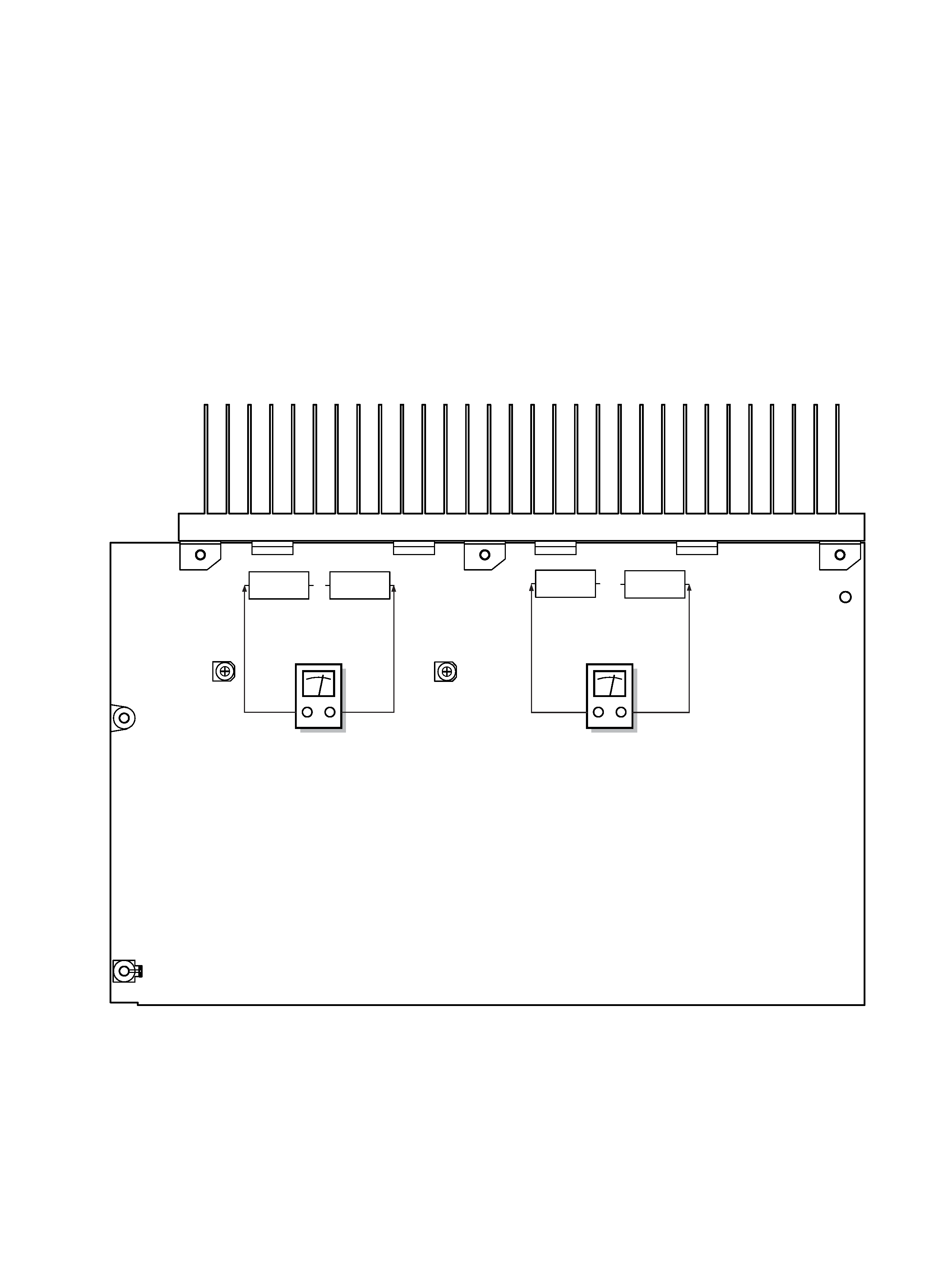
2-1 AMPLIFIER SECTION
Bias Current Adjustment
1. Turn the unit on, and set the input selector switch to "CD".
2. Set 7VR1 and 7VR2 to the center position.
3. Connect the DC voltmeter as shown below after preheating for
10 minutes, and adjust 7VR1 (Lch) so that the voltage
becomes 3.3 1.3mV.
4. Adjust 7VR2 (Rch) in the same way.
7VR1
7VR2
7R46
7R44
7R45
7R43
0.33/5W
0.33/5W
0.33/5W
0.33/5W
MAIN PCB
DC voltmeter
DC voltmeter
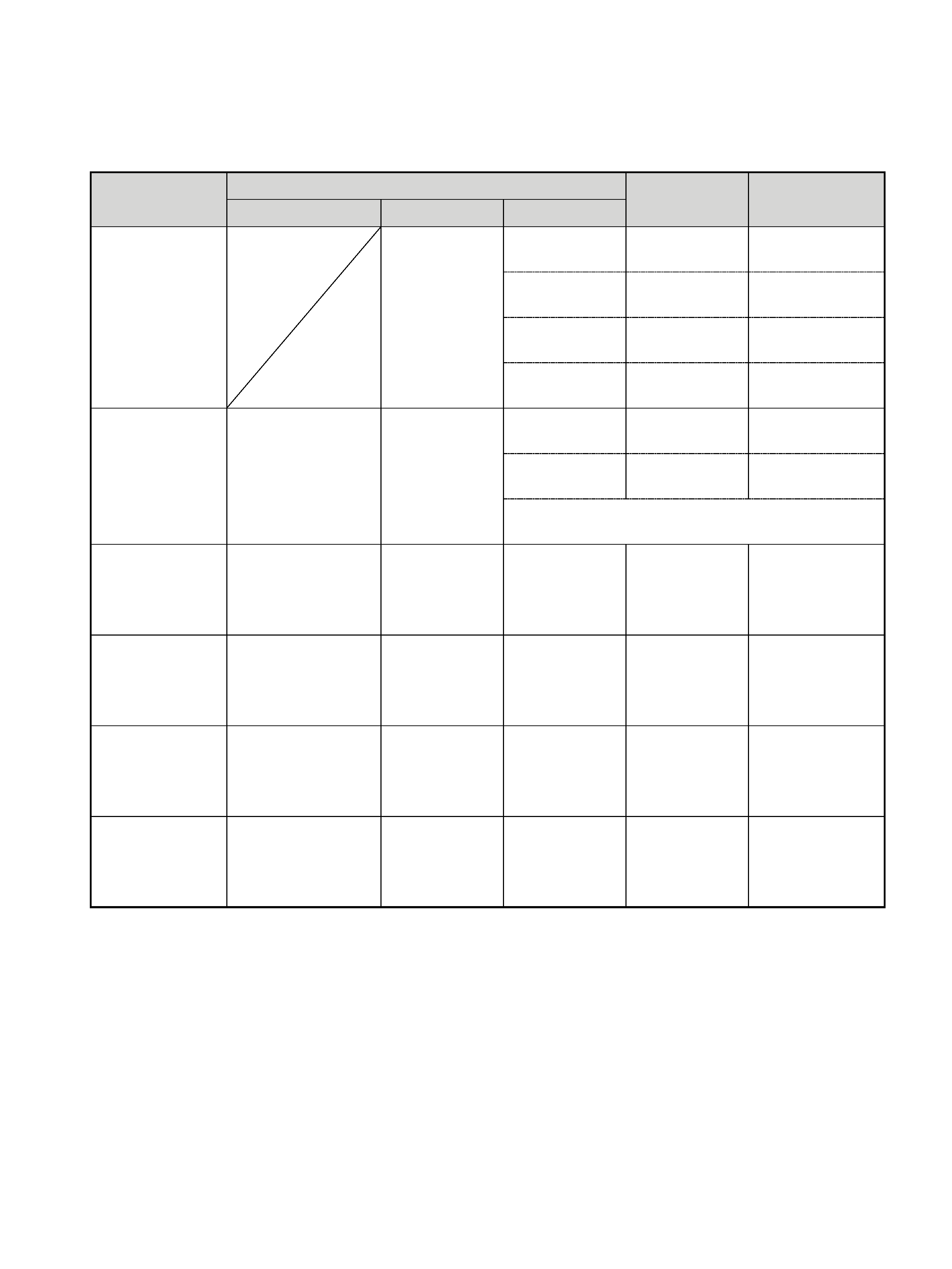
4
ITEM
SETTING
ADJUSTMENT
POINTS
ADJUST
2. AM Sensitivity
600 kHz/1500 kHz
50 dB/m
400 Hz (30 % Mod)
ç
REC OUT
AM 600 kHz
2T1 (BLK)
Max.
3. AM IF
1000 kHz
50 dB/m
400 Hz (30 % Mod)
ç
REC OUT
AM 1000 kHz
2T3 (WHT)
Max.
4. FM Sensitivity
90 MHz
10~20 dBf
1 kHz (100 % Mod)
REC OUT
FM 90 MHz
2L2 (4.5T)
Max.
5. FM Distortion
98 MHz
60 dBf
1 kHz (100 % Mod)
©
REC OUT
FM 98 MHz
2T4 (PINK)
Min. distortion
6. FM Stereo
é
98 MHz
60 dBf
Stereo signal L-R
©
REC OUT
FM 98 MHz
2T5, 2T6
Min. distortion
1. VT Adjust
å
2R19 (VT)
2J2 (GND)
FM 87.5 MHz
2L3 (3.5T)
DC 1.0 0.05V
INPUT
OUTPUT
AG-370
After adjusting 2TC2, readjust 2T1 at 600 kHz.
AM 1500 kHz
2TC2
Max.
AM 1720 kHz
AM 530 kHz
FM 108.0 MHz
Check
2T2 (RED)
Check
8.0V
DC 1.1 0.05V
DC 8.0 0.5V
2-2 TUNER SECTION
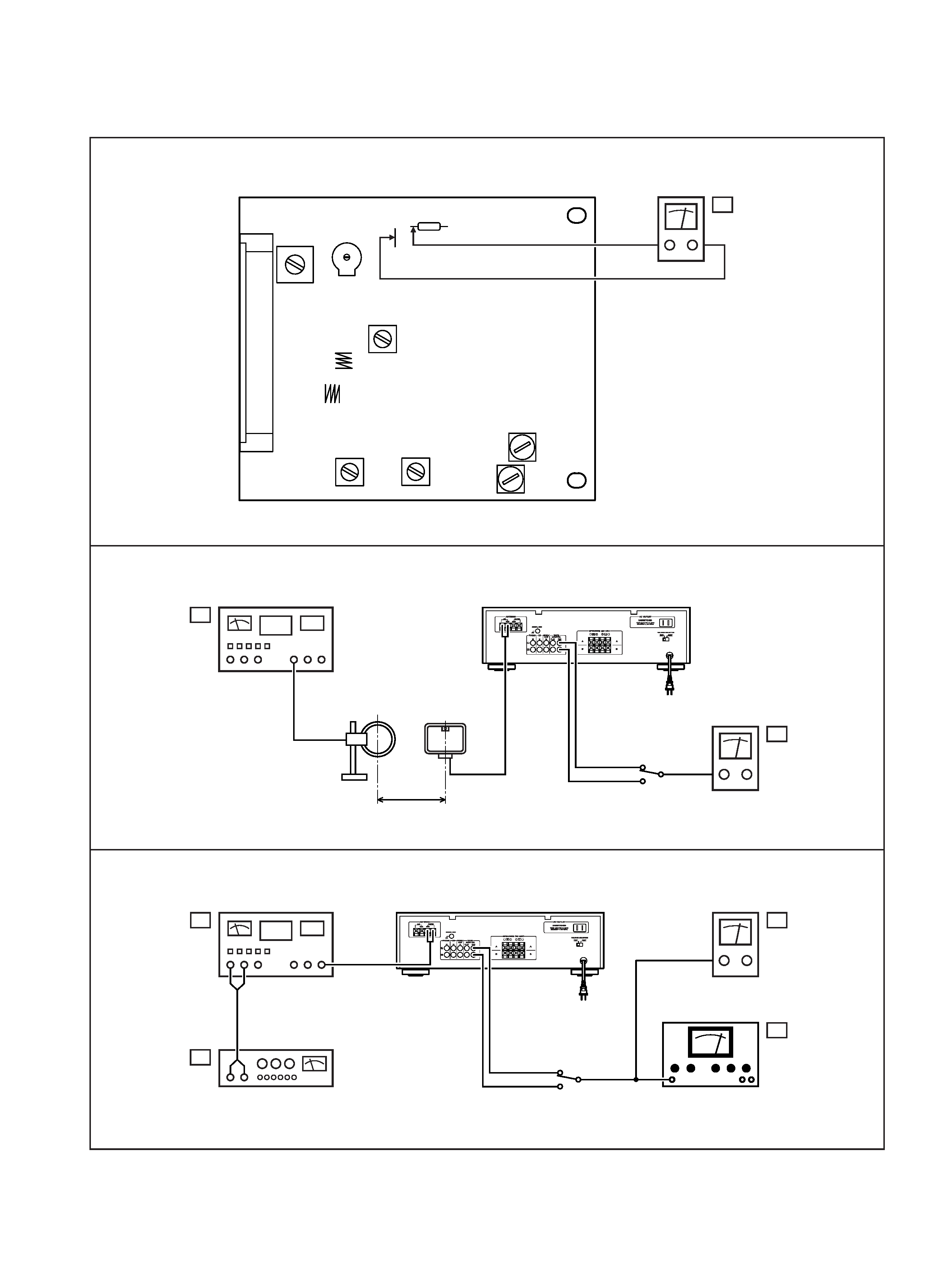
5
AC Voltmeter
FM Signal Generator
Stereo Signal Generator
Distortion Analyzer
D
E
G
F
AC Voltmeter
AM Signal Generator
B
C
AM Loop
Antenna
60cm
2T3
2T6
2T5
2T2
2T1
2T4
2L2
2L3
2TC2
2R19
2J2
TUNER PCB
DC Voltmeter
A