Ver 1.1 2001.04
Model Name Using Similar Mechanism
CD Mechanism Type
Optical Pick-up Name
Model Name Using Similar Mechanism
MD Mechanism Type
Optical Pick-up Name
ZS-M30
SERVICE MANUAL
PERSONAL MINIDISC SYSTEM
SPECIFICATIONS
AEP Model
UK Model
Australian Model
US and foreign patents licensed from Dolby
Laboratories Licensing Corporation
CD player section
System
Compact disc digital audio system
Laser diode properties
Material: GaAlAs
Wave length: 785 nm
Emission duration: Continuous
Laser output: Less than 44.6
µW
(This output is the value measured at a distance of about 200 mm
from the objective lens surface on the optical pick-up block with 7
mm aperture.)
Spindle speed
200 r/min (rpm) to 500 r/min (rpm) (CLV)
Number of programme positions
2
Frequency response
20 - 20 000 Hz +1/2 dB
Wow and flutter
Below measurable limit
Radio section
Frequency range
FM: 87.5 - 108 MHz
MW:531 - 1,602 kHz (9 kHz step)
530 - 1,610 kHz (10 kHz step)
LW: 153 - 279 kHz
IF FM: 10.7 MHz
MW/LW: 450 kHz
Aerials
FM: Telescopic aerial
MW/LW: External aerial terminals
MD player section
System
Minidisc digital audio system
Disc
MiniDisc
Laser diode properties
Material: GaAlAs
Wave length: 785 nm
Emission duration: Continuous
Laser output: Less than 44.6
µW
(This output is the value measured at a distance of about 200 mm
from the objective lens surface on the optical pick-up block with 7
mm aperture.)
Recording/playback time
Stereo recording:
Maximum 80 minutes (with MDW-80)
Monaural recording:
Maximum 160 minutes (with MDW-80)
Revolutions
400 rpm to 900 rpm (CLV)
Error correction
Advanced Cross Interleave Reed Solomon Code (ACIRC)
Sampling frequency
44.1 kHz
Coding
Adaptive Transform Acoustic Coding (ATRAC)
9-873-011-12
2001D0200-1
© 2001.4
Sony Corporation
Personal Audio Company
Shinagawa Tec Service Manual Production Group
NEW
KSM-213CDP
KSS-213C
NEW
MT-ZSM30-168
KMS-260B
CD
Section
MD
Section

2
ZS-M30
Modulation system
EFM (Eight-to-Fourteen Modulation)
Number of programme positions
2 stereo programme positions
Frequency response
20 - 20,000 Hz +1/2 dB
Signal-to-noise ratio
Over 80 dB (during playback)
Wow and flutter
Below measurable limit
General
Speaker
Full-range: 8 cm (3 1 /4 in.) dia., 4
cone type (2)
Panorama sound: 5 cm (2 in.) dia., 12
cone type (2)
Inputs
LINE IN (stereo minijack): Sensitivity 436 mV/870 mV
Outputs
Headphones jack (stereo minijack) (1):
For 32
impedance headphones
Maximum power output
Full-range: 8 W
Panorama sound: 3.4 W
Specifications ........................................................................... 1
1. SERVICING NOTE
1-1. Notes on Handling the Optical Pick-up Block or
Base Unit ............................................................................ 3
1-2. Notes on Laser Diode Emission Check .............................. 3
1-3. Notes on Chip Component Replacement ........................... 3
1-4. Flexible Circuit Board Repairing ....................................... 3
1-5. Chuck Plate Jig on Repairing ............................................. 3
1-6. Checking the Laser Diode and Focus Search Operation .... 3
1-7. Checks Prior to Parts Replacement and Adjustments
(for MD Section) ............................................................... 4
2. GENERAL
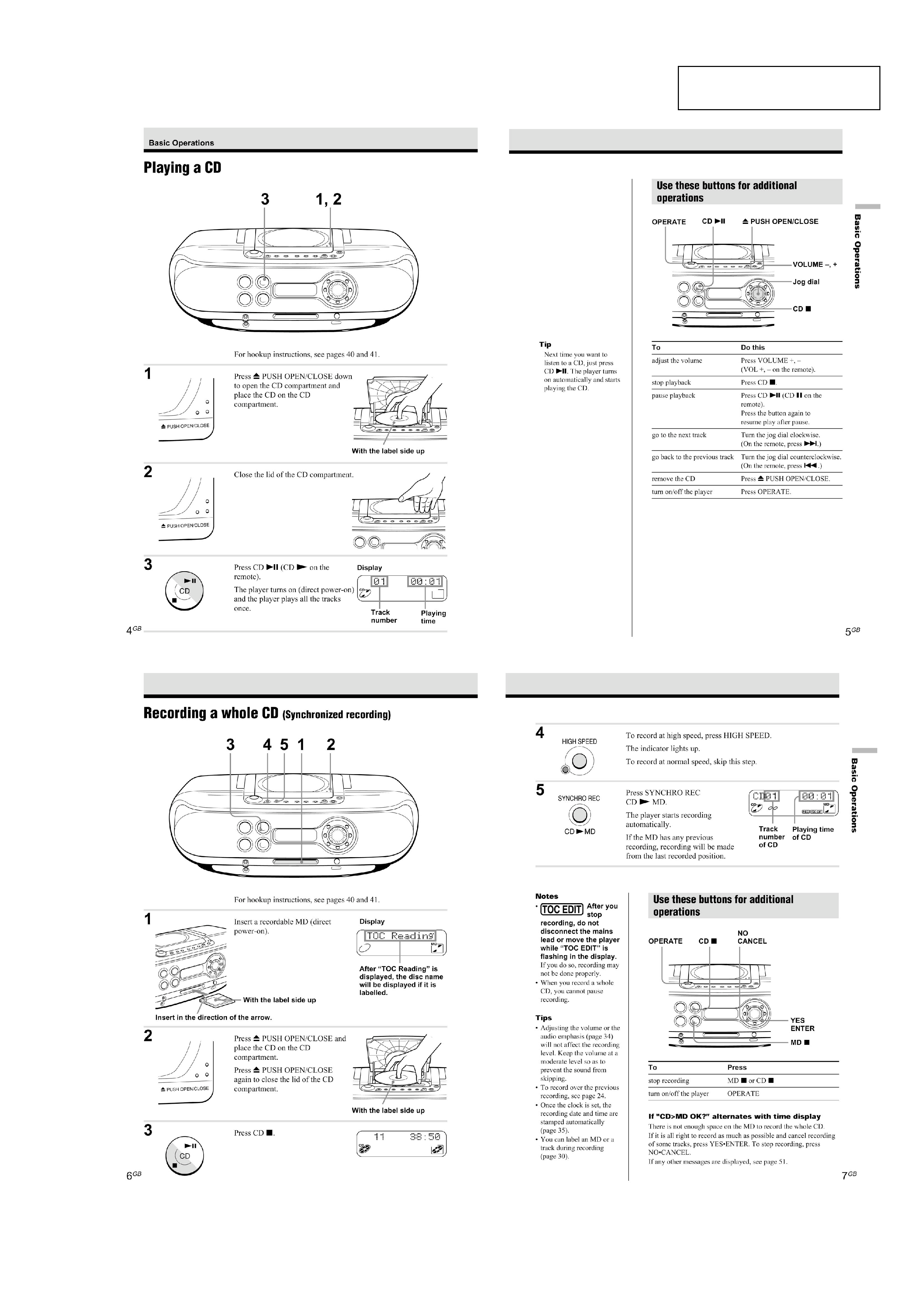
Playing a CD ...................................................................... 5
Recording a Whole CD (Synchronized Recording) ........... 5
Playing an MD ................................................................... 6
Listening to the Radio ........................................................ 6
3. DISASSEMBLY
3-1. Cabinet (Rear), Cabinet (Front) ......................................... 7
3-2. BATT (B) Board, BATT (A) Board, Power Board ............. 7
3-3. Cabinet (Upper) ASSY ....................................................... 8
3-4. Main Board, LCD Board .................................................... 8
3-5. CD Board ........................................................................... 9
3-6. Top Board ........................................................................... 9
3-7. Tuner Board ........................................................................ 9
3-8. MD Block ASSY .............................................................. 10
3-9. SW (L) Board, Jack Board, SW (R) Board ...................... 10
3-10. MD Board ...................................................................... 11
3-11. REC Board, DETECT Board ......................................... 11
3-12. Over Write Head (HR901), MD Optical Pick-up,
D SW Board ................................................................... 12
4. TEST MODE
4-1. MD Section ...................................................................... 13
4-2. Section the Test Mode ...................................................... 13
4-3. Releasing the Test Mode .................................................. 13
4-4. Basic Operations of the Test Mode .................................. 13
4-5. Selecting the Test Mode ................................................... 14
4-6. Functions of Other Buttons .............................................. 16
4-7. Test Mode Displays .......................................................... 16
4-8. Meanings of Other Displays ............................................. 16
TABLE OF CONTENTS
Power requirements
For personal minidisc system:
230 V AC, 50 Hz
For back-up memory:
4.5 V DC, 3 R6 (size AA) batteries
For remote control:
3 V DC, 2 R6 (size AA) batteries
Power consumption
26 W
Dimensions (incl.projecting parts)
approx. 475 X 165.5 X 249 mm (w/h/d)
(18 3/4 X 6 5 /8 X 9 7/8 inches )
Mass
approx. 4.6 kg (10 lb. 2 oz)
Supplied accessories
Mains lead (1)
Remote control (1)
MW/LW loop aerial (1)
AV connecting cord (1)
Audio connecting cord (1)
Design and specifications are subject to change without
notice.
5. ELECTRICAL ADJUSTMENT
5-1. Tuner Section ................................................................... 17
5-2. MD section ....................................................................... 19
5-3. CD section ........................................................................ 25
6. DIAGRAMS
6-1. IC Pin Function Descriptions ........................................... 28
6-2. Block Diagrams (1/4) ....................................................... 37
6-3. Block Diagrams (2/4) ....................................................... 38
6-4. Block Diagrams (3/4) ....................................................... 39
6-5. Block Diagrams (4/4) ....................................................... 40
6-6. Printed Wiring Boards -Main Section- ............................. 41
6-7. Schematic Diagram -Main Section (1/3)- ........................ 42
6-8. Schematic Diagram -Main Section (2/3)- ........................ 43
6-9. Schematic Diagram -Main Section (3/3)- ........................ 44
6-10. Printed Wiring Boards -Power Section- ......................... 45
6-11. Printed Wiring Boards -Tuner Section- .......................... 46
6-12. Schematic Diagram -Tuner Section- .............................. 47
6-13. Printed Wiring Boards -Control Section- ....................... 48
6-14. Schematic Diagram -Control Section- ........................... 49
6-15. Printed Wiring Boards -CD Section- .............................. 50
6-16. Schematic Diagram -CD Section- .................................. 51
6-17. Printed Wiring Boards -MD Section- ............................. 52
6-18. Schematic Diagram -MD Section (1/2)- ........................ 53
6-19. Schematic Diagram -MD Section (2/2)- ........................ 54
7. EXPLODED VIEWS
7-1. Rear Cabinet Section ........................................................ 64
7-2. Front Cabinet Section ....................................................... 65
7-3. Upper Cabinet Section ..................................................... 66
7-4. Optical Pick-up Section .................................................... 67
7-5. MD Section -1 .................................................................. 68
7-6. MD Section -2 .................................................................. 69
8. ELECTRICAL PARTS LIST .................................... 70
3
ZS-M30
1-1. NOTES ON HANDLING THE OPTICAL PICK-UP
BLOCK OR BASE UNIT
The laser diode in the optical pick-up block may suffer electro-
static break-down because of the potential difference generated
by the charged electrostatic load, etc. on clothing and the human
body.
During repair, pay attention to electrostatic break-down and also
use the procedure in the printed matter which is included in the
repair parts.
The flexible board is easily damaged and should be handled
with care.
1-2. NOTES ON LASER DIODE EMISSION CHECK
The laser beam on this model is concentrated so as to be focused
on the disc reflective surface by the objective lens in the optical
pick-up block. Therefore, when checking the laser diode emis-
sion,observe from more than 30 cm away from the objectivelens.
1-3. NOTES ON CHIP COMPONENT REPLACEMENT
· Never reuse a disconnected chip component.
· Notice that the minus side of a tantalum capacitor may be dam-
aged by heat.
1-4. FLEXIBLE CIRCUIT BOARD REPAIRING
· Keep the temperature of the soldering iron around 270
°C dur-
ing repairing.
· Do not touch the soldering iron on the same conductor of the
circuit board (within 3 times).
· Be careful not to apply force on the conductor when soldering
or unsoldering.
SAFETY-RELATED COMPONENT WARNING!!
COMPONENTS IDENTIFIED BY MARK 0 OR DOTTED
LINE
WITH MARK 0 ON THE SCHEMATIC DIAGRAMS AND IN
THE PARTS LIST ARE CRITICAL TO SAFE OPERATION.
REPLACE THESE COMPONENTS WITH SONY PARTS
WHOSE
PART NUMBERS APPEAR AS SHOWN IN THIS MANUAL
OR IN SUPPLEMENTS PUBLISHED BY SONY.
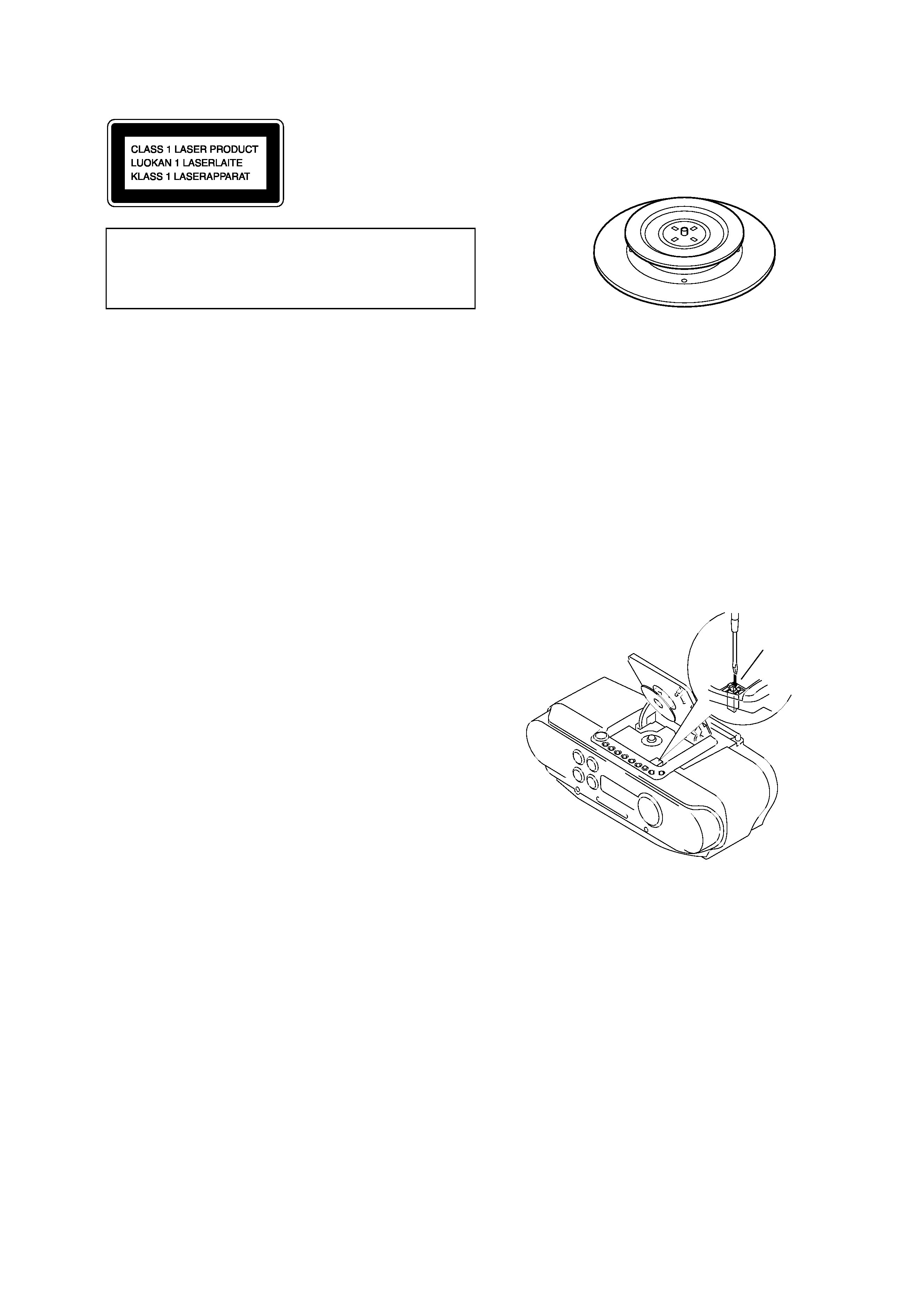
1-6. CHECKING THE LASER DIODE AND FOCUS
SEARCH OPERATION
1. Turn on the POWER and open the CD cover.
2. As shown below, push S701 (CD DOOR) with a screwdriver or
other tool.
3. Press the CD button.
4. Check the objective lens to make sure that the laser diode is
emitting light. If not so, the auto power control circuit or
optical pickup would be damaged.
Verify that the objective lens moves vertically three times for
focus search.
This Compact Disc player
is classified as a CLASS 1
LASER product.
The CLASS 1 LASER
PRODUCT label is located
on the bottom exterior.
CAUTION
Use of controls or adjustments or performance of proce-
duresother than those specified herein may result in haz-
ardous radiation exposure.
1-5. CHUCK PLATE JIG ON REPAIRING
On repairing CD section, playing a disc without the CD lid, use
Chuck Plate Jig.
· Code number of Chuck Plate Jig: X-4918-255-1
Insert a precision
screw driver and push
SWITCH (S701)
SECTION 1
SERVICE NOTE

4
ZS-M30
1-7. CHECKS PRIOR TO PARTS REPLACEMENT AND ADJUSTMENTS (FOR MD SECTION)
Before performing repairs, perform the following checks to determine the faulty locations up to a certain extent.
Details of the procedures are described in "5 Electrical Adjustments"
Laser power check
Criteria for Determination
(Unsatisfactory if specified value is not satisfied)
Note:
The criteria for determination above is intended merely to determine if satisfactory or not, and does not serve as the specified value for
adjustments.
When performing adjustments, use the specified values for adjustments.
Measure if unsatisfactory:
· Clean the optical pick-up
· Adjust again
· Replace the optical pick-up
· 0.9 mW power
Specified value : 0.80 to 0.96 mW
· 7.0 mW power
Specified value : 6.8 to 7.2 mW
lop (at 7mW)
· Labeled on the optical pickup
Iop value
± 10%
· Replace the optical pick-up
If always unsatisfactory:
· Replace the overwrite head
· Check for disconnection of the circuits around the
overwrite head
If occasionally unsatisfactory:
· Check if the overwrite head is distorted
· Check the mechanism around the sled
· Error rate check
Specified value : For points a and b
C1 error : About 200
ADER : Below 2
Point C
C1 error :Below 50
AD error :Below 2
· Error rate check
Specified value:
a. When using test disc (MDW-74/AU-1)
C1 error : Below 80
ADER : Below 2
b. When using check disc (TDYS-1)
C1 error : Below 50
· CPLAY error rate check
Specified value:
C1 error : Below 80
ADER : Below 2
· Replace the optical pick-up
· Replace the optical pick-up
Focus power check
C PLAY check
Self-recording/playback
check
5
ZS-M30
SECTION 2
GENERAL
This section is extracted from
instruction manual.