ZS-D55
SERVICE MANUAL
PERSONAL AUDIO SYSTEM
SPECIFICATIONS
AEP Model
UK Model
Tourist Model
TAPE
Model Name Using Similar Mechanism
NEW
Section
Tape Transport Mechanism Type
MF-ZSD55
CD
Model Name Using Similar Mechanism
ZS-D50
Section
MD Mechanism Type
CDM-2411AAA
Optical Pick-up Type
DAX-01A2
Continued on page 2
CD player section
System
Compact disc digital audio system
Laser diode properties
Material: GaAlAs
Wave length: 780 nm
Emission duration: Continuous
Laser output: Less than 44.6
µW (This output is the value measured
at a distance of about 200 mm from the objective lens surface on the
optical pick-up block with 7 mm aperture.)
Spindle speed
200 r/min (rpm) to 500 r/min (rpm) (CLV)
Number of channels
2
Frequency response
20 - 20 000 Hz +0.5/1.2 dB
Wow and flutter
Below measurable limit
Radio section
Frequency range
FM
: 87.5 - 108 MHz
MW
: 531 - 1602 kHz
LM
: 153 - 279 kHz
IF
FM
: 10.7 MHz
MW/LW : 450 kHz
Aerials
FM
: Telescopic aerial
MW/LW : Built-in ferrite bar aeraial
Cassette-corder section
Recording system
4-track 2 channel stereo
Fast winding time
Approx. 112 s (sec.) with Sony cassette C-60
Frequency response
TYPE I (normal): 50 - 15 000 Hz
General
Speaker
Full range: 8 cm (3 1/4 in.) dia., 12
,
cone type x 2
Input
LINE IN jack (stereo minijack)
Minimum input level 138 mV
Outputs
Headphones jack (stereo minijack)
For 8 - 32
impedance headphones
LINE OUT jack (stereo minijack)
Rated output level 138 mV at load impedance
47 k
OPTICAL DIGITAL OUT (CD) (optical output connector)
Wavelength: 630 - 690 nm
Maximum power output
5 W + 5 W
Ver 1.1 2002. 02
9-927-927-32
2002B0200-1
© 2002.02
Sony Corporation
Personal Audio Company
Published by Sony Engineering Corporation

2
Specifications ........................................................................... 1
1. SERVICE NOTE ........................................................... 3
2. GENERAL ...................................................................... 4
3. DISASSEMBLY
3-1. Cabinet Rear ASSY, Cabinet Front ASSY ................ 6
3-2. Power Board, P/T In Board, P/T Out Board,
BATT S Board ........................................................... 7
3-3. Tuner Board .............................................................. 7
3-4. Jack Board ................................................................. 7
3-5. Audio Board .............................................................. 8
3-6. CD Board .................................................................. 8
3-7. TC Board ................................................................... 9
3-8. Cabinet Top ASSY .................................................... 9
3-9. H/P Board ................................................................ 10
3-10. TC/M Board ............................................................ 10
3-11. MD Block ASSY ...................................................... 11
3-12. TC LED (L) Board, TC LED (R) Board,
TC Key Board .......................................................... 11
3-13. TC RF Board, Head Relay Board, Belt FR,
Belt BR, Capstan/Reel Motor (M691) .................... 12
3-14. CD Chassis ASSY ................................................... 12
3-15. CD Block Section ................................................... 13
3-16. Loading Board ........................................................ 13
3-17. "Tray ASSY, CD" ................................................... 14
3-18. Optical Pick-up Block, Pick-up Relay Board ......... 14
3-19. Panel DECO ASSY ................................................ 15
3-20. Control Board, JOG LED1 Board,
JOG LED2 Board .................................................... 15
3-21. Key Board ............................................................... 16
TABLE OF CONTENTS
3-22. BATT Board ........................................................... 16
4. TEST MODE ................................................................ 17
5. ADJUSTMENTS
5-1. Mechanical Adjustmens ............................................ 18
5-2. Electrical Adjustments .............................................. 19
6. DIAGRAMS
6-1. Explanation of IC Terminals ................................... 22
6-2. Block Diagrams (Tape, Main Section) ................... 24
6-3. Block Diagrams (Tuner, CD Section) .................... 27
6-4. Printed Wiring Boards (Main Section) ................... 31
6-5. Schematic Diagram (Main Section) ....................... 35
6-6. Schematic Diagram (CD Section) .......................... 39
6-7. Printed Wiring Boards (CD Section) ...................... 43
6-8. Printed Wiring Boards (Contorl Section) ............... 45
6-9. Schematic Diagram (Control Section) .................... 47
6-10. Printed Wiring Boards (Tuner Section) .................. 51
6-11. Schematic Diagram (Tuner Section) ...................... 52
7. EXPLODED VIEWS
7-1. Rear Cabinet Section ................................................ 60
7-2. Front Cabinet Section ............................................... 61
7-3. CD Block Section ..................................................... 62
7-4. Top Cabinet Section .................................................. 63
7-5. Mechanism Deck Section (1/2) ................................ 64
7-6. Mechanism Deck Section (2/2) ............................... 65
7-7. CD Section ................................................................ 66
7-8. Optical Pick-up Section ............................................ 67
8. ELECTRICAL PARTS LIST ................................... 68
Power requirements
For personal audio system:
230V AC, 50 Hz
12 V DC, 8 R20 (size D) batteries
For memory back-up:
6 V DC, 4 R6 (size AA) batteries
For remote control:
3 V DC, 2 R6 (size AA) batteries
Power consumption
AC 20 W
Battery life
For personal audio system
FM recording
Sony R20P: approx. 6 h
Sony alkaline LR20: approx. 12 h
Tape playback
Sony R20P: approx. 3 h
Sony alkaline LR20: approx. 6 h
CD playback
Sony R20P: approx. 1.5 h
Sony alkaline LR20: approx. 3 h
Dimensions (incl. projecting parts)
Approx. 486 x 244 x 177 mm (w/h/d)
(17 1/10 x 9 3/5 x 6 9/10 inches)
Mass (incl. batteries)
Approx. 6.2 kg (13 lb. 11 oz)
Supplied accessories
Mainns Lead (1)
Remote control (1)
Design and specifications are subject to change without notice.
3
NOTES ON HANDLING THE OPTICAL PICK-UP BLOCK
OR BASE UNIT
The laser diode in the optical pick-up block may suffer electrostatic
breakdown because of the potential difference generated by the
charged electrostatic load, etc. on clothing and the human body.
During repair, pay attention to electrostatic breakdown and also use
the procedure in the printed matter which is included in the repair
parts.
The flexible board is easily damaged and should be handled with
care.
NOTES ON LASER DIODE EMISSION CHECK
The laser beam on this model is concentrated so as to be focused on
the disc reflective surface by the objective lens in the optical pick-
up block. Therefore, when checking the laser diode emission, ob-
serve more than 30 cm away from the objective lens.
LASER DIODE AND FOCUS SEARCH OPERATION
CHECK
1. Close the tray for CD.
2. Press CD u button.
3. Confirm the laser diode emission while observing the objecting
lens. When there is no emission, Auto Power Control circuit or
Optical Pick-up is broken.
Objective lens moves up and down once for the focus search.
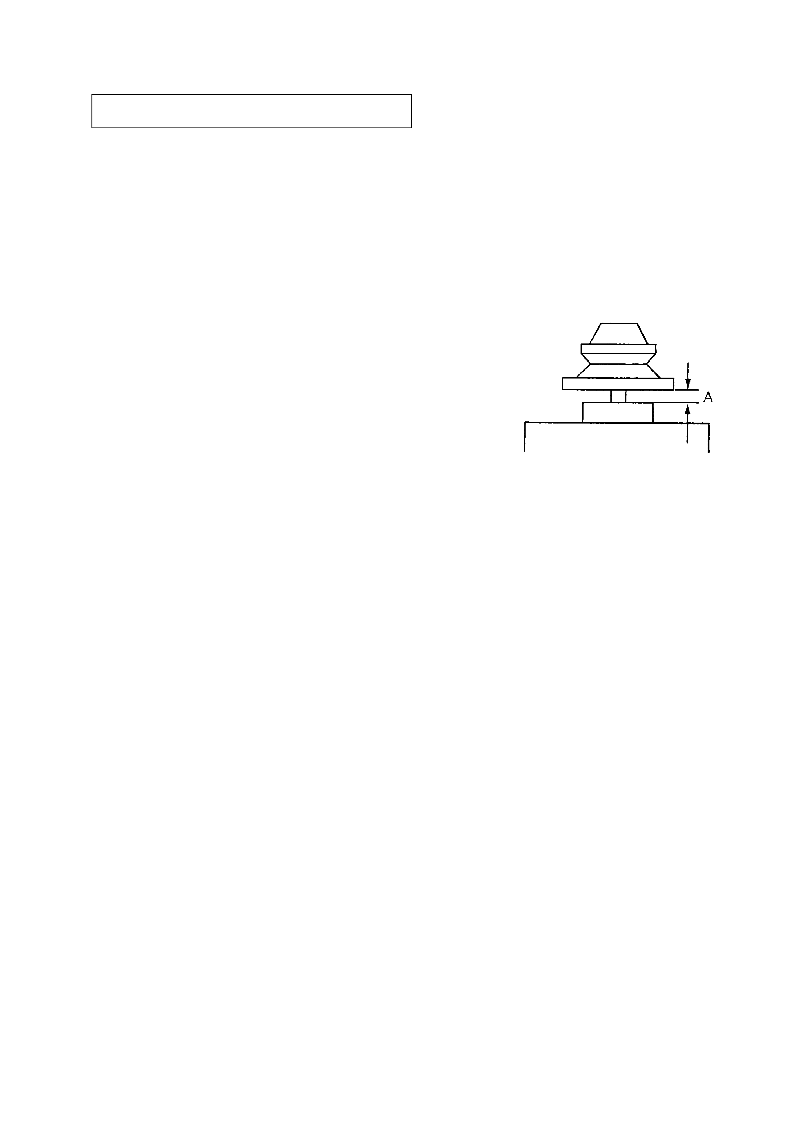
CAUTION DURING WHEN MOUNTING THE PULLEY
FOR THE LOADING MOTOR
Make the following adjustment when mounting the loading motor
(part number : 1-698-999-11) and motor pulley (part number : 2-
627-174-01) of the CD section.
Specification : A = 0.9 to 1.1mm
SECTION 1
SERVICE NOTE
4
SECTION 2
GENERAL
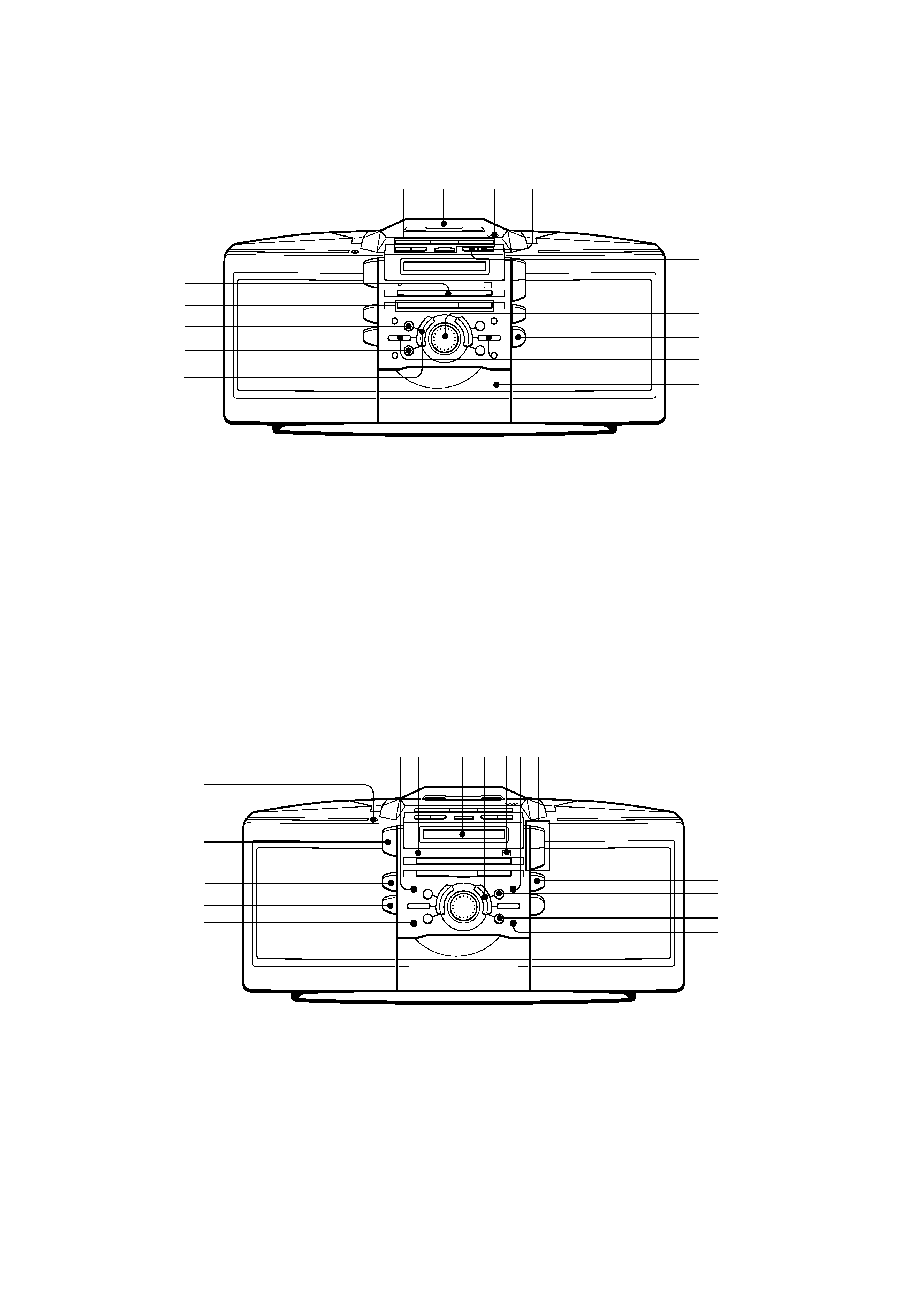
LOCATION AND FUNCTION OF CONTROLS
FRONT PANEL : CD/RADIO/TAPE section
1 Tape operation buttons
z/X (REC/REC PAUSE)
m, M (FF/REW, AMS)
x (STOP)
b, B (PLAY)
2 Cassette lid
3 Z PUSH OPEN/CLOSE
4 COUNTER RESET button
5 DIR MODE button
6 JOG dial
7 Z CD OPEN/CLOSE button
8 Radio operation buttons
Tune m, M +
9 CD tray
FRONT PANEL: TIMER/COM section
0 AUTO PRESET button
qa CANCEL button
qs CD DUB button
qd CD operation buttons
u (PLAY/PAUSE)
x (STOP)
qf BAND button
qg STANDBY button
qh OPR/BATT indicator
qj Display window
qk DISPLAY button
ql Remote control receiver
w; CLOCK button
wa VOL +, buttons
ws MEGA BASS button
wd MODE buttion
wf ENTER MEM button
wg TIMER button
wh SLEEP button
wj MD(LINE) button
wk SOUND button
wl POWER button
e; i (Headphones) jack (stereo mini jack)
12
3
4
5
6
7
8
9
qf
qd
qs
qa
0
qgqh
qj qk qlw;wa
ws
wd
wf
e;
wl
wk
wj
wh
wg
5
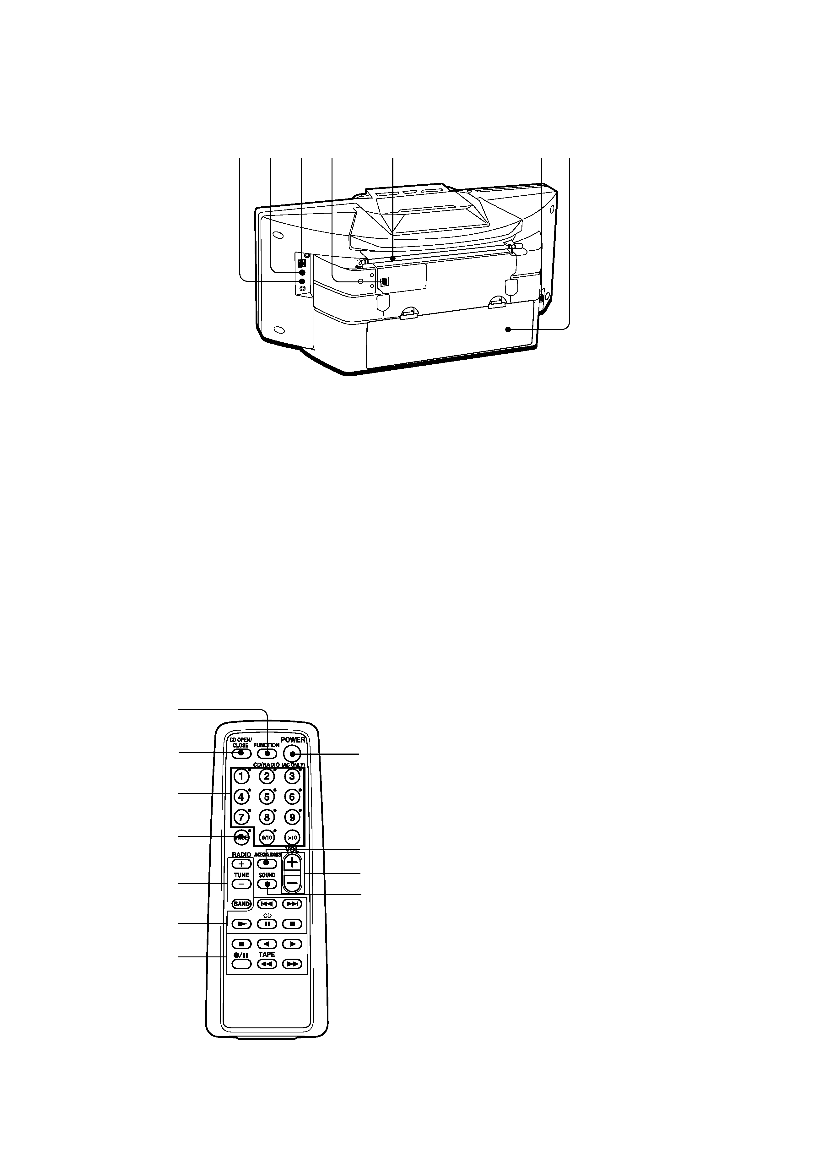
REAR PANEL
1 FUNCTION button
Each time you pressed, the function changes in the order
CD Tape Radio Line CD · · ·
2 Z CD OPEN/CLOSE button
3 Number buttons
4 MODE button
5 Radio operation buttons
TUNE +, button
BAND
6 CD operation buttons
., > (AMS/SEARCH)
N (PLAY)
X (PAUSE)
x (STOP)
7 Tape operation buttons
x (STOP)
b, B (PLAY)
z/X (REC/REC PAUSE)
m, M (FF/REW, AMS)
8 POWER button (AC only)
Active only when you use the set with AC power source.
9 MEGA BASS button
0 VOL +, button
qa SOUND button
ea LINE OUT jack
es LINE IN jack
ed OPTICAL DIGITAL OUT(CD) jack
ef OPTICAL DIGITAL OUT(CD) jack cover socket
eg FM telescopic antenna
eh AC IN - jack
ej Battery compartment
Remote commander
3
2
1
4
5
6
7
8
9
0
qa
ea es ed ef
eg
eh ej