Ver 1.0 1999.01
MICROFILM
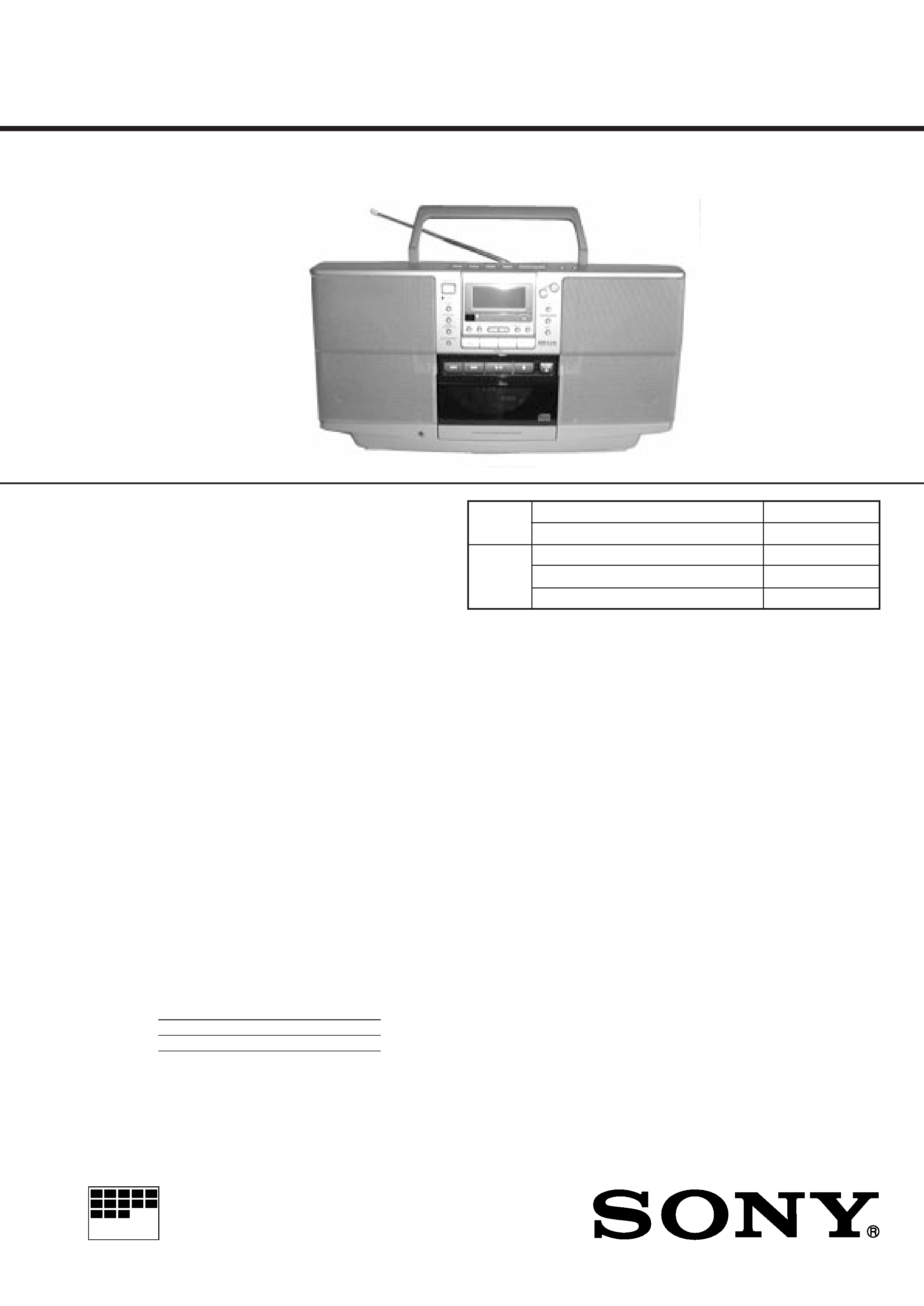
ZS-D50
SERVICE MANUAL
PERSONAL AUDIO SYSTEM
SPECIFICATIONS
AEP Model
UK Model
Tourist Model
TAPE
Model Name Using Similar Mechanism
NEW
Section
Tape Transport Mechanism Type
MF-ZSD50
CD
Model Name Using Similar Mechanism
ZS-M7
Section
MD Mechanism Type
CDM-2411AAA
Optical Pick-up Type
DAX-11A
Continued on page 2
CD player Section
System
Compact disc digital audio system
Laser diode properties
Material: GaAlAs
Wave length: 780 nm
Emission duration : Continuous
Laser output : Less than 44.6
µW
(This output is the value measured at a distance of about 200
mm from the objective lens surface on the optical pick-up
block with 7 mm aperture.)
Spindle speed
200 r / min (rpm) to 500 r / min (rpm) (CLV)
Number of channels
2
Frequency response
20 - 20,000 Hz +1 / 1 dB
Wow and flutter
Below measurable limit
Radio section
Frequency range
FM
87.5 - 108 MHz
MW
531 - 1,602 kHz
LW
153 - 279 kHz
IF
FM : 10.7 MHz
MW / LW : 450 kHz
Aerials
FM : Telescopic aerial
MW / LW : Built-in ferrite bar aerial
Cassette-corder Section
Recording System
4-track 2 channel stereo
Fast winding time
Approx. 130 s (sec.) with Sony cassette C-60
Frequency response
TYPE I (normal) : 50 - 15,000 Hz
General
Speaker
Full range : 8 cm (3 1/4 in.) dia., 3 ohms, cone type x 2
Input
LINE IN jack (stereo minijack)
Minimum input level 250 mV
Outputs
Headphones jack (stereo minijack)
For 16 - 68 ohms impedance headphones
LINE OUT jack (stereo minijack)
Rated output level 250 mV at load impedance 47 kilohms
OPTICAL DIGITAL OUT (CD) (optical output connector)
Wavelength : 630 - 690 nm
Maximum power outputs
4.5 W + 4.5 W

2
Specifications ........................................................................... 1
1. SERVICE NOTE ........................................................... 3
2. GENERAL ...................................................................... 4
3. DISASSEMBLY
3-1. "Cabinet, Rear", "Cabinet Sub ASSY, Front" ............ 6
3-2. Inlet Board, Power Board ........................................... 7
3-3. Battery (R) Board, Battery (L) Board ......................... 7
3-4. Cabinet (Upper) ASSY ............................................... 7
3-5. Switch (1) Board ......................................................... 8
3-6. Mechanism Deck ........................................................ 8
3-7. Line Board .................................................................. 8
3-8. Tuner Board ................................................................ 8
3-9. CD Block ASSY ......................................................... 9
3-10. Headphone Board ..................................................... 9
3-11. Switch (2) Board, LCD Board, Lamp Board .......... 10
3-12. Main Board, CD/System Board .............................. 10
3-13. CD Block Section .................................................... 11
3-14. TC RF Board, Head Relay Board,
Belt (FR/BR), Motor (M691) .................................. 11
3-15. Tray ASSY, CD ....................................................... 12
3-16. Loading Board ........................................................ 12
3-17. Optical Pick-up Block, Pick-up Relay Board ......... 12
4. TEST MODE ................................................................ 13
TABLE OF CONTENTS
5. ADJUSTMENTS
5-1. Mechanical Adjustmens ............................................ 14
5-2. Electrical Adjustments .............................................. 14
6. DIAGRAMS
6-1. Explanation of IC Terminals ..................................... 18
6-2. Block Diagrams (Tape, Main Section) ..................... 20
6-3. Block Diagrams (Tuner, CD Section) ....................... 23
6-4. Printed Wiring Boards (Main Section) ..................... 27
6-5. Schematic Diagram (Main Section) ......................... 31
6-6. Printed Wiring Boards (CD/System Section) ........... 36
6-7. Schematic Diagram (CD/System Section) ............... 41
6-8. Printed Wiring Boards (Tuner Section) .................... 46
6-9. Schematic Diagram (Tuner Section) ........................ 48
7. EXPLODED VIEWS
7-1. Rear Cabinet Section ................................................ 56
7-2. Front Cabinet Section ............................................... 57
7-3. CD Block Section ..................................................... 58
7-4. Mechanism Deck Section -1 ..................................... 59
7-5. Mechanism Deck Section -2 ..................................... 60
7-6. CD Section ................................................................ 61
7-7. Optical Pick-up Section ............................................ 62
8. ELECTRICAL PARTS LIST ................................... 63
Power requirements
For personal audio system :
230V AC, 50 Hz
12 V DC, 8 R20 (size D) batteries
For memory back-up :
6 V DC, 4 R6 (size AA) batteries
For remote commander :
3 V DC, 2 R6 (size AA) batteries
Power consumption
AC 27 W
Battery life
For personal audio system
FM recording
Sony R20P : approx. 6 h
Sony alkaline LR20 : approx. 12 h
Tape playback
Sony R20P : approx. 3 h
Sony alkaline LR20 : approx. 6 h
CD playback
Sony R20P : approx. 1.5 h
Sony alkaline LR20 : approx. 3h
Dimensions (incl. projecting parts)
Approx. 435 x 223 x 160 mm (w / h / d)
(17 1/4 x 8 7/8 x 6 1/8 inches)
Mass (incl. batteries)
approx. 4.3 kg (9 lb. 7 oz)
Supplied accessories
AC power cord (1)
Remote commander (1)
Plug adaptor (1) (UK)
Design and specifications are subject to change without notice.
3
NOTES ON HANDLING THE OPTICAL PICK-UP BLOCK
OR BASE UNIT
The laser diode in the optical pick-up block may suffer electrostatic
breakdown because of the potential difference generated by the
charged electrostatic load, etc. on clothing and the human body.
During repair, pay attention to electrostatic breakdown and also use
the procedure in the printed matter which is included in the repair
parts.
The flexible board is easily damaged and should be handled with
care.
NOTES ON LASER DIODE EMISSION CHECK
The laser beam on this model is concentrated so as to be focused on
the disc reflective surface by the objective lens in the optical pick-
up block. Therefore, when checking the laser diode emission, ob-
serve more than 30 cm away from the objective lens.
LASER DIODE AND FOCUS SEARCH OPERATION
CHECK
1. Close the lid for CD.
2. Press CD
^
button.
3. Confirm the laser diode emission while observing the objecting
lens. When there is no emission, Auto Power Control circuit or
Optical Pick-up is broken.
Objective lens moves up and down once for the focus search.
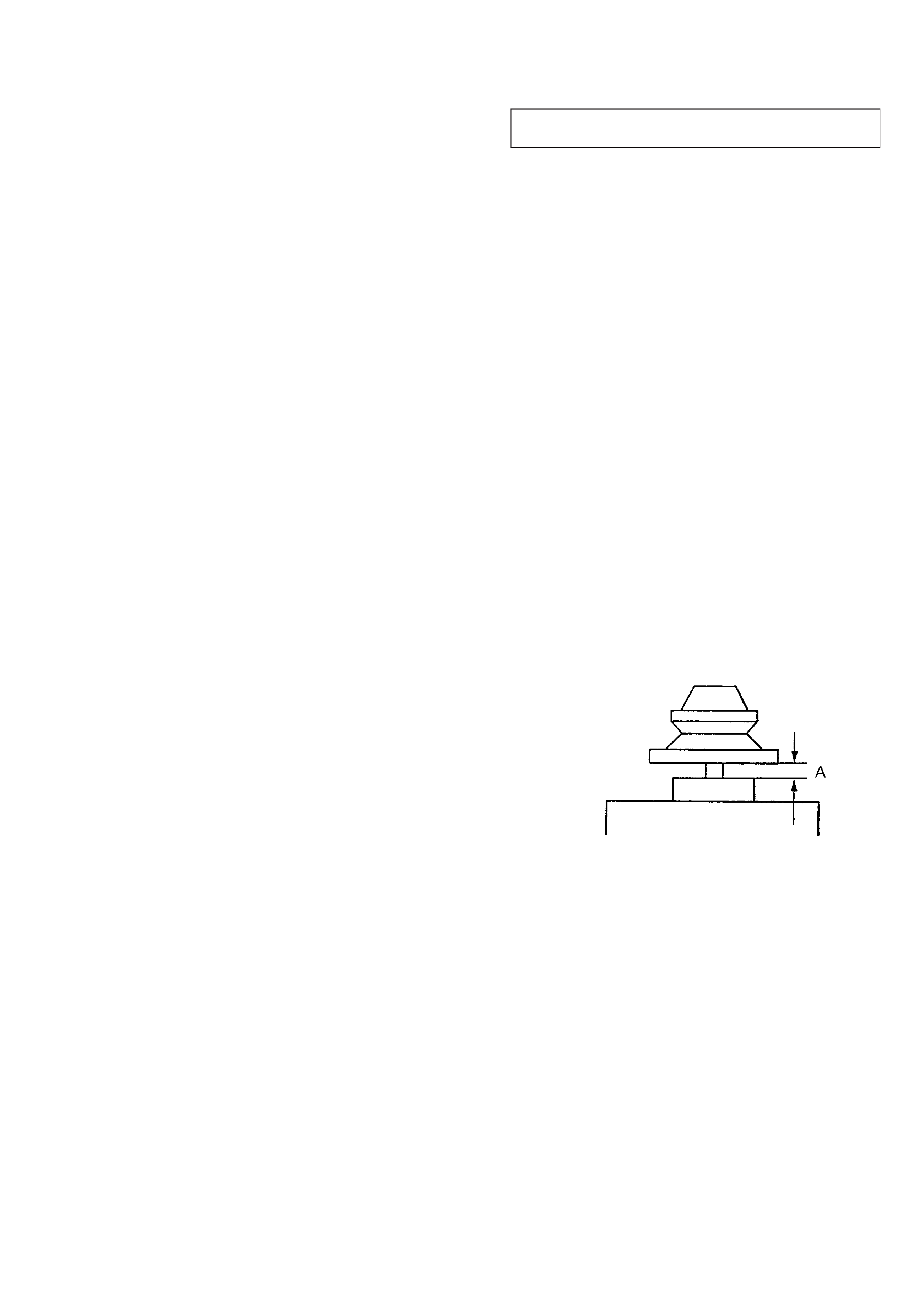
CAUTION DURING WHEN MOUNTING THE PULLEY
FOR THE LOADING MOTOR
Make the following adjustment when mounting the loading motor
(part number : 1-698-999-11) and motor pulley (part number : 2-
627-174-01) of the CD section.
Specification : A = 0.9 to 1.1mm
SECTION 1
SERVICE NOTE
SAFETY-RELATED COMPONENT WARNING!!
COMPONENTS IDENTIFIED BY MARK
! OR DOTTED LINE WITH
MARK
!ON THE SCHEMATIC DIAGRAMS AND IN THE PARTS
LIST ARE CRITICAL TO SAFE OPERATION.
REPLACE THESE COMPONENTS WITH SONY PARTS WHOSE
PART NUMBERS APPEAR AS SHOWN IN THIS MANUAL OR IN
SUPPLEMENTS PUBLISHED BY SONY.
Flexible Circuit Board Repairing
· Keep the temperature of the soldering iron around 270°C during
repairing.
· Do not touch the soldering iron on the same conductor of the
circuit board (within 3 times).
· Be careful not to apply force on the conductor when soldering or
unsoldering.
Notes on chip component replacement
· Never reuse a disconnected chip component.
· Notice that the minus side of a tantalum capacitor may be dam-
aged by heat.
4
SECTION 2
GENERAL
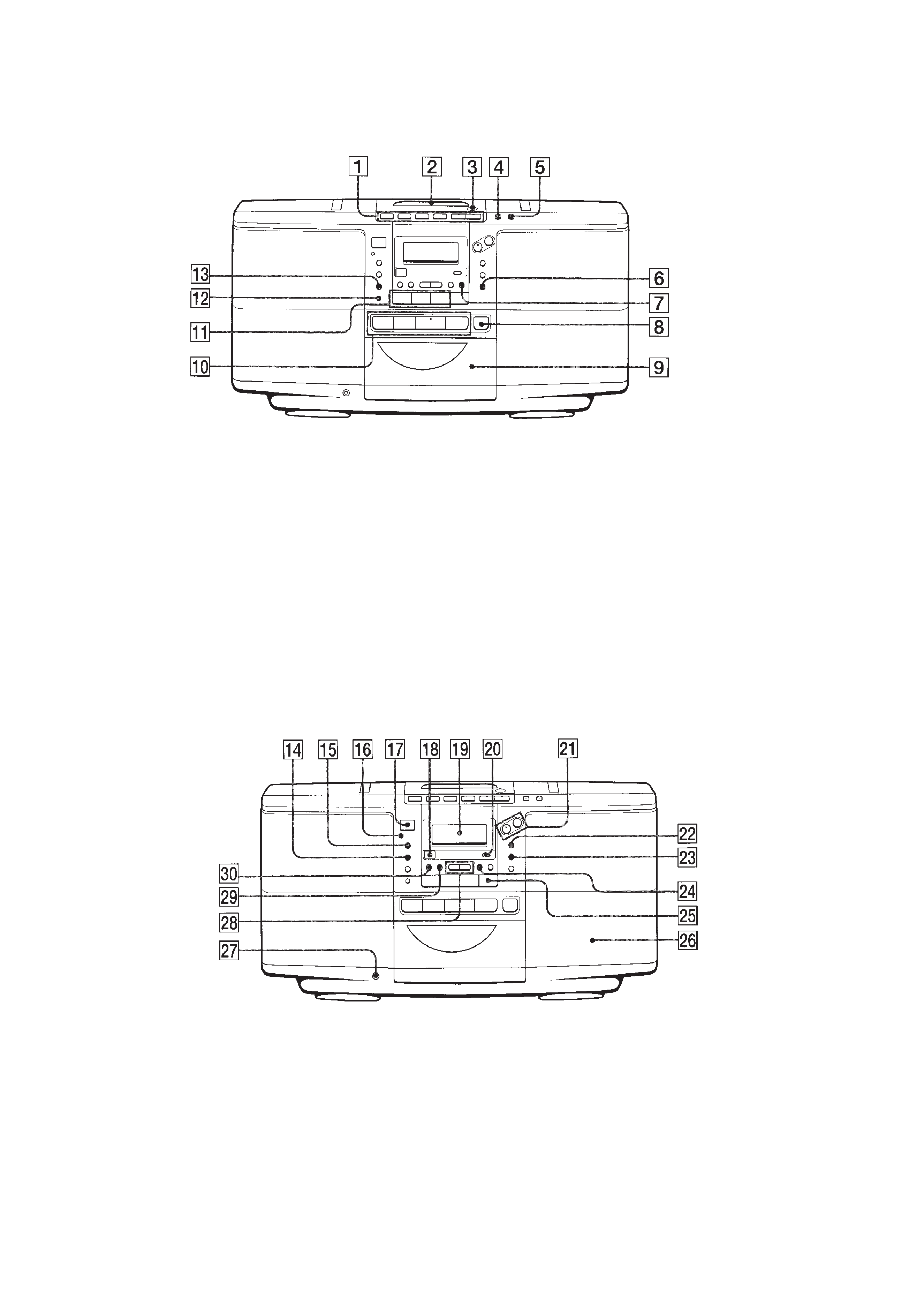
LOCATION AND FUNCTION OF CONTROLS
FRONT PANEL : CD/RADIO/TAPE section
1 Tape operation buttons
r/P (REC/REC PAUSE)
0, ) (FF/REW, AMS)
p (STOP)
9, ( (PLAY)
2 Cassette lid
3 6 PUSH OPEN/CLOSE
4 DIR MODE button
5 COUNTER RESET button
6 EDIT button
7 CANCEL button
8 6 CD OPEN/CLOSE button
9 CD tray
!º CD operation buttons
=, + (AMS/SEARCH)
^ (PLAY/PAUSE)
p (STOP)
FRONT PANEL: TIMER/COM section
!¡ Radio operation buttons
RADIO BAND
PRESET +,
!TM AUTO PRESET button
!£ MODE MONO/ST ISS button
!¢ STANDBY button
! SLEEP button
!§ OPR/BATT indicator
!¶ OPERATE button
!· Remote control receiver
!ª Display window
@º DISPLAY button
@¡ VOL +,
@TM SOUND button
@£ MEGA BASS button
@¢ ENTER/MEMORY CHECK button
@ MD(LINE) button
@§ Speaker
@¶ 2 (Headphones) jack (stereo mini jack)
@· TUNING TIME SET +, button
@ª TIMER button
#º CLOCK button
5
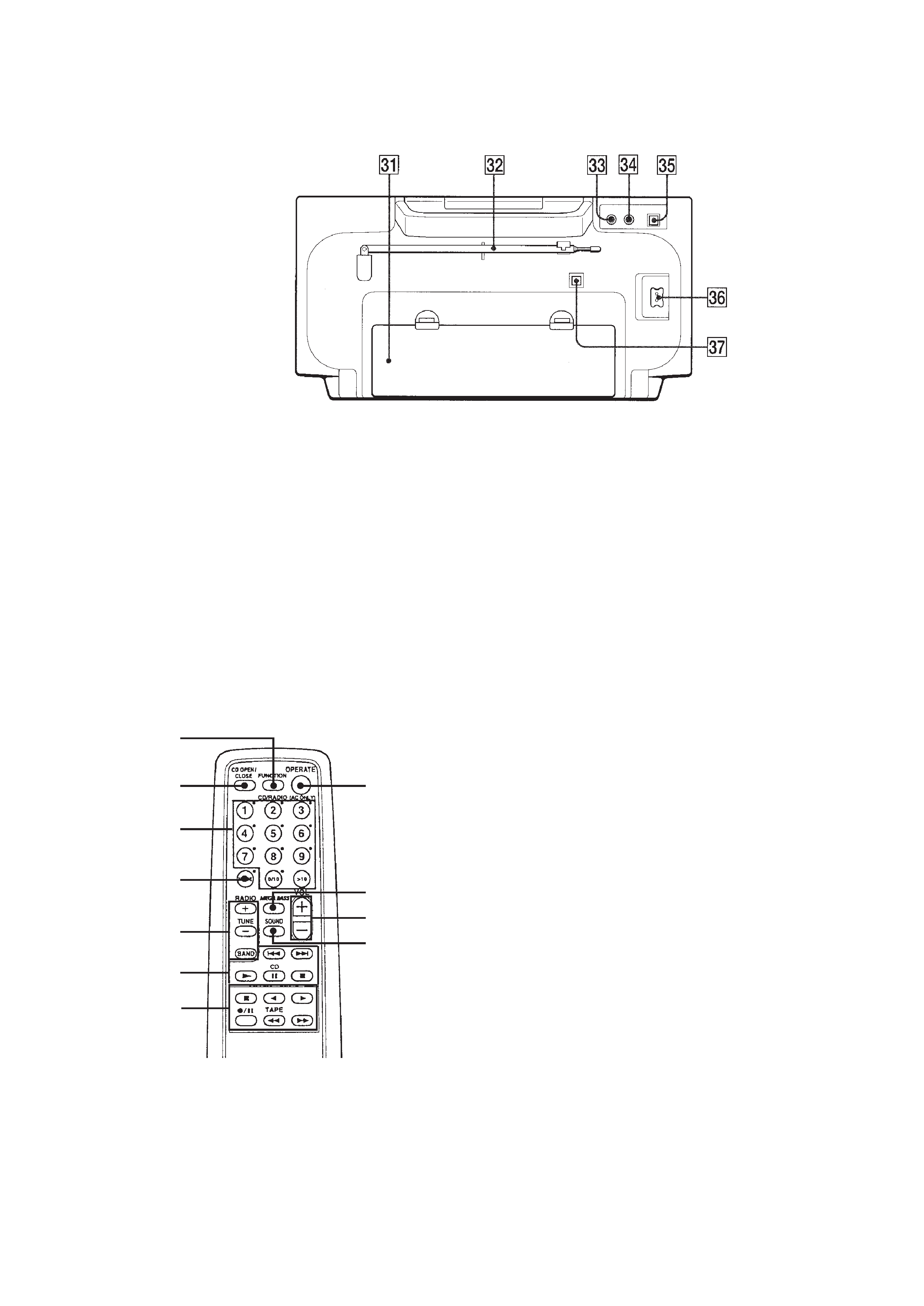
REAR PANEL
1 FUNCTION button
Each time you pressed, the function changes in the order
CD Tape Radio Line CD · · ·
2 6 CD OPEN/CLOSE button
3 Number buttons
4 MODE button
5 Radio operation buttons
TUNE +, button
BAND
6 CD operation buttons
=, + (AMS/SEARCH)
( (PLAY)
P (PAUSE)
p (STOP)
7 Tape operation buttons
p (STOP)
9, ( (PLAY)
r/P (REC/REC PAUSE)
0, ) (FF/REW, AMS)
8 OPERATE button (AC only)
Active only when you use the set with AC power source.
9 MEGA BASS button
!º VOL +, button
!¡ SOUND button
#¡ Battery compartment
#TM FM telescopic antenna
#£ LINE IN jack
#¢ LINE OUT jack
# OPTICAL DIGITAL OUT(CD) jack
#§ AC IN / jack
#¶ OPTICAL DIGITAL OUT(CD) jack cover socket
Remote commander
1
2
3
4
5
6
8
9
!º
!¡
7