SERVICE MANUAL
PERSONAL AUDIO SYSTEM
US Model
Canadian Model
AEP Model
UK Model
SPECIFICATIONS
ZS-D10
Ver 1.0 2003.03
9-877-106-01
Sony Corporation
2003C0500-1
Personal Audio Company
C
2003.03
Published by Sony Engineering Corporation
Model Name Using Similar Mechanism
ZS-X3CP
CD Mechanism Type
KSM-900AAA
Optical Pick-up Name
KSS-900A
(US model)
AUDIO POWER SPECIFICATIONS
POWER OUTPUT AND TOTAL
HARMONIC DISTORTION
With 6-ohm loads, both channels driven
from 1 000 - 10 000 Hz; rated 3.5 W per
channel-minimum RMS power, with no
more than 10 % total harmonic distortion
in AC operation.
Other specifications
CD player section
System
Compact disc digital audio system
Laser diode properties
Material: GaAlAs
Wave length: 780 nm
Emission duration: Continuous
Laser output: Less than 44.6
µW
(This output is the value measured at a distance
of about 200 mm from the objective lens surface
on the optical pick-up block with 7 mm
aperture.)
Spindle speed
200 r/min (rpm) to 500 r/min (rpm)
(CLV)
Number of channels
2
Frequency response
20 - 20 000 Hz +1/2 dB
Wow and flutter
Below measurable limit
Radio section
Frequency range
FM: 87.5 - 108 MHz
US, CND models:
AM: 530
530 - 1610 kHz (10 kHz step)
- 1 710 kHz
AEP, UK, IT, EE models:
Antennas
FM: Telescopic antenna
AM/MW/LW: Built-in ferrite bar antenna
General
Speaker
Full range: 8 cm (3 1/4 in.) dia., 6
, cone type
(2)
Input
LINE IN jack (stereo minijack):
Minimum input level 330 mV
Outputs
Headphones jack (stereo minijack):
For 16 - 68
impedance headphones
OPTICAL DIGITAL OUT (CD) (optical output
connector):
Wavelength 630 - 690 nm
Power
Maximum power output (AEP, UK, IT, EE models)
output (US, CND models)
4
11 W
W + 4 W (at 6
, 10% harmonic
distortion)
Power requirements
For Personal Audio System:
DC IN 10V jack accepts: Supplied AC power
adaptor for use with: 120V AC, 60 Hz (US, CND models)
For
230 V AC 50 Hz (AEP, UK, IT, EE, models)
remote control:
3 V DC, 2 size AAA (R03) batteries
Dimensions
Approx. 530
× 195 × 127 mm (w/h/d)
(20 7/8
× 7
3/4 × 5 inches) (incl. projecting parts)
Mass
Approx. 2.5 kg (5 lb. 8 oz)
Supplied accessory
AC power adaptor (1)
Remote control (1)
Design
· Abbreviation
CND: Canadian model
EE
: East European model
IT
: Italian model
and specifications are subject to change
without notice.
MW: 531 - 1611 kHz (9 kHz step)
LW: 153 - 279 kHz
2
ZS-D10
CAUTION
Use of controls or adjustments or performance of procedures
other than those specified herein may result in hazardous ra-
diation exposure.
ATTENTION AU COMPOSANT AYANT RAPPORT
À LA SÉCURITÉ!
LES COMPOSANTS IDENTIFIÉS PAR UNE MARQUE 0
SUR LES DIAGRAMMES SCHÉMATIQUES ET LA LISTE
DES PIÈCES SONT CRITIQUES POUR LA SÉCURITÉ
DE FONCTIONNEMENT. NE REMPLACER CES COM-
POSANTS QUE PAR DES PIÈCES SONY DONT LES
NUMÉROS SONT DONNÉS DANS CE MANUEL OU
DANS LES SUPPLÉMENTS PUBLIÉS PAR SONY.
SAFETY-RELATED COMPONENT WARNING!!
COMPONENTS IDENTIFIED BY MARK 0 OR DOTTED
LINE WITH MARK 0 ON THE SCHEMATIC DIAGRAMS
AND IN THE PARTS LIST ARE CRITICAL TO SAFE
OPERATION. REPLACE THESE COMPONENTS WITH
SONY PARTS WHOSE PART NUMBERS APPEAR AS
SHOWN IN THIS MANUAL OR IN SUPPLEMENTS PUB-
LISHED BY SONY.
Notes on chip component replacement
·Never reuse a disconnected chip component.
· Notice that the minus side of a tantalum capacitor may be dam-
aged by heat.
Flexible Circuit Board Repairing
·Keep the temperature of the soldering iron around 270 °C dur-
ing repairing.
· Do not touch the soldering iron on the same conductor of the
circuit board (within 3 times).
· Be careful not to apply force on the conductor when soldering
or unsoldering.
SAFETY CHECK-OUT
After correcting the original service problem, perform the follow-
ing safety check before releasing the set to the customer:
Check the antenna terminals, metal trim, "metallized" knobs,
screws, and all other exposed metal parts for AC leakage.
Check leakage as described below.
LEAKAGE TEST
The AC leakage from any exposed metal part to earth ground and
from all exposed metal parts to any exposed metal part having a
return to chassis, must not exceed 0.5 mA (500 microamperes).
Leakage current can be measured by any one of three methods.
1. A commercial leakage tester, such as the Simpson 229 or RCA
WT-540A. Follow the manufacturers' instructions to use these
instruments.
2. A battery-operated AC milliammeter. The Data Precision 245
digital multimeter is suitable for this job.
3. Measuring the voltage drop across a resistor by means of a
VOM or battery-operated AC voltmeter. The "limit" indica-
tion is 0.75 V, so analog meters must have an accurate low-
voltage scale. The Simpson 250 and Sanwa SH-63Trd are ex-
amples of a passive VOM that is suitable. Nearly all battery
operated digital multimeters that have a 2 V AC range are suit-
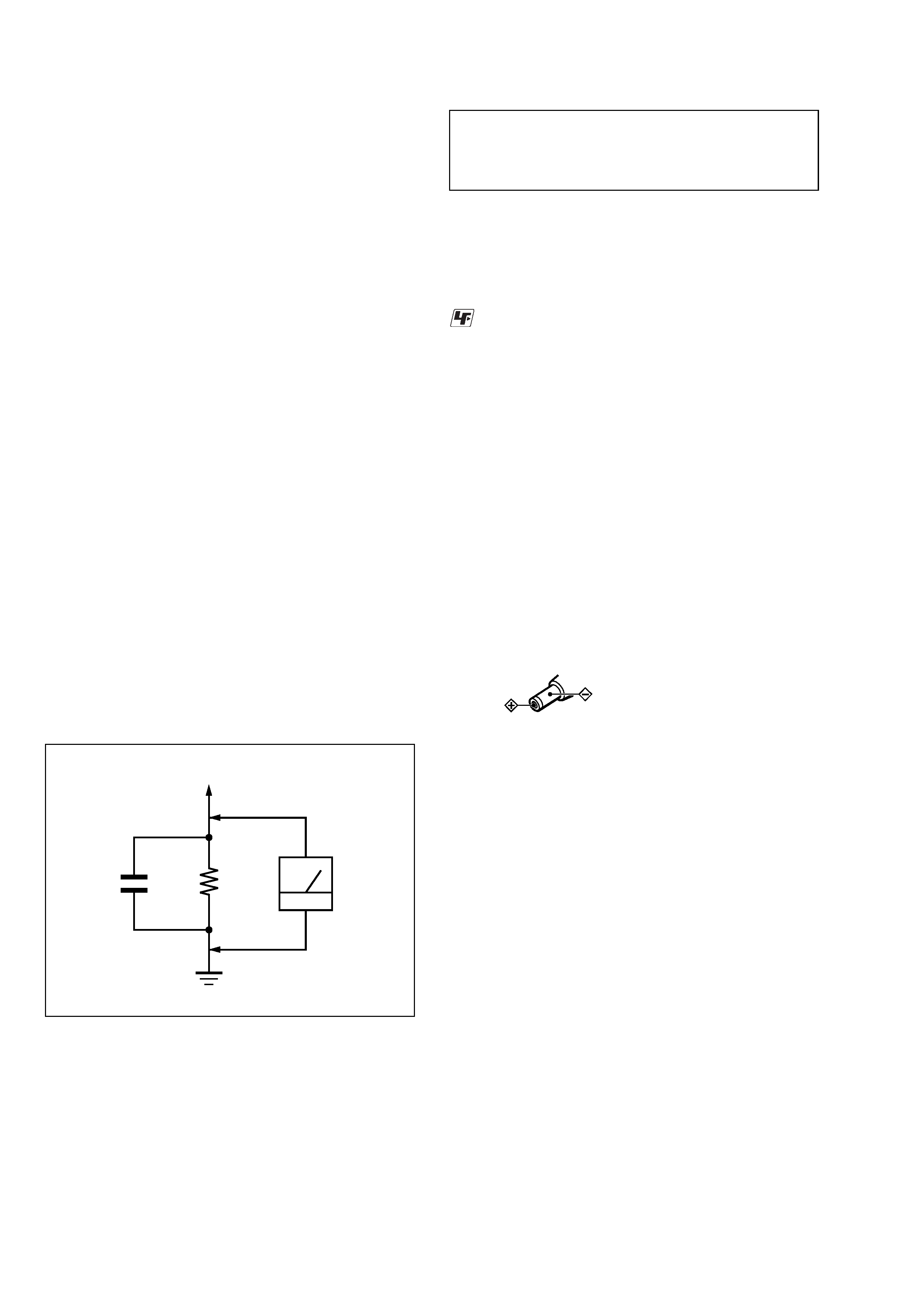
able. (See Fig. A)
Fig. A.
Using an AC voltmeter to check AC leakage.
1.5 k
0.15 µF
AC
voltmeter
(0.75 V)
To Exposed Metal
Parts on Set
Earth Ground
UNLEADED SOLDER
Boards requiring use of unleaded solder are printed with the lead-
free mark (LF) indicating the solder contains no lead.
(Caution: Some printed circuit boards may not come printed with
the lead free mark due to their particular size)
: LEAD FREE MARK
Unleaded solder has the following characteristics.
· Unleaded solder melts at a temperature about 40 °C higher than
ordinary solder.
Ordinary soldering irons can be used but the iron tip has to be
applied to the solder joint for a slightly longer time.
Soldering irons using a temperature regulator should be set to
about 350 °C.
Caution: The printed pattern (copper foil) may peel away if the
heated tip is applied for too long, so be careful!
· Strong viscosity
Unleaded solder is more viscou-s (sticky, less prone to flow)
than ordinary solder so use caution not to let solder bridges oc-
cur such as on IC pins, etc.
· Usable with ordinary solder
It is best to use only unleaded solder but unleaded solder may
also be added to ordinary solder.
On power sources
· For AC operation, use the supplied AC
power adaptor; do not use any other type.
Polarity of the plug
· The player is not disconnected from the
AC power source (mains) as long as it is
connected to the wall outlet, even if the
player itself has been turned off.
· Unplug the player from the wall outlet
when it is not be used for an extended
period of time.
· When the batteries are not to be used,
remove them to avoid damage that can be
caused by battery leakage or corrosion.
· The nameplate indicating operating
voltage, etc. is located at the rear.
About CD-Rs/CD-RWs
This player can play CD-Rs/CD-RWs
recorded in the CD-DA format*, but
playback capability may vary depending on
the quality of the disc and the condition of
the recording device.
* CD-DA is the abbreviation for Compact
Disc Digital Audio. It is a recording
standard used for Audio CDs.
3
ZS-D10
S895
TABLE OF CONTENTS
1.
SERVICING NOTES ..............................................
3
2.
GENERAL ..................................................................
4
3.
DISASSEMBLY
3-1. Disassembly Flow ...........................................................
5
3-2. Net Sub Assy ...................................................................
6
3-3. Cover (CD) Assy .............................................................
6
3-4. LCD Assy ........................................................................
7
3-5. Optical Block (KSM-900AAA), RELAY Board ............
7
3-6. Optical Pick-up (KSS-900A) ..........................................
8
3-7. Cabinet (Rear) Assy ........................................................
8
3-8. Speaker (8cm) (Lch/Rch) ................................................
9
3-9. TUNER Board ................................................................. 10
3-10. Chassis Section ............................................................... 10
3-11. DOOR SW Board, MAIN Board .................................... 11
4.
ASSEMBLY
4-1. Assembly Flow ................................................................ 12
4-2. CD Lid Assy, Spring (T) ................................................. 13
4-3. Cover (CD) Sub Assy, Spring (U) and Collar ................ 13
4-4. How to install the CD lid assy ........................................ 14
4-5. Gear ................................................................................. 15
4-6. Damper ............................................................................ 15
5.
ELECTRICAL ADJUSTMENTS
Tuner Section ................................................................. 16
CD Section ..................................................................... 17
6.
DIAGRAMS
6-1. Block Diagram CD Section .................................... 18
6-2. Block Diagram TUNER Section ............................ 19
6-3. Block Diagram MAIN Section ............................... 20
6-4. Note for Printed Wiring Boards and
Schematic Diagrams ....................................................... 21
6-5. Printed Wiring Boards CD Section ........................ 22
6-6. Schematic Diagram CD Section ............................. 23
6-7. Printed Wiring Board
TUNER Section (US, Canadian Models) ................ 24
6-8. Schematic Diagram
TUNER Section (US, Canadian Models) ................ 25
6-9. Printed Wiring Board TUNER Section
(AEP, UK, Italian, East European Models) ................ 26
6-10. Schematic Diagram TUNER Section
(AEP, UK, Italian, East European Models) ................ 27
6-11. Schematic Diagram CONTROL/PANEL Section .. 28
6-12. Schematic Diagram
AUDIO/POWER SUPPLY Section ......................... 29
6-13. Printed Wiring Board MAIN Section ..................... 30
6-14. Printed Wiring Boards PANEL Section ................. 31
6-15. Printed Wiring Boards
AUDIO/POWER SUPPLY Section ......................... 32
6-16. IC Pin Function Description .......................................... 37
7.
EXPLODED VIEWS
7-1. Net Sub Assy Section ...................................................... 39
7-2. Cover (CD) Section ......................................................... 40
7-3. Cabinet (Rear) Section .................................................... 41
7-4. Cabinet (Front) Section-1 ............................................... 42
7-5. Cabinet (Front) Section-2 ............................................... 43
7-6. Cabinet (Front) Section-3 ............................................... 44
7-7. Cabinet (Front) Section-4 ............................................... 45
7-8. Cabinet (Front) Section-5 ............................................... 46
7-9
Optical Pick-up Section (KSM-900AAA) ..................... 47
8.
ELECTRICAL PARTS LIST .............................. 48
SECTION 1
SERVICING NOTES
The laser diode in the optical pick-up block may suffer electro-
static break-down because of the potential difference generated
by the charged electrostatic load, etc. on clothing and the human
body.
During repair, pay attention to electrostatic break-down and also
use the procedure in the printed matter which is included in the
repair parts.
The flexible board is easily damaged and should be handled with
care.
NOTES ON LASER DIODE EMISSION CHECK
The laser beam on this model is concentrated so as to be focused
on the disc reflective surface by the objective lens in the optical
pick-up block. Therefore, when checking the laser diode emis-
sion, observe from more than 30 cm away from the objective lens.
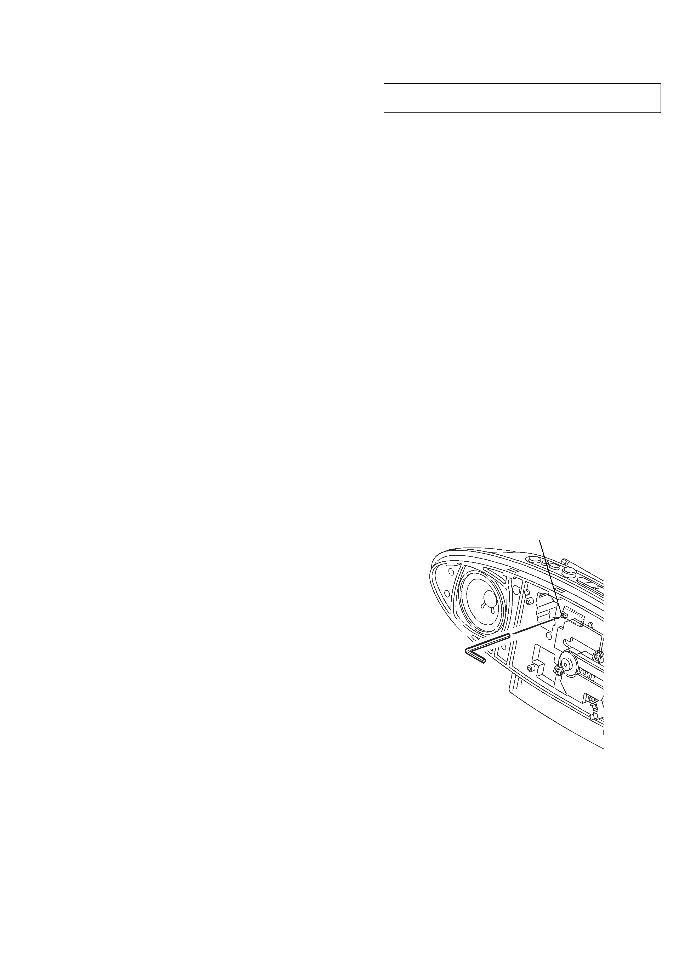
LASER DIODE AND FOCUS SEARCH OPERATION
CHECK
During normal operation of the equipment, emission of the laser
diode is prohibited unless the lid is closed while turning ON the
S895. (push switch type)
The following checking method for the laser diode is operable.
· Method (In the normal operation)
Emission of the laser diode is visually checked.
1. Open the lid.
2. Push the S895 as shown in Fig.1.
3. Check the object lens for confirming normal emission of the
laser diode. If not emitting, there is a trouble in the automatic
power control circuit or the optical pick-up.
In this operation, the object lens will move up and down 2
times along for the focus search.
NOTES ON HANDLING THE OPTICAL PICK-UP
BLOCK OR BASE UNIT
Fig.1 Method to push the S895
4
ZS-D10
SECTION 2
GENERAL
This section is extracted from
instruction manual.
To turn on/off the power
Press POWER. (US, CND models)
Press OPERATE. (AEP, UK, IT, EE models)
· Abbreviation
CND: Canadian model
EE
: East European model
IT
: Italian model
To adjust the volume
Press VOLUME +, (VOL +, on the remote).
To listen through headphones
Connect the headphones to the i (headphones) jack.
To turn off the blue light of the CD compartment lid
When the player is turned on, the blue light of the CD compartment lid lights. To turn the light
off, press and hold MODE for about 4 seconds.
To turn the light on again, press and hold MODE for about 4 seconds.
Adjusting the audio emphasis
You can adjust the audio emphasis of the sound you are listening to.
To reinforce the bass sound
Press MEGA BASS.
"MEGA BASS" appears in the display.
To return to normal sound, press the button again.
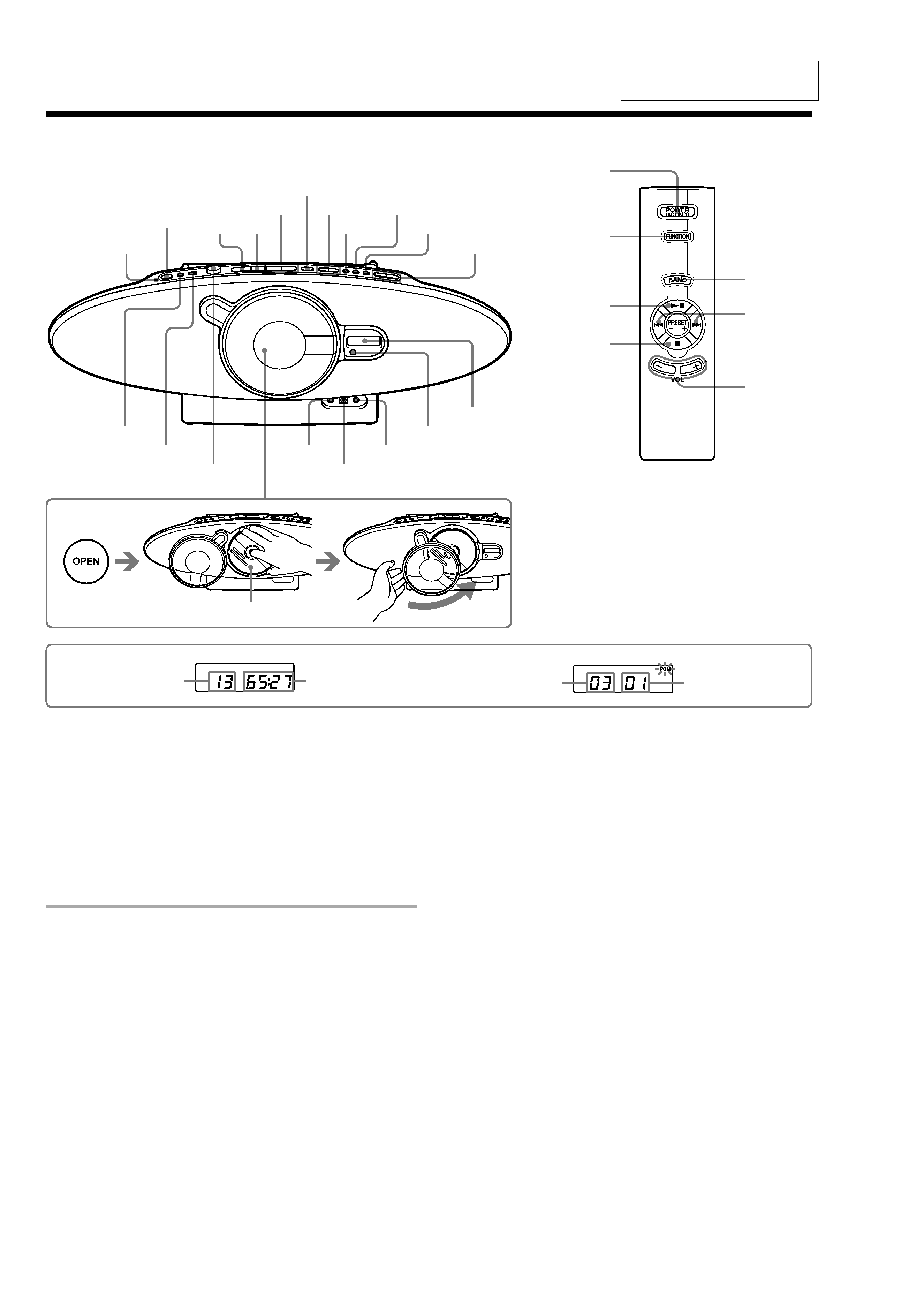
Total track number
Programmed track
Playing order
C
D
Total playing time
Display
Location of controls
Remote Control
FUNCTION
BAND
POWER
(US, CND models)
OPERATE
(AEP, UK, IT, EE models)
VOL +*,
x
PRESET +,
.
,>
SLEEP
*The button has a tactile dot.
POWER
(US, CND models)
OPERATE
(AEP, UK, IT, EE models)
LINE
OPEN
LINE IN
OPTICAL DIGITAL OUT (CD)
TUNE , +
MODE
x
u
*
RADIO
BAND
AUTO PRESET
Display
Remote sensor
.
, >
PRESET , +
VOLUME , +*
MEMORY
DISPLAY
ENTER
MEGA BASS
OPERATION indicator
Loading a CD
With the labeled side facing you
i
u
ZS-D10
5
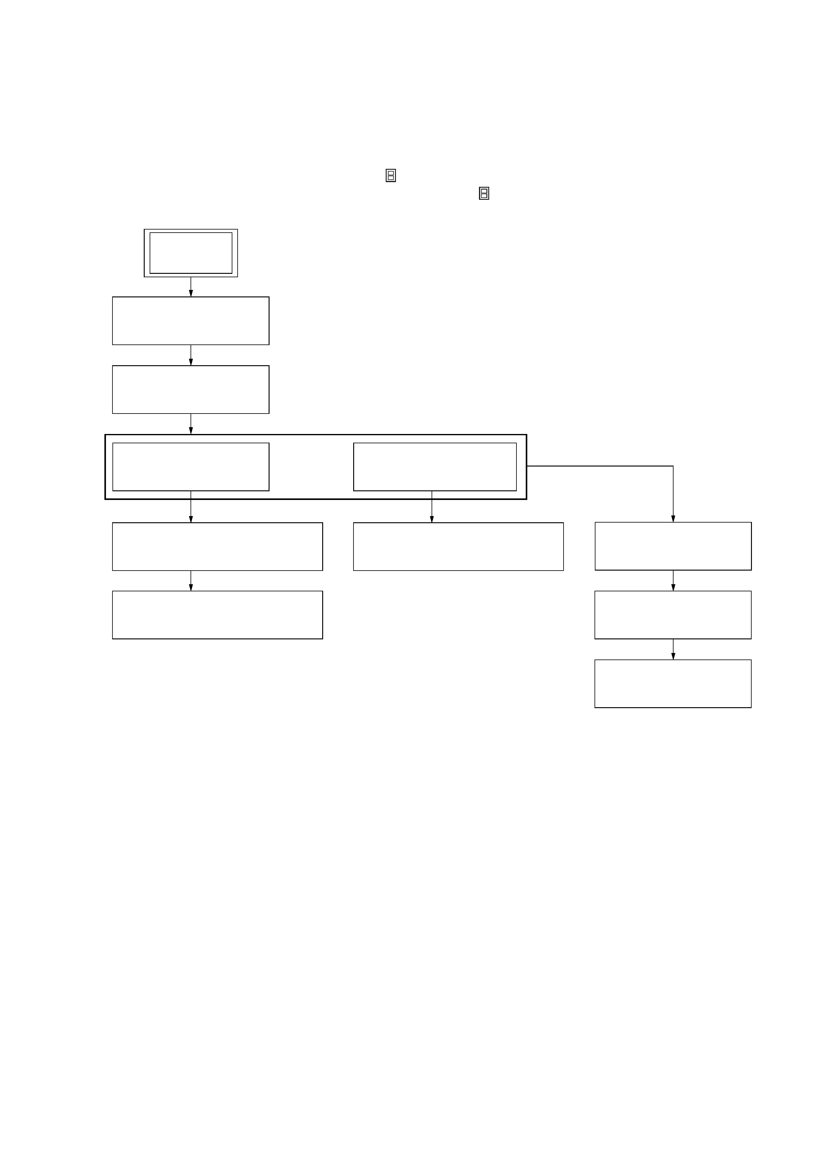
· This set can be disassembled in the order shown below.
3-1.
DISASSEMBLY FLOW
SECTION 3
DISASSEMBLY
3-2. NET SUB ASSY
(Page 6)
3-3. COVER (CD) ASSY
(Page 6)
3-5. OPTICAL BLOCK (KSM-900AAA)
RELAY BOARD
(Page 7)
3-6. OPTICAL PICKP-UP (KSS-900A)
(Page 8)
3-10. CHASSIS SECTION
(Page 10)
3-11. MAIN BOARD
(Page 11)
3-4. LCD ASSY
(Page 7)
3-8. SPEAKER (8 cm) (Lch/Rch)
(Page 9)
3-7. CABINET (REAR) ASSY
(Page 8)
3-9. TUNER BOARD
(Page 10)
SET
Note 1: The process described in
can be performed in any order.
Note 2: Without completing the process described in
, the next process can not be performed.