1
SERVICE MANUAL
US Model
XVM-H6
· This set consists of the following units.
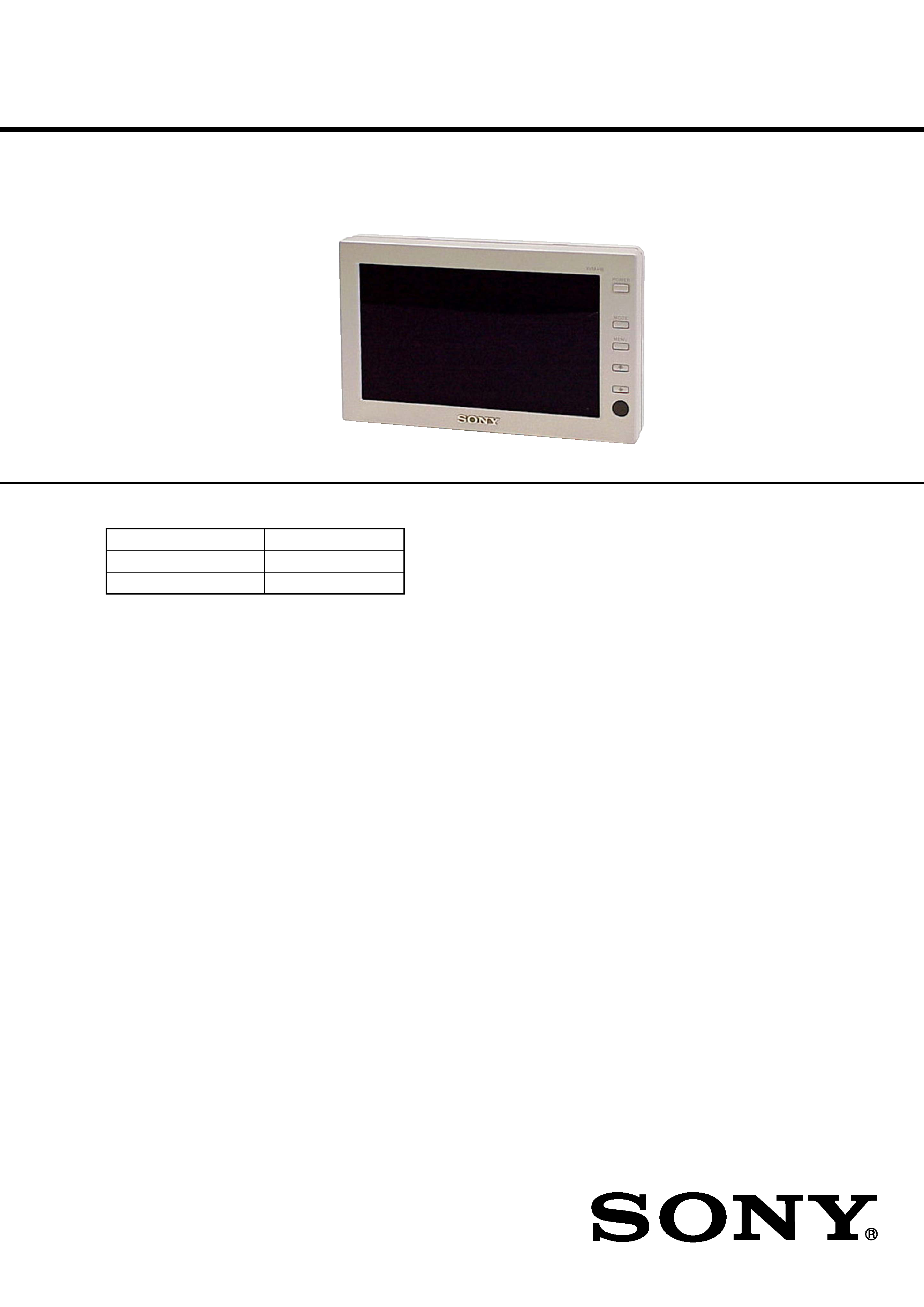
MONITOR
XVM-H6D
CONNECTION BOX
XA-116
REMOTE COMMANDER
RM-X125
SPECIFICATIONS
Monitor
System
Liquid crystal color display
Drive system
TFT-LCD active matrix
system
Picture size
5.8 inches wide screen (16:9)
124
× 73 mm, 147 mm
(5
× 2 7/8 in., 5 7/8 in.)
(w/h, d)
Picture segment
280,800 (w 1200
× h 234) dots
Power requirements
12 V DC car battery
(negative ground)
Current drain
Approx. 600 mA
Dimensions
160
× 98 × 30 mm
(6 3/8
× 3 7/8 × 1 1/8 in.)
(w/h/d)
Operating temperature
5 °C 45 °C
(41 °F 113 °F)
Mass
Approx. 300 g (11 oz)
Connection box XA-116
Video Output
Video:
75
1Vp-p
Video Input
× 2 (Input-A, Input-B)
Video:
75
1 Vp-p
Dimensions
92
× 29 × 62 mm
(3 5/8
× 1 3/16 × 2 1/2 in.)
(w/h/d)
Mass
Approx. 100 g (4 oz)
Card remote commander RM-X125
Power requirements
CR2025 lithium battery
Operable range
Approx. 2.5 m (8.22 ft.)
Dimensions
56
× 89 × 7 mm
(2 1/4
× 3 5/8 × 9/32 in.)
(w/h/d)
Mass
Approx. 25 g (1 oz)
(including batteries)
Supplied accessories
Connection box XA-116 (1)
Card remote commander RM-X125
(with supplied battery) (1)
Power supply cord (1)
Extension cable (5 m) (1)
Mounting plate (1)
Collar (1)
Screws (4)
Operating Instructions (1)
Design and specifications are subject to change
without notice.
Ver 1.0 2002. 07
9-874-136-01
2002G0400-1
© 2002. 07
HEADREST MONITOR
Sony Corporation
e Vehicle Company
Published by Sony Engineering Corporation

2
TABLE OF CONTENTS
1. GENERAL
Location of Controls ............................................................... 3
Connection diagram ............................................................... 5
2. DISASSEMBLY
2-1. Bottom Cabinet .................................................................. 6
2-2. Display Board .................................................................... 7
2-3. Liquid Crystal Display Panel (LCD1) ............................... 7
3. ELECTRICAL ADJUSTMENTS
3-1. Equipment Used ................................................................. 8
3-2. Connection of Equipment .................................................. 8
3-3. 5V Adjustment ................................................................... 8
3-4. Frequency Adjustment ....................................................... 8
3-5. PLL Free Run Frequency Adjustment ............................... 8
3-6. Brightness Temporary Level Adjustment ........................... 9
3-7. Sharpness Adjustment ........................................................ 9
3-8. Contrast Adjustment ........................................................... 9
3-9. Color Adjustment ............................................................... 9
3-10. Hue Adjustment ................................................................. 9
3-11.
2 Adjustment .................................................................... 9
3-12.
0 Adjustment .................................................................... 9
3-13. RGB Gain (1) Adjustment ................................................. 9
3-14. RGB Gain (2) Adjustment ................................................. 9
3-15. B and R Level Adjustments ................................................ 9
3-16. VCOM AMP Adjustment ................................................... 9
3-17. VCOM Bias Adjustment .................................................. 10
3-18. Blank Level Adjustment ................................................... 10
4. DIAGRAMS
4-1. Block Diagram Video Section ...................................... 11
4-2. Block Diagram Display Section ................................... 12
4-3. Printed Wiring Board Display Section (1/2) ................ 14
4-4. Printed Wiring Board Display Section (2/2) ................ 15
4-5. Schematic Diagram Display Section (1/3) ................... 16
4-6. Schematic Diagram Display Section (2/3) ................... 17
4-7. Schematic Diagram Display Section (3/3) ................... 18
4-8. IC Block Diagrams .......................................................... 19
5. EXPLODED VIEW
5-1. Main Section .................................................................... 23
6. ELECTRICAL PARTS LIST ....................................... 24
Notes on Chip Component Replacement
·Never reuse a disconnected chip component.
· Notice that the minus side of a tantalum capacitor may be
damaged by heat.
XVM-H6
SAFETY-RELATED COMPONENT WARNING!!
COMPONENTS IDENTIFIED BY MARK 0 OR DOTTED LINE
WITH MARK 0 ON THE SCHEMATIC DIAGRAMS AND IN
THE PARTS LIST ARE CRITICAL TO SAFE OPERATION.
REPLACE THESE COMPONENTS WITH SONY PARTS WHOSE
PART NUMBERS APPEAR AS SHOWN IN THIS MANUAL OR
IN SUPPLEMENTS PUBLISHED BY SONY.
3
XVM-H6
SECTION 1
GENERAL
This section is extracted
from instruction manual.
6
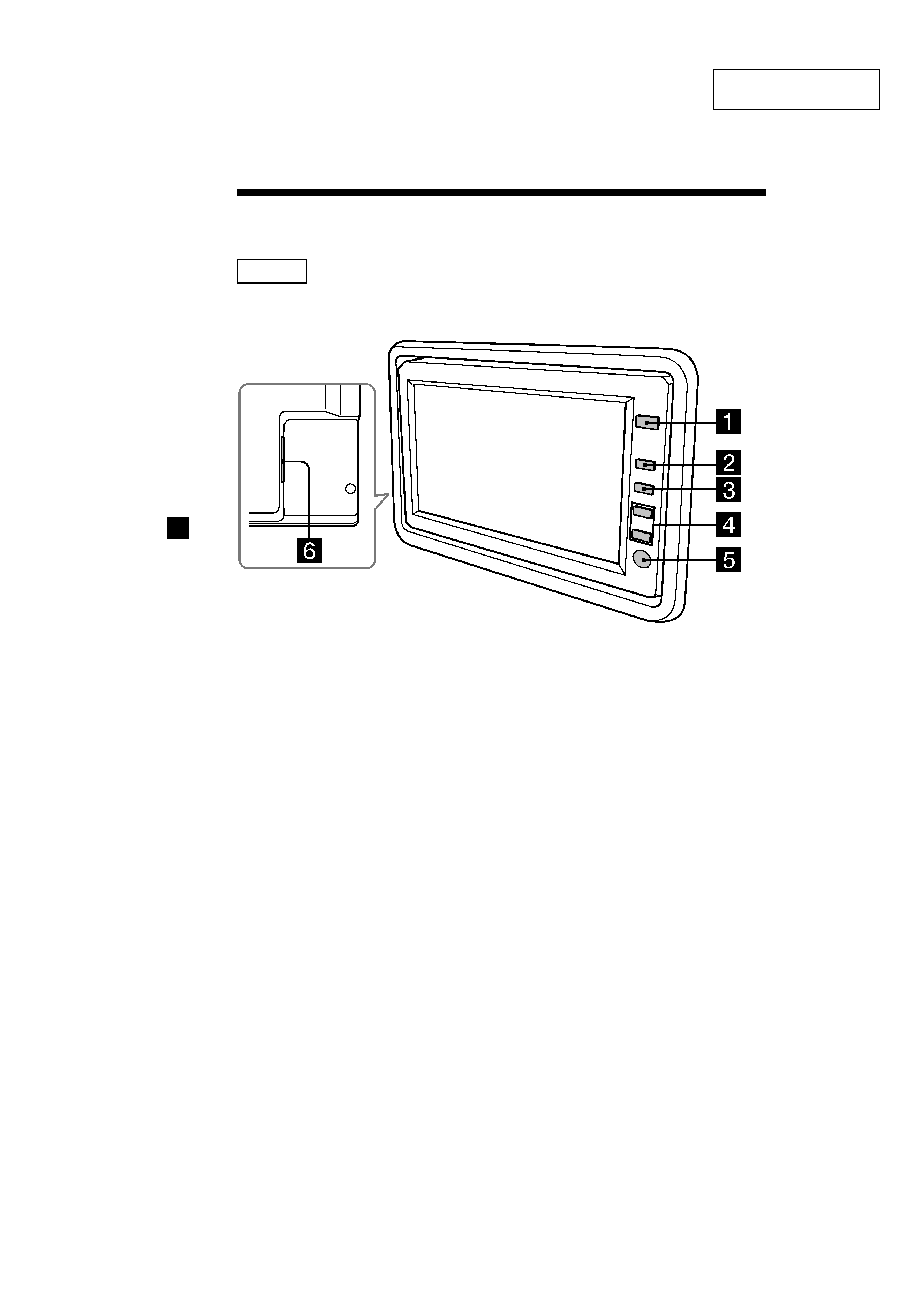
Location of Controls
1 POWER button 8
2 INPUT button 8
Press to select the input source.
3 MENU button 10
Press to adjust the various display
settings.
4 F/f buttons 8, 10
5 Receptor for the card remote
commander
6 Monitor connector
Monitor
4
XVM-H6
7
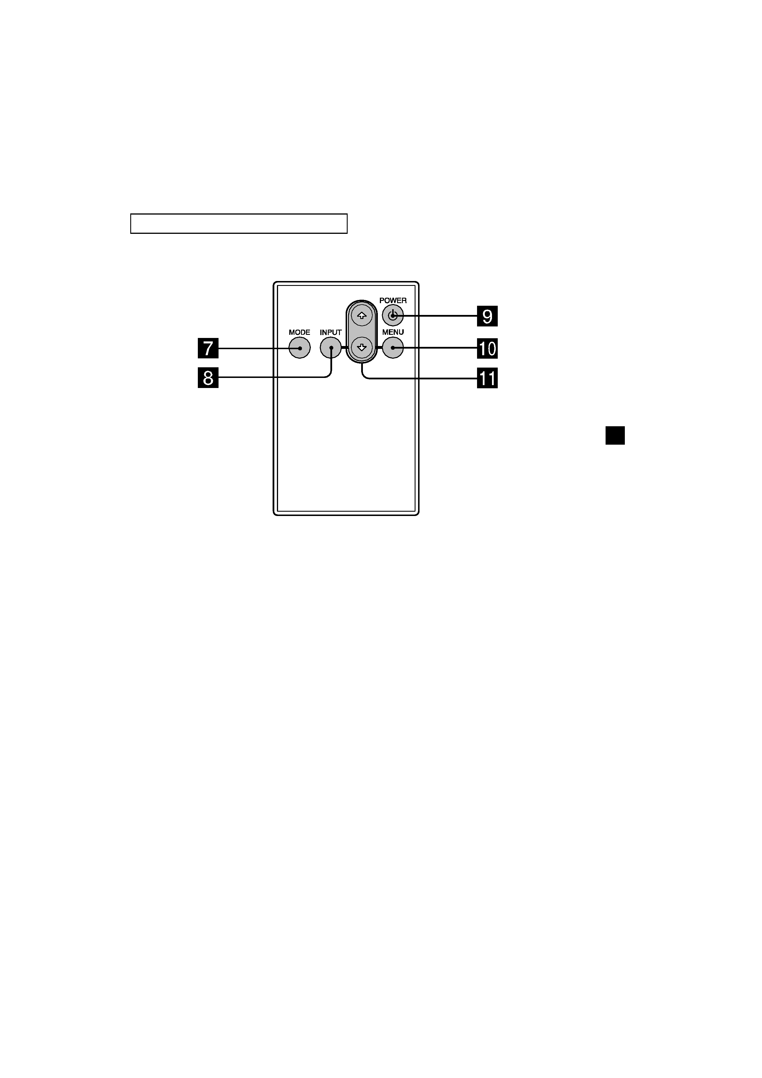
Tip
Refer to "Replacing the lithium battery" for details on how to replace the batteries (page
15).
7 MODE button 9
Press to change the screen mode.
8 INPUT button 8
Press to select the input source.
9 POWER button 8
Card remote commander RM-X125
0 MENU button 10
Press to adjust the various display
settings.
qa F/f buttons 8, 10
5
XVM-H6
13
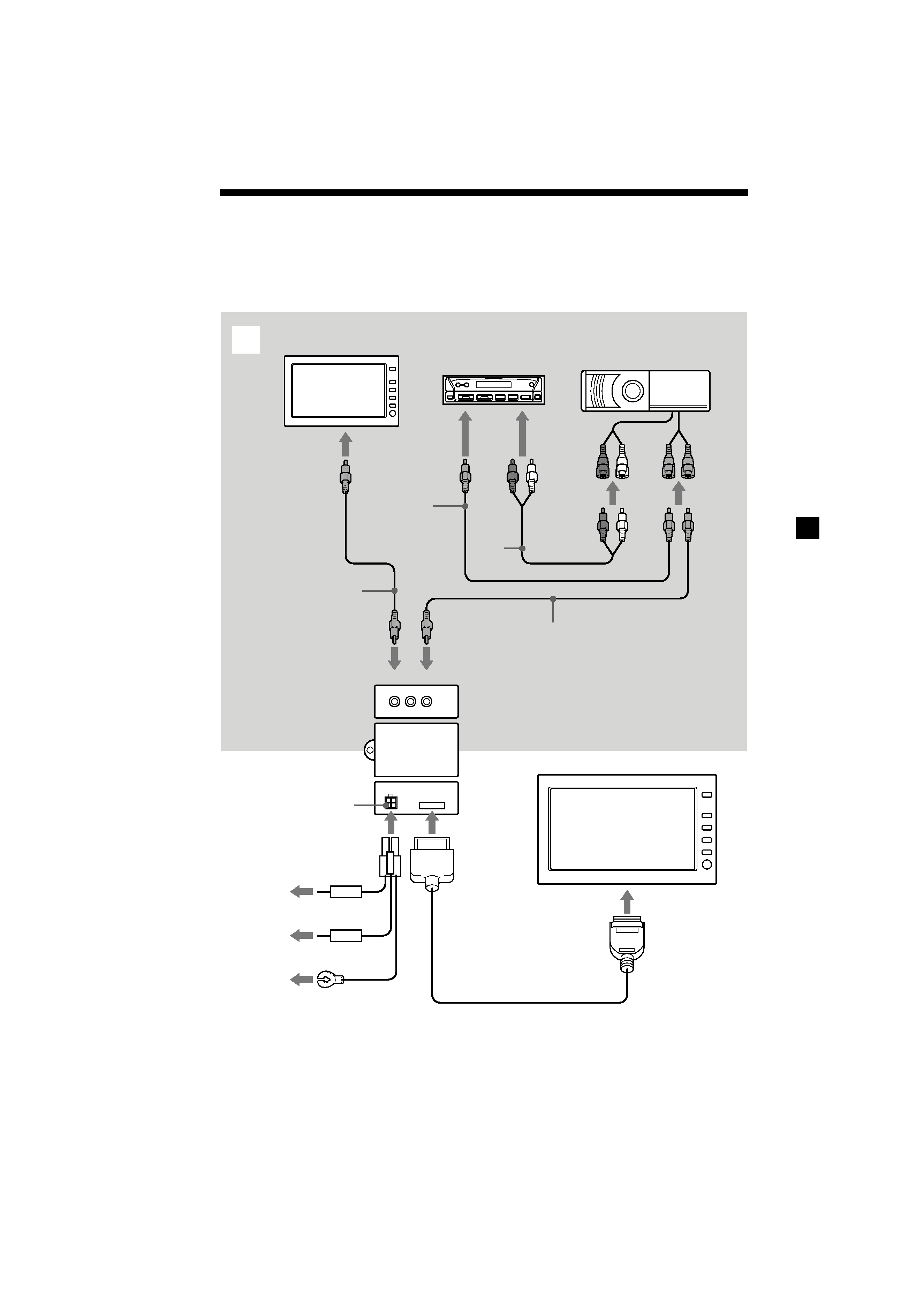
Connection diagram
Standard connections
Refer to the diagram for the proper connections.
You can make connections shown in A area. Please ask a qualified technician for the
other connections.
To additional monitor
(OUT) (optional)
Rear
Headrest Monitor
*1 DVD Changer DVX-
100 (optional)
OUT
IN
Connection Box
XA-116
Front
Extension cable (5 m)
4 Pin Power
connector
Fuse 0.1 A
Fuse 3 A
(Yellow) (5 m)
(Blue) (1 m)
(Red) (5 m)
To a metal
surface of the
car chassis
To car battery
(12 V)
To ignition
switch
(ACC position)
Media Center/FM/AM
Receiver XAV-7W
(optional)
A
Power supply cord
To Video input
To Video output
To Audio
input L/R
*1 Video signals of DVX-100 are
output to XVM-H6, and audio
signals are output to XAV-7W.
*2 RCA pin cord (optional)
To Video
output
To Video
input
To Video input
To Audio
output L/R
*2
*2
*2
*2