SERVICE MANUAL
MOBILE TV TUNER
US Model
Canadian Model
E Model
Australian Model
Chinese Model
Russian Model
SPECIFICATIONS
XT-V70
Ver. 1.0 2005.09
9-879-878-01
2005I05-1
© 2005.09
Sony Corporation
e Vehicle Company
Published by Sony Engineering Corporation
Reception format
US, Canadian, E (NTSC) models:
NTSC
Russian model: SECAM
E (PAL), Australian, Chinese models:
PAL
Channels
US, Canadian, E (NTSC) models:
2-13 (VHF)
14-69 (UHF)
Russian model:
1-12 (VHF)
21-69 (UHF)
E (PAL) model:
2-12 (VHF)
21-69 (UHF)
Australian model:
0-12 (VHF)
28-69 (UHF)
(Monaural)
Chinese model:
1-12 (VHF)
13-57 (UHF)
Power requirement
12 V DC
(negative ground)
Power consumption 240 mA
Inputs
Video (1)
Bus (1)
TV antenna (4)
Outputs
Video (1)
Bus (1)
Dimensions
Approx. 127
× 30 × 107 mm
(5
× 1 3/16 × 4 1/4 in.)
(W
× H × D)
Mass
Approx. 0.38 kg (13 oz)
Design and specifications are subject to change without notice.
· This set is mobile TV tuner for XAV-A1 use only.
· This set includes the TV antenna (VCA-119).

2
XT-V70
1.
SERVICING NOTES ................................................ 3
2.
GENERAL ................................................................... 4
3.
ELECTRICAL ADJUSTMENTS .......................... 7
4.
DIAGRAMS
4-1.
Block Diagram (Except Russian model) .........................
9
4-2.
Block Diagram (Russian model only) ............................. 10
4-3.
Printed Wiring Boards TV Section (1/2)
(Except Russian model) ................................................... 12
4-4.
Printed Wiring Board TV Section (2/2)
(Except Russian model) ................................................... 13
4-5.
Schematic Diagram TV Section
(Except Russian model) ................................................... 14
Notes on chip component replacement
· Never reuse a disconnected chip component.
· Notice that the minus side of a tantalum capacitor may be
damaged by heat.
Flexible Circuit Board Repairing
· Keep the temperature of the soldering iron around 270 °C
during repairing.
· Do not touch the soldering iron on the same conductor of the
circuit board (within 3 times).
· Be careful not to apply force on the conductor when soldering
or unsoldering.
UNLEADED SOLDER
Boards requiring use of unleaded solder are printed with the lead-
free mark (LF) indicating the solder contains no lead.
(Caution: Some printed circuit boards may not come printed with
the lead free mark due to their particular size)
: LEAD FREE MARK
Unleaded solder has the following characteristics.
· Unleaded solder melts at a temperature about 40 °C higher
than ordinary solder.
Ordinary soldering irons can be used but the iron tip has to be
applied to the solder joint for a slightly longer time.
Soldering irons using a temperature regulator should be set to
about 350
°C.
Caution: The printed pattern (copper foil) may peel away if
the heated tip is applied for too long, so be careful!
· Strong viscosity
Unleaded solder is more viscou-s (sticky, less prone to flow)
than ordinary solder so use caution not to let solder bridges
occur such as on IC pins, etc.
· Usable with ordinary solder
It is best to use only unleaded solder but unleaded solder may
also be added to ordinary solder.
4-6.
Schematic Diagram TV Section (1/3)
(Russian model only) ...................................................... 15
4-7.
Schematic Diagram TV Section (2/3)
(Russian model only) ....................................................... 16
4-8.
Schematic Diagram TV Section (3/3)
(Russian model only) ...................................................... 17
4-9.
Printed Wiring Boards TV Section (1/2)
(Russian model only) ....................................................... 18
4-10. Printed Wiring Board TV Section (2/2)
(Russian model only) ....................................................... 19
5.
EXPLODED VIEW ................................................... 27
6.
ELECTRICAL PARTS LIST ................................ 28
TABLE OF CONTENTS
3
XT-V70
SECTION 1
SERVICING NOTES
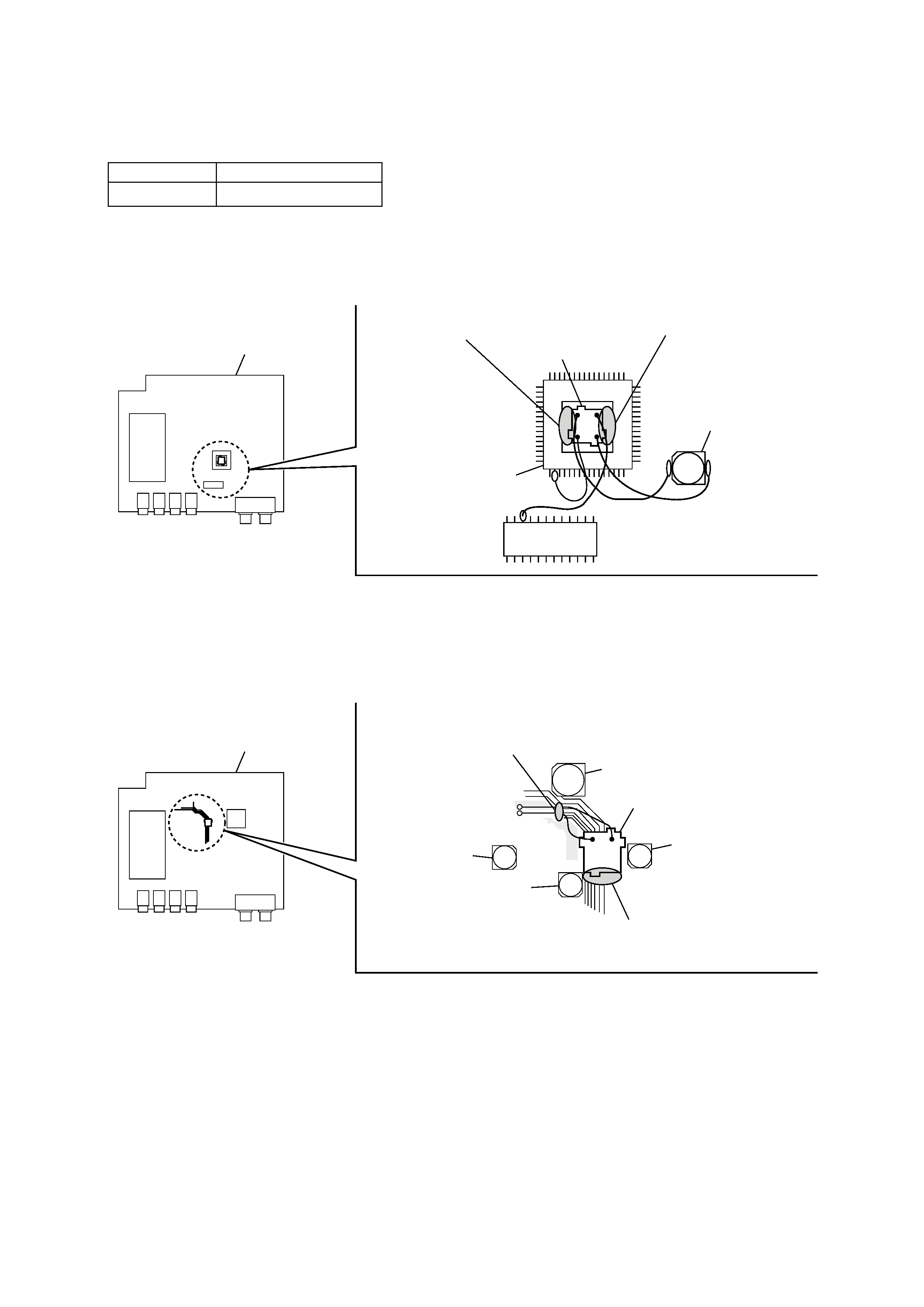
IC301
TV board
SYNC board
SYNC board (Russian model)
TV2 board (except Russian model)
If replacing the SYNC board, disconnect the SYNC board from the TV board,
and clear off the remaining bond with a cutter, etc. and then apply the bond and install new board.
In clearing off the remaining bond with a cutter, take care not to damage the board or mounted parts.
If replacing the TV2 board, disconnect the TV2 board from the TV board,
and clear off the remaining bond with a cutter, etc. and then apply the bond and install new board.
In clearing off the remaining bond with a cutter, take care not to damage the board or mounted parts.
To secure the SYNC/TV2 boards, a special bond is required.
Part. No.
Description
7-432-912-48
SONY BOND SC608LV
C330
C105
C153
C6
C47
IC403
TV board
TV2 board
For the bond application locations.
(SONY BOND SC608LV)
For the bond application locations.
(SONY BOND SC608LV)
For the bond application locations.
(SONY BOND SC608LV)
For the bond application locations.
(SONY BOND SC608LV)
NOTES ON REPLACEMENT OF SYNC/TV2 BOARDS
4
XT-V70
SECTION 2
GENERAL
This section is extracted from
instruction manual.
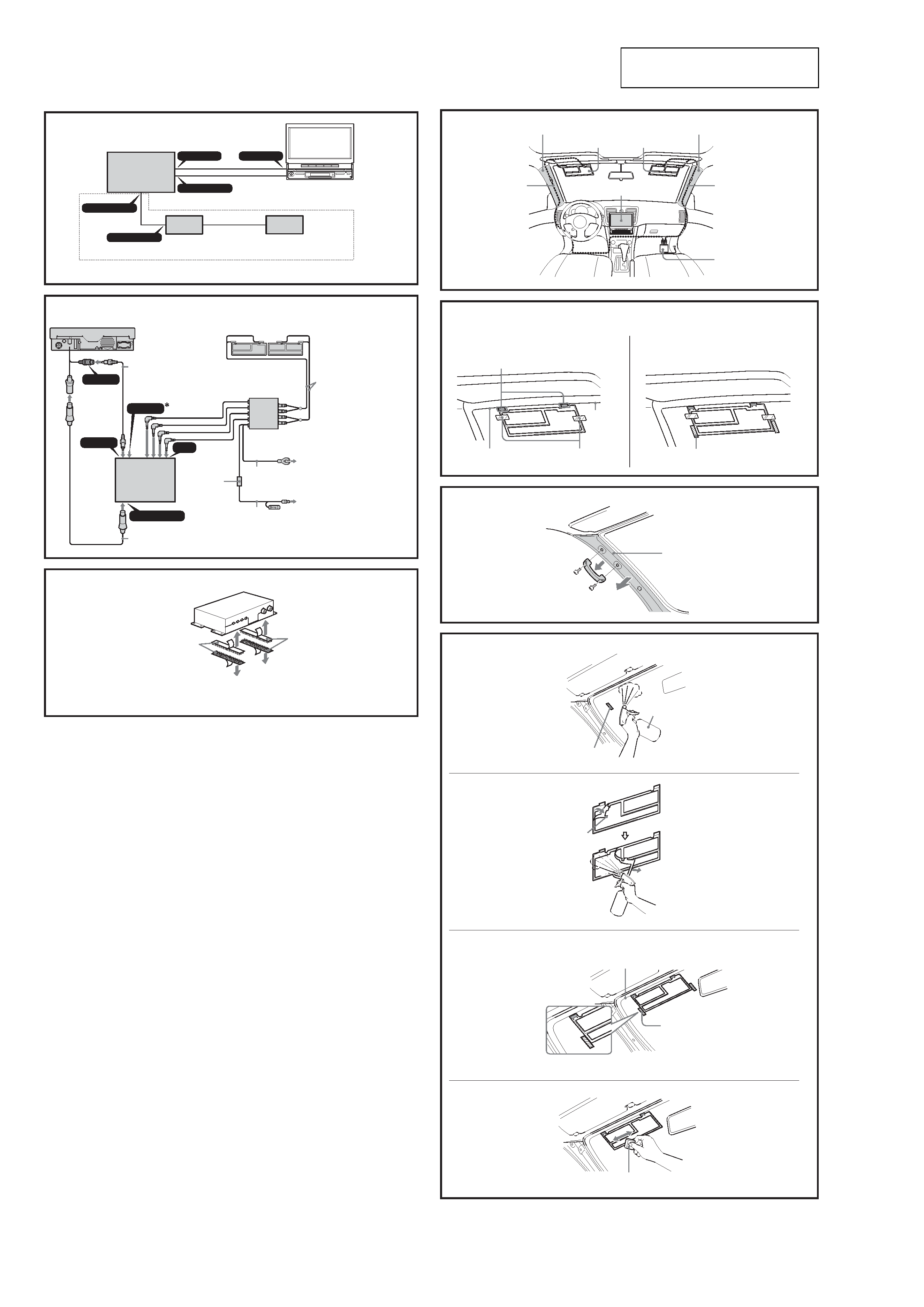
3
CONTROL OUT
AUX 3
CONTROL OUT
CONTROL IN
VIDEO OUT
AV Center
AV Center
XAV-A1
TV tuner unit
Tuner de télévision
XT-V70
Connection box XA-123
(supplied with XAV-A1)
Boite de raccordement XA-123
(fournie avec XAV-A1)
XM radio tuner (optional)
XM tuner de radio (en option)
AUX 3
VIDEO OUT
VIDEO IN
ANT IN
CONTROL OUT
AV Center
AV Center
XAV-A1
Film antenna
5
Antenne film
5
RCA interconnects (5 m)
2
Interconnexions RCA (5 m)
2
TV antenna amplifier unit
4
Amplificateur d'antenne de télévision
4
Antenna input cable
6
Câble d'entrée d'antenne
6
TV tuner unit
Tuner de télévision
XT-V70
Black
Noir
Bus cable (5.3 m)
1
Câble de bus (5,3 m)
1
To a metal surface of the car
A la surface métallique de la voiture
Red
Rouge
To the +12 V power terminal which is
energized in the accessory position of the
ignition key switch.
Be sure to connect the black ground lead to
it first.
A la borne d'alimentation +12 V traversee
par le courant a la position accessoire de la
cle de contact.
Raccordez-y bien le fil de mise a la terre noir
en premier.
2
4
Hook-and-loop fastener
3
Patins adhésifs
3
On installation surface
Sur la surface d'installation
Hook-and-loop fastener
3
Patins adhésifs
3
XT-V70
Fuse (0.5 A)
Fusible (0,5 A)
Available only in the USA.
Disponible seulement aux Etats-Unis.
* To the optional back camera or a video
equipment (to AUX 3).
*A une caméra arrière en option ou un
équipement vidéo (à AUX3).
5
6
1
2
Front pillar
Montant avant
Antenna input cable
6
Câble d'entrée d'antenne
6
Film antenna (left)
5
Antenne film (gauche)
5
XAV-A1
Film antenna (right)
5
Antenne film (droite)
5
TV antenna amplifier unit
4
Amplificateur d'antenne de
télévision
4
Antenna input cable
6
Câble d'entrée d'antenne
6
Front pillar
Montant avant
Power supply point
Point d'alimentation
Ceramic line
Ligne en
céramique
Align the upper edge of the
antenna with this line.
Aligner l'extrémité supérieure de
l'antenne sur cette ligne.
Temporary fastener
(cellophane tape, etc.)
Fixation temporaire
(ruban adhésif etc.)
Marking (cellophane tape, etc.)
Marque (ruban adhésif etc.)
7
Front pillar
Montant avant
8
1
Spray bottle
Vaporisateur
Marking (cellophane tape, etc.)
Marque (ruban adhésif etc.)
Peel-off tab
Languette d'écaillage
Align the upper edge of the antenna with this line.
Aligner le bord supérieur de l'antenne sur cette ligne.
Marking (cellophane tape, etc.)
Marque (ruban adhésif etc.)
2
4
3
Squeegee
8
Raclette
8
5
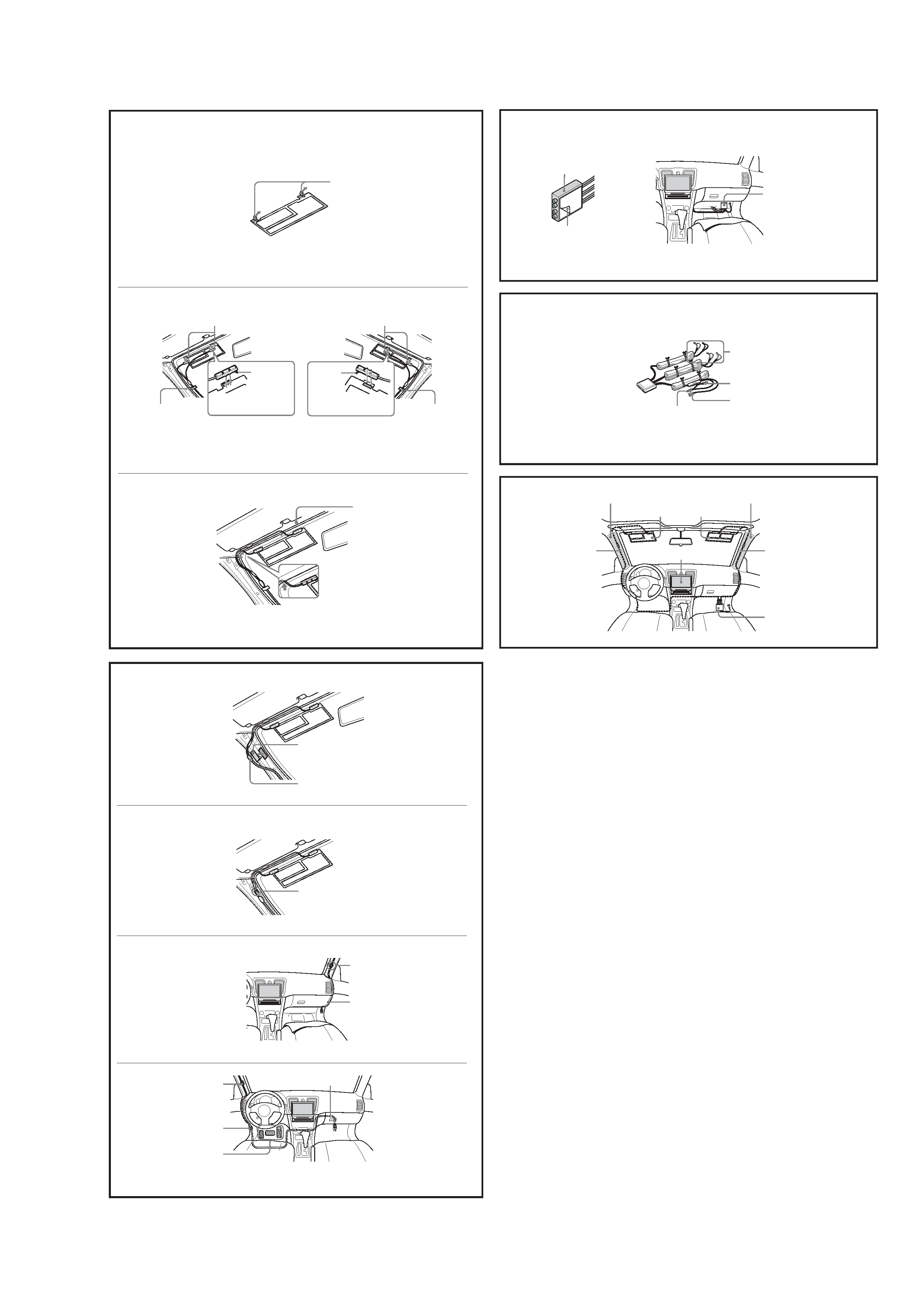
XT-V70
9
q;
1
2
3
Protective sheet
Feuille de protection
Power supply point
Point d'alimentation
Peel off the
protective
sheet.
Détachez la
feuille de
protection.
Temporary fastening
(cellophane tape, etc.)
Fixation temporaire
(ruban adhésif etc.)
Roof lining
Garniture du toit
Power supply point
Point d'alimentation
Peel off the
protective
sheet.
Détachez la
feuille de
protection.
Temporary fastening
(cellophane tape, etc.)
Fixation temporaire
(ruban adhésif etc.)
1
2
4
3
Grounding tape
7 (peel off the protective sheet.)
Ruban de terre
7 (détachez la feuille de protection.)
Ground contact (peel off the protective sheet.)
Contact de terre (détachez la feuille de protection.)
Antenna cord clamp
9
Serre-fils de cordon d'antenne
9
Antenna input cable (right)
6
Câble d'entrée d'antenne (droit)
6
Antenna input cable (left)
6
Câble d'entrée d'antenne (gauche)
6
Antenna cord clamp
9
Serre-fils de cordon d'antenne
9
IMPORTANT CAUTION!
Do not route the cable near the pedals!
PRECAUTION IMPORTANTE!
N'acheminez pas le câble près des pédales!
Antenna cord clamp
9
Serre-fils de cordon
d'antenne
9
Antenna cord clamp
0
Serre-fils de cordon
d'antenne
0
qa
qs
qd
TV antenna amplifier unit
4
Amplificateur d'antenne de téléviseur
4
Peel off the protective sheet.
Détachez la feuille de protection.
Fold back the floor mat.
Retournez le tapis de plancher.
TV antenna amplifier unit
4
Amplificateur d'antenne de téléviseur
4
Antenna contacts
Contacts d'antenne
Spare contact
Contact de rechange
Ground contact
Contact de terre
Vehicle ACC power supply
Alimentation ACC du véhicule
Front pillar
Montant avant
XAV-A1
Film antenna (left)
5
Antenne film (gauche)
5
Film antenna (right)
5
Antenne film (droite)
5
Antenna input cable (right)
6
Câble d'entrée d'antenne (droit)
6
TV antenna amplifier unit
4
Amplificateur d'antenne de
téléviseur
4
Antenna input cable (left)
6
Câble d'entrée d'antenne
(gauche)
6
Front pillar
Montant avant