SERVICE MANUAL
MOBILE TV TUNER
AEP Model
UK Model
E Model
Australian Model
Chinese Model
XT-P50V
Ver 1.0 2002.09
9-874-168-01
Sony Corporation
2002I0500-1
e Vehicle Company
C
2002.09
Published by Sony Engineering Corporation
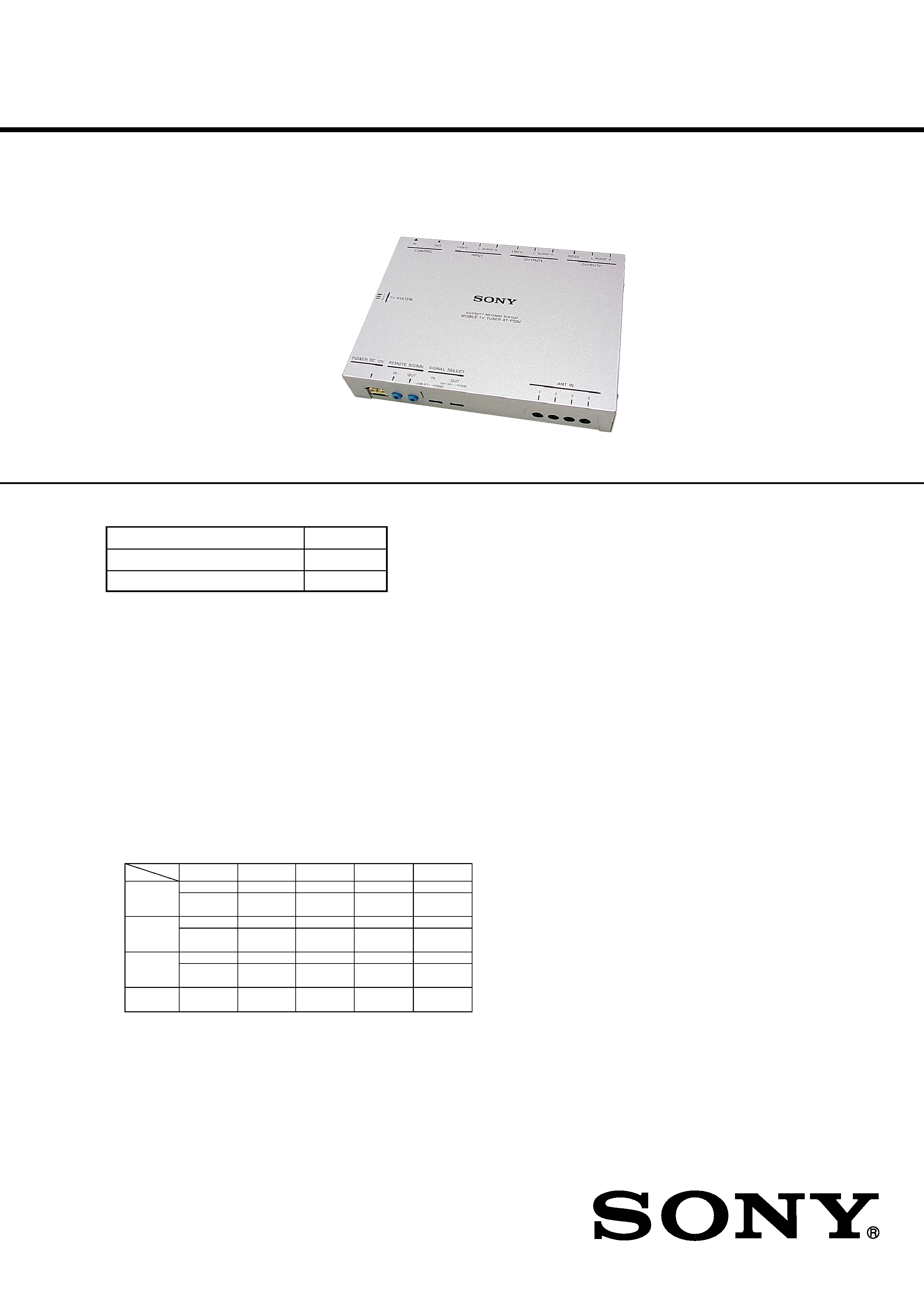
SPECIFICATIONS
The XT-P50V is composed of the following models.
TV tuner unit
XT-P50V
TV Antenna
VCA-116
Wireless Remote Commander
RM-X124
Tuner unit
Reception format
PAL
Power requirements
12 V DC, from car battery
(negative ground)
Power consumption
Approx. 0.5 A
Inputs
Video/audio (Sony BUS compatible)(1)
Sony BUS (1)
TV aerial (4)
Outputs
Video/audio (Sony BUS compatible)(2)
Sony BUS (1)
Dimensions
Approx. 185.5
× 31 × 137 mm
(W
× H × D)
Mass
Approx. 0.7 kg
Channel coverage
Wireless remote commander RM-X124
Power requirements
CR2025 lithium battery
Operable range
Approx. 2.5 m
Dimension
50
× 86 × 11.5 mm (W × H × D)
Mass
Approx. 36 g (including a battery)
Design and specifications are subject to change without notice.
AUSTRALIA
VHF LOW
VHF HIGH
UHF
IF VIDEO
IF AUDIO
0 - 4 CH
5 - 12 CH
28 - 69 CH
38.90 MHz
33.40 MHz
CCIR
2 - 4 CH
5 -12 CH
21 - 69 CH
38.90 MHz
33.40 MHz
48.25 MHz -
62.25 MHz
175.25 MHz -
224.25 MHz
471.25 MHz -
855.25 MHz
UK
21 - 69 CH
38.90 MHz
32.90 MHz
471.25 MHz -
855.25 MHz
CHINA
1 - 5 CH
6 - 12 CH
13 - 57 CH
38.90 MHz
32.40 MHz
49.75 MHz -
85.25 MHz
168.25 MHz -
216.25 MHz
471.25 MHz -
863.25 MHz
ITALY
A - C CH
D - H2 CH
21 - 69 CH
38.90 MHz
33.40 MHz
53.75 MHz -
82.25 MHz
175.25 MHz -
224.25 MHz
471.25 MHz -
855.25 MHz
46.25 MHz -
95.25 MHz
102.25 MHz -
224.25 MHz
527.25 MHz -
814.25 MHz
2
XT-P50V
TABLE OF CONTENTS
1.
GENERAL ................................................................... 2
2.
TEST MODE .............................................................. 5
3.
ELECTRICAL ADJUSTMENTS ......................... 5
4.
DIAGRAMS
4-1. Block Diagram AUDIO Section ...............................
7
4-2. Block Diagram VIDEO Section ...............................
8
4-3. Block Diagram
BUS CONTROL/POWER SUPPLY Section ............
9
4-4. Note for Printed Wiring Board and
Schematic Diagrams ....................................................... 10
4-5. Schematic Diagram HIDEAWAY Board (1/3) ......... 11
4-6. Schematic Diagram HIDEAWAY Board (2/3) ......... 12
4-7. Schematic Diagram HIDEAWAY Board (3/3) ......... 13
4-8. Printed Wiring Board
HIDEAWAY Board (Component Side) ..................... 14
4-9. Printed Wiring Board
HIDEAWAY Board (Conductor Side) ....................... 15
4-10. IC Pin Function Description ........................................... 18
5.
EXPLODED VIEW ................................................... 20
6.
ELECTRICAL PARTS LIST ............................... 21
Notes on chip component replacement
·Never reuse a disconnected chip component.
· Notice that the minus side of a tantalum capacitor may be dam-
aged by heat.
SECTION 1
GENERAL
This section is extracted from
instruction manual.
ANT IN
POWER
DC 12V
OUTPUT
REMOTE
SIGNAL OUT
REMOTE
SIGNAL IN
3
2
DISC
SEEK
SOURCE
MODE
AT T
OFF
OPEN/
CLOSE
.>
VOL
CONTROL OUT
OUTPUT
INPUT
CONTROL IN
Black
Schwarz
XT-P50V
To the +12 V power terminal
which is energized in the
accessory position of the
ignition key switch
an den +12-V-
Stromversorgungsanschluss, an
dem Spannung anliegt, wenn
sich der Zündschlüssel in der
Zubehörposition befindet
To the +12 V power terminal
which is energized at all times
an den +12-V-
Stromversorgungsanschluss, an
dem immer Spannung anliegt
To a metal surface of the car
an eine Metalloberfläche des
Wagens
TV aerial 6
Fernsehantenne 6
Yellow
Gelb
Filter + fuse (5 A)
Filter + Sicherung (5 A)
Power supply leads 1 (5.5 m)
Stromversorgungskabel 1 (5,5 m)
Red
Rot
Fuse (0.5 A)
Sicherung
(0,5 A)
Connection box XA-114
(supplied with XAV-7W)
Anschlussdose XA-114
(mit XAV-7W mitgeliefert)
CD/ MD changer,
or Source selector XA-C30
CD/MD-Wechsler oder
Signalquellenwähler XA-C30
Media Center main unit
XAV-7W
Mediencenter-Hauptgerät
XAV-7W
TV tuner unit
Fernsehtuner
XT-P50V
TV tuner unit
Fernsehtuner
XT-P50V
1
2
Connection box XA-117
(supplied with XVM-R75)
Anschlussdose XA-117
(mit XVM-R75 mitgeliefert)
Overhead monitor
XVM-R75
Deckenmonitor
XVM-R75
DVD changer
DVX-100
DVD-Wechsler
DVX-100
Blue
Blau
6 m
6 m
To the power remote cord (blue)
of the monitor*
(when connected to the monitor)
* If the Sony BUS connection is
used, this connection is not
necessary.
an Stromversorgungskabel (blau)
eines Monitors*
(bei Anschluss an einen Monitor)
* Bei einer Sony-BUS-Verbindung
ist diese Verbindung nicht
erforderlich.
3
XT-P50V
7
1
2
3
8
1
2
Long
Lang
Leave clearance of at least 50 mm.
Mindestens 50 mm Abstand lassen.
Inside of rear window
Innenseite der Heckscheibe
Secure with tape under seat.
Mit Klebeband unter dem Sitz befestigen.
TV tuner unit
XT-P50V
Fernsehtuner
XT-P50V
90
°
90
°
Do not bend sharply.
Nicht scharf knicken.
Bend in a smooth curve.
In einer Rundung biegen.
Leave clearance of at least 50 mm.
Mindestens 50 mm Abstand lassen.
Short
Kurz
Insert between
metal plates.
Zwischen
Metallplatten
einsetzen.
Slide terminal cover forward to
remove.
Anschlussabdeckung zum Abnehmen
nach vorne schieben.
Screw
Schraube
Terminal cover
Anschlussabdeckung
Support clamper 8
Halteklemme 8
Ground plate 7
Masseplatte 7
Bring into contact with metal surface of the car.
Mit Metalloberfläche des Fahrzeugs in Berührung
bringen.
Attach while adjusting angle and
position.
Anbringen, dabei Winkel und Position
einstellen.
Fix support clamper in center of aerial rod.
Halteklemme in der Mitte des Antennenstabs
anbringen.
R
L
V
1
2
REMOTE
COMMANDER
SIGNAL OUT
REMOTE
SIGNAL IN
REMOTE
SIGNAL OUT
SIGNAL SELECT
OUT
DVX-100
OTHERS
IN
XVM-R75
OTHERS
OUTPUT
INPUT
CONTROL
OUT
CONTROL
INPUT
DISC
SEEK
SOURCE
MODE
ATT
OFF
OPEN/
CLOSE
.>
VOL
TV SYSTEM
1
2
3
4
Bus cable 2 (5.3 m)
Buskabel 2 (5,3 m)
RCA interconnects 3 (5.3 m)
Cinch-Verbindungen 3 (5,3 m)
* Connection box
XA-114
(supplied with XAV-7W)
Anschlussdose
XA-114
(mit XAV-7W mitgeliefert)
1
2
XT-P50V
* DVD changer
DVX-100
DVD-Wechsler
DVX-100
* Connection box XA-117
(supplied with XVM-R75)
Anschlussdose XA-117
(mit XVM-R75 mitgeliefert)
RCA interconnects 3 (5.3 m)
Cinch-Verbindungen 3 (5,3 m)
XT-P50V
* Stereo mini plug-to-plug
cable 4 (5 m)
Kabel mit
Stereoministecker-Stecker
4
(5 m)
* Media Center main unit
XAV-7W
Mediencenter-Hauptgerät
XAV-7W
TV SYSTEM switch
Schalter TV SYSTEM
* Monitor
Monitor
SIGNAL SELECT switch
Schalter SIGNAL SELECT
*option
Option
* RCA interconnects
Cinch-Verbindungen
* (5 m)
6
Inside of rear window
Innenseite der Heckscheibe
Inside of rear window
Innenseite der Heckscheibe
Peel off lining here.
Verkleidung hier ablösen.
5
Hook-and-loop fastener 5
Haken- und Ösenverschluss 5
On installation surface
Auf Montageoberfläche
Hook-and-loop fastener 5
Haken- und Ösenverschluss 5
XT-P50V
4
XT-P50V
Precautions
· This unit is designed for negative ground 12 V DC systems
only.
·Do not get the wires under a screw, or caught in moving parts
(e.g. seat railing).
· Before making connections, turn the car ignition off to avoid
short circuits.
·Connect the yellow and red power input leads only after all
other leads have been connected.
· Run all ground wires to a common ground point.
· Be sure to insulate any loose unconnected wires with electrical
tape for safety.
Notes on the power supply cord (yellow)
·When connecting this unit in combination with other stereo
components, the connected car circuit's rating must be higher than
the sum of each component's fuse.
·When no car circuits are rated high enough, connect the unit
directly to the battery.
Fuse replacement
When replacing the fuse, be sure to use one matching the
amperage rating stated on the original fuse. If the fuse blows,
check the power connection and replace the fuse. If the fuse
blows again after replacement, there may be an internal
malfunction. In such a case, consult your nearest Sony dealer.
Parts list (1)
· The numbers in the list are keyed to those in the instructions.
· Use 9 and 0 to organize cords.
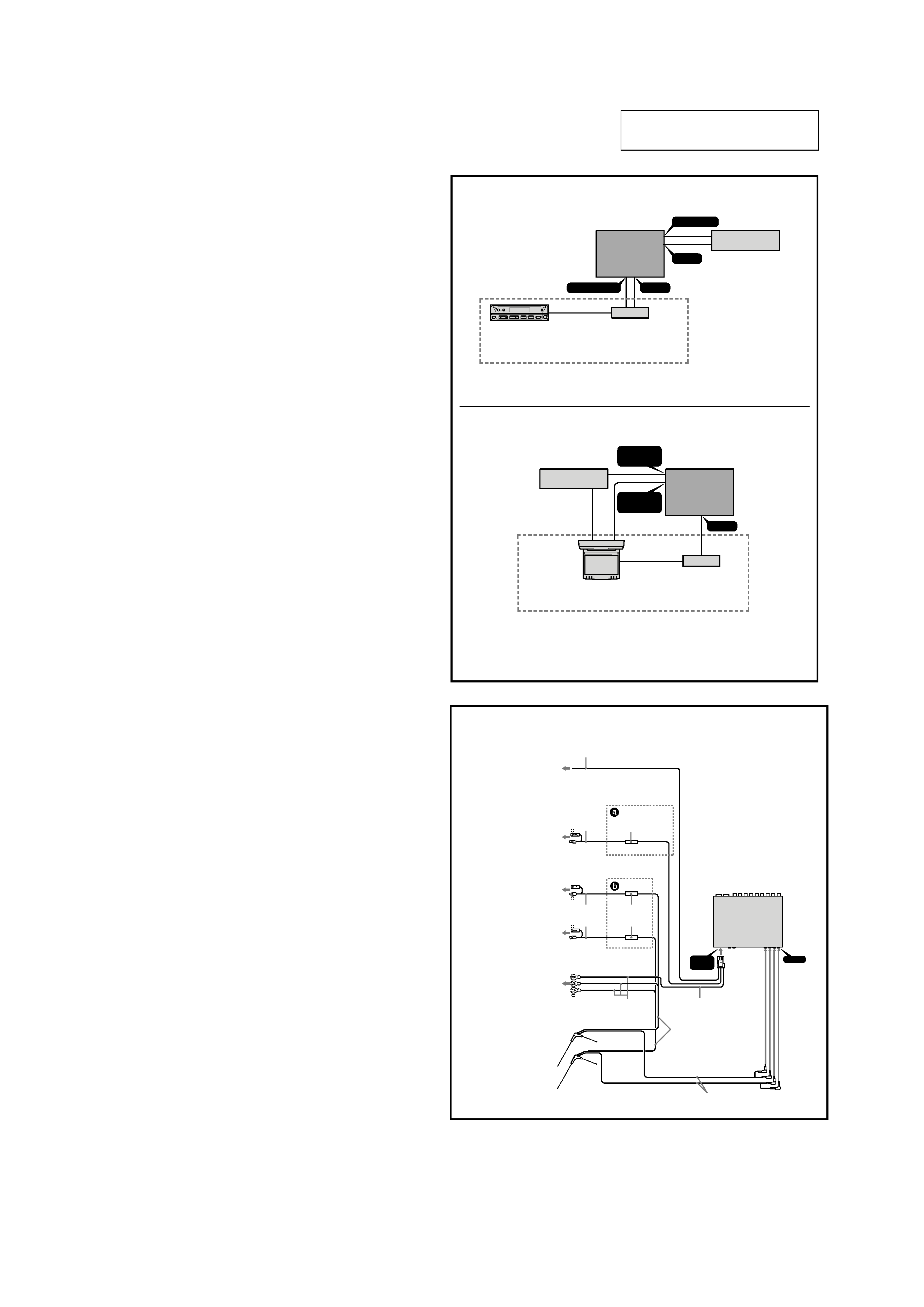
Connection example (2)
The XAV-7W is shown for the Sony BUS connection and the
XVM-R75 is shown for the other connection in this operating
instructions.
Power connection diagram (3)
Sony BUS connection diagram
(4-1)
When making the Sony BUS connection, the connected Media
Center (ex: XAV-7W) is only controllable with the wireless
remote commander supplied with the Media Center.
After connection
Set the TV SYSTEM selector on the side of the tuner unit, to
the correct position for your area.
Be sure to reset the connected Media Center main unit after
setting the TV system.
Position
Area
1
The United Kingdom
2
Europe and Italy
3China and Hong Kong
IR connection diagram (4-2)
· Be sure to set the SIGNAL SELECT switch on the tuner unit
according to the connected equipment, or the wireless remote
commander does not respond.
· The Sony BUS connection takes priority over the IR
connection.
SIGNAL SELECT OUT switch
Set the switch to "DVX-100" when DVX-100 is connected, and
set to "OTHERS" when other equipment is connected.
SIGNAL SELECT IN switch
Set to "XVM-R75" when XVM-R75 is connected, and set to
"OTHERS" when other equipment is connected.
Fuse (5 A)
5
Fuse (0.5 A)
Power supply lead (3- )
Aerial cord (3-
)
Before installation
·Install the aerials only on the rear window.
·Keep the aerials away from other aerials on the car, such as
for CB or amateur radio, cell phone, etc. If installed too close,
aerials may cause mutual interference.
·On days of high humidity (rain, fog, etc.), make sure that the
installation surface is fully dry before beginning the
installation. Wet conditions will reduce the adhesive strength
and may cause the aerials to fall off.
· If the installation surface is cold, warm it up first with the car
heater, rear window defogger, a hair dryer or similar. This
will increase adhesive strength.
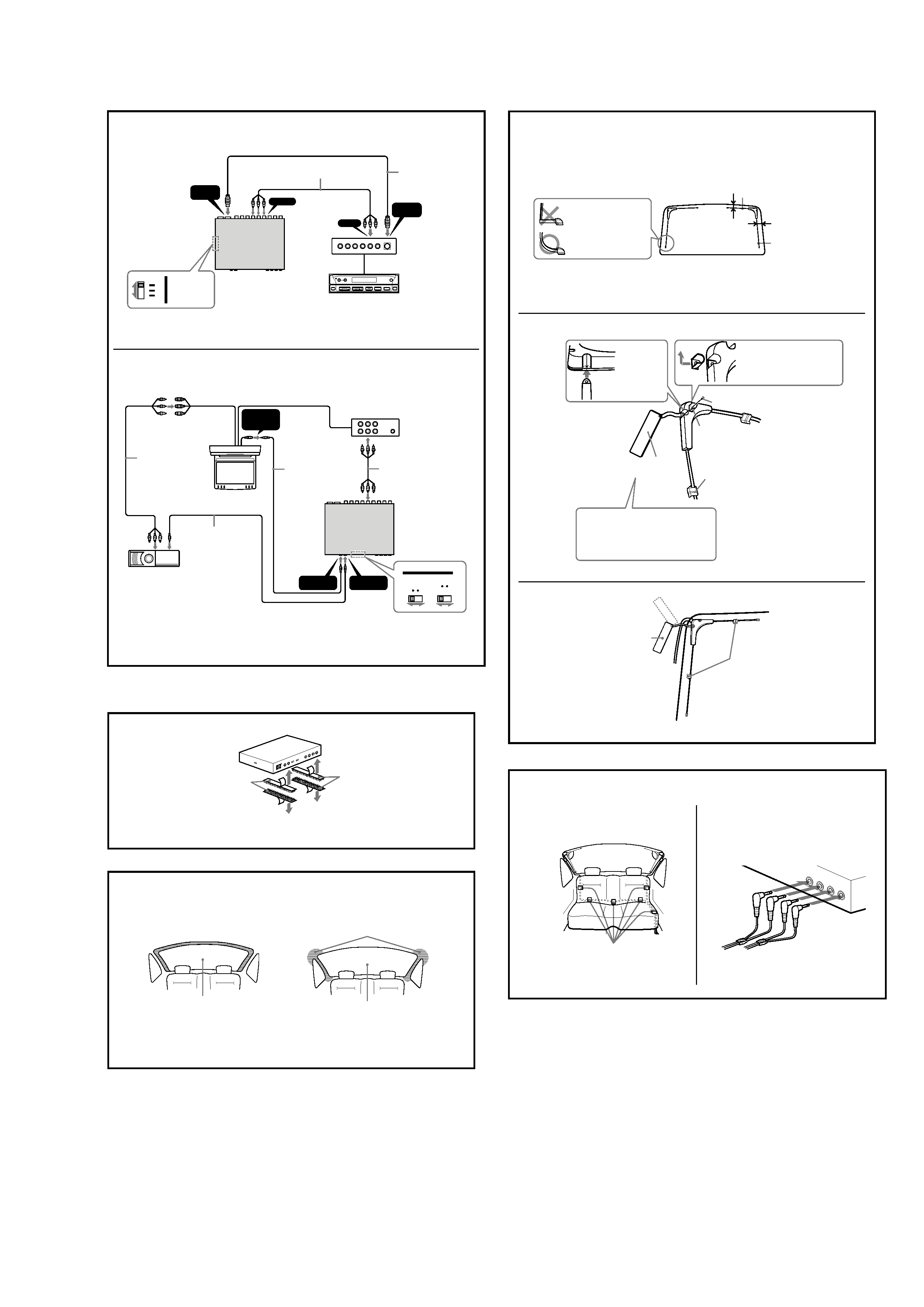
Installing the TV tuner unit (5)
Notes
· Ensure that the mounting surface is clean.
· Do not install the TV tuner unit
in locations subject to high temperatures.
in locations subject to direct sunlight, warm air from heater
outlets, or other locations that can get hot.
· When attaching the hook-and-loop fastener to the bottom of the
TV tuner unit, do not cover the model name plate in the center.
Keep the units and connection cables apart.
The Media Center main unit, the monitor, TV tuner unit, and RCA
interconnects should not be in close proximity. Otherwise noise
interference may affect the TV picture.
Installing the TV aerials (6)
Select a fairly flat section of the rear window for installation. If
the glass is strongly curved, the aerial may come loose. Wipe
the intended installation area with a dry cloth to remove any
moisture or dust.
In cars which have a lining (pillar) near the rear window,
remove the lining to gain access to the metal for use as ground.
It is not necessary to scratch off the paint from the metal
surface.
Checking the mounting position for
TV aerials (7-1)
Verify the left and right aerial positions. Pull the aerial rods
straight out, and provisionally fasten them with tape or similar.
Take care that the rods from the left and right aerials do not
overlap or touch each other.
In some cars, it may not be possible to extend the long rod fully.
In such a case, bend the rod in a smooth curve.
Notes
·When installing the aerials, try to avoid the defogger wiring.
· Do not touch the adhesive surface or reposition the aerial, as this
will decrease adhesive strength.
· The short aerial rod should be on top. If the long rod is on top,
sufficient sensitivity may not be achieved.
Attaching ground plate to aerials
body (7-2)
Be sure to mount the ground plate 7. Otherwise aerial
sensitivity will be reduced.
At this stage, the support clamper should only be snapped onto
the aerial but not yet glued in place.
After installation
· For 24 hours after installation, do not subject the aerials to
rain, splashes of water, or strong force.
· Before starting to drive, make sure that the aerials are securely
fastened.
·Also after starting to use the system, check the aerials from
time to time.
·Do not wipe the aerial body, rods, or cables with alcohol,
benzine, solvents, gasoline, wax, or similar, as this can cause
deformation or other damage.
· Reception may be impaired in the following locations:
Between tall buildings
In the vicinity of high voltage power lines
In the vicinity of flying aircraft
In the vicinity of electric trains and streetcars
In mountainous areas or areas far removed from broadcast
transmitters
In tunnels
Very close to commercial, amateur radio transmitters or
Sony TV tuner unit XT-P50V
Peeling off covering paper on
bottom of aerial and sticking aerial
onto mounting surface (7-3)
Stick the aerial onto the mounting surface, with the rods
extended straight.
Tip
Before attaching the aerials, make sure that the installation surface is
clean.
Precautions on TV aerial installation
·Mount the aerials only on the inside of the rear window.
·Do not install the aerials in locations which may obstruct the
driver's view.
· Be sure to connect the power supply lead to the ACC circuit.
·Keep the TV aerial cables as far away as possible from wiring
for an external amplifier and rear speakers.
Routing TV aerial cables (8-1)
Refer to the wiring diagram q;.
Notes
· Pull out the TV aerial rods as much as possible, but take care that
the rods do not cross or touch each other.
· In some cars, the shape or size of the rear window or the opening
of the rear gate may prevent installation of the aerials. For details,
consult your dealer.
Connecting TV aerial cables to TV
tuner unit (8-2)
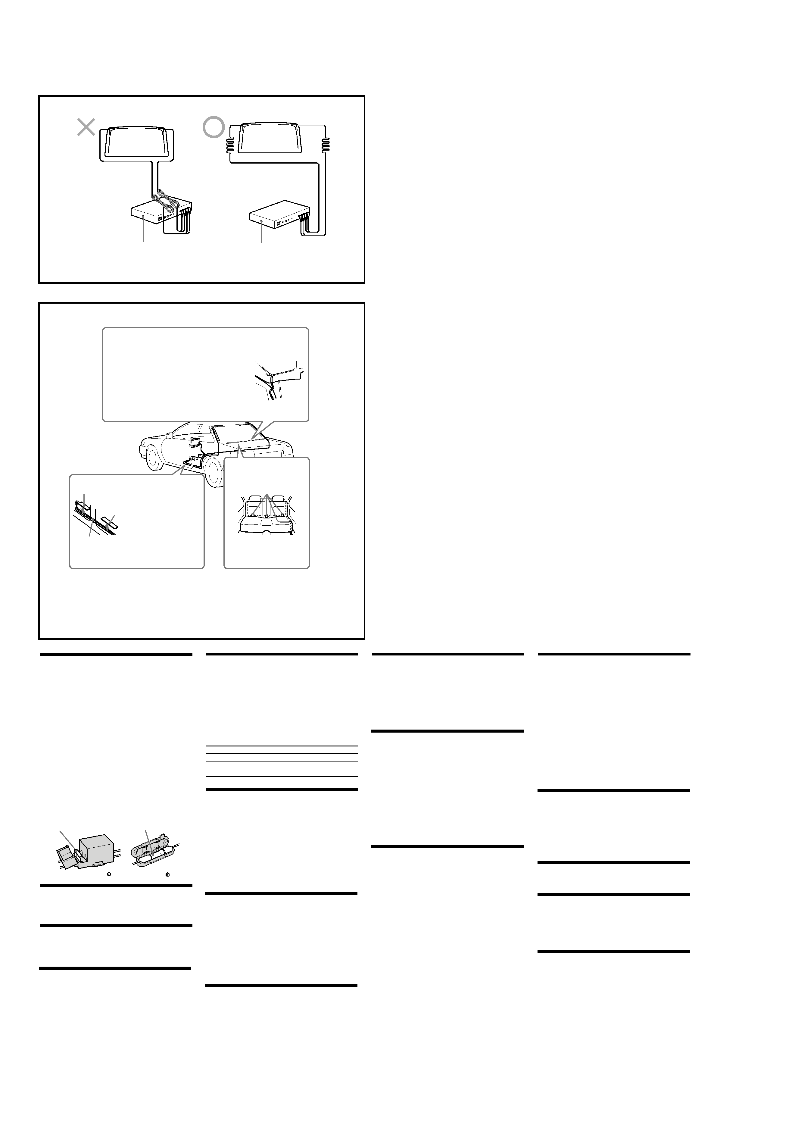
Dealing with excessive TV aerial
cable length (9)
If you coil the aerial cable and place it in the vicinity of the TV
tuner unit, noise may occur. Do not coil the cable, and keep it as
far as possible from the TV tuner unit.
Wiring (q;)
If cables become tangled with the gear shift lever or other
controls, there is a severe risk of accident.
When using the Media Center main unit or the monitor, keep
the RCA interconnects as far away from the aerial cables as
possible. Otherwise noise may appear on the TV picture.
9
q;
TV tuner unit XT-P50V
Fernsehtuner XT-P50V
Scuff plate
Abriebschutz
Aerial cables
Antennenkabel
Scuff plate
Abriebschutz
Remove scuff plate and route
cables under carpet.
Entfernen Sie den Abriebschutz
und verlegen Sie die Kabel
unter dem Teppich.
Rear seat cushion
Hintere Sitzbank
Secure with tape under seat.
Mit Klebeband unter dem Sitz
befestigen.
TV tuner unit XT-P50V
Fernsehtuner XT-P50V
Hatchback type car
Secure slack parts of the cable with cable clampers, so that the
cable cannot get caught in the door. Determine the optimum
position for the ground plate before attaching it.
Fahrzeugtyp mit Heckklappe
Befestigen Sie durchhängende Kabelteile mit Kabelschellen, so
dass das Kabel nicht in der Klappe eingeklemmt wird. Legen Sie
die optimale Position für die Masseplatte fest, bevor Sie sie
anbringen.
5
XT-P50V
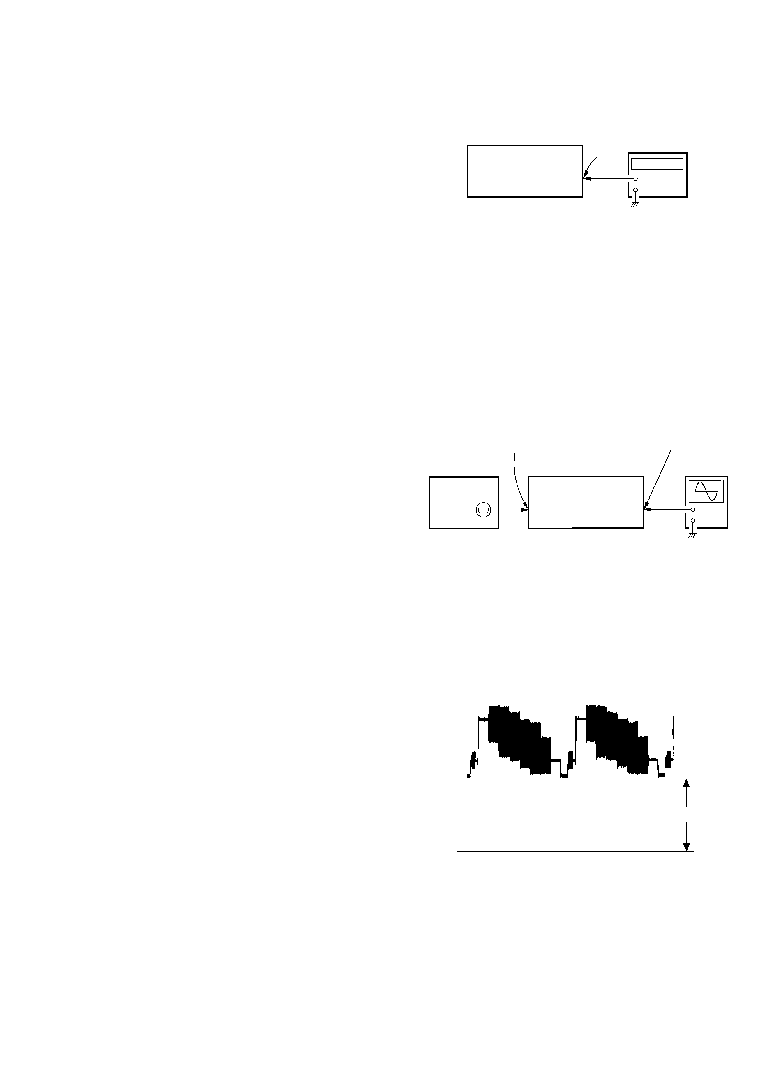
OSD ADJUSTMENT
Connection:
Adjusting Method:
1. Connect the PAL pattern generator to the INPUT VIDEO jack
(J104) on the HIDEAWAY board.
2. Connect the oscilloscope to the TP139 on the HIDEAWAY
board.
3. Adjust the RV100 on the HIDEAWAY board so that the clamp
voltage of the waveform on the oscilloscope becomes 1.5
±
0.1 V.
Adjusting and Connnecting Location: HIDEAWAY Board
SECTION 3
ELECTRICAL ADJUSTMENTS
DIVERSITY VCO FREQUENCY ADJUSTMENT
Connection:
Adjusting Method:
1. Connect the TP131 and GND on the HIDEAWAY board with
to activate the test mode.
2. Connect the frequency counter to the TP130 on the
HIDEAWAY board.
3. Adjust the CT100 on the HIDEAWAY board so that the value
of the frequency counter becomes 15.625
± 0.02 kHz.
Adjusting and Connnecting Location: HIDEAWAY Board
+
TP130
TV Tuner Unit
(XT-P50V)
frequency
counter
+
PAL pattern
generator
TP139
TV Tuner Unit
(XT-P50V)
oscilloscope
INPUT
VIDEO jack
(J104)
SECTION 2
TEST MODE
MICROPROCESSOR VERSION CHECK
Checking Method:
1. Set TV SYSTEM switch of XT-P50V to 2.
2. Connect XAV-7W and turn on the power for OFF screen sta-
tus.
3. Press the preset [4] button on the wireless remote commander
(RM-X118*) , press the preset [5] button next, then press the
preset [2] button for more than 2 seconds.
4. Switch mode of TV1, press the preset [6] button on the wire-
less remote commander (RM-X118*) to call No.6.
5. "21ch" is displayed on upper right of the screen and version of
the microprocessor is indicated below.
Note: When the power is turned off after the above is executed (just after
turning off, reset is executed), both SONY BUS connected/SONY
BUS disconnected status become initialized status. (TV ch becomes
factory shipping setting)
*) RM-X118 (Part No. 1-477-110-22) is wireless remote com-
mander which is an accessory of XAV-7W.
1.5
± 0.1 Vp-p
DC 0V