1
SERVICE MANUAL
US Model
Canadian Model
XTL-W70
· This set consists of the following units.
MOBILE COLOR TV
US/Canadian model
MONITOR
XVM-W71
TUNER UNIT
XT-992V
REMOTE COMMANDER
RM-X170
ANTENNA
VCA-114
Continued on next page
SPECIFICATIONS
Monitor
System
Liquid crystal color display
Display
Transparent TN LCD panel
Drive system
TFT active matrix system
Picture size
154.1
× 87.0 mm, 177 mm
(6 1/8
× 3 1/2 in., 7 in.)
(w
× h, diagonally)
Picture segment
336.960 (w 1440
× h 234)
Speaker type
ø36 mm (ø1 7/16 in.)
dynamic speaker
Power requirements
12 V DC car battery
(negative earth)
Current drain
Approx. 1.0 A
Dimensions
190
× 127.5 × 26.6 mm
(7 1/2
× 5 1/8 × 1 1/16 in.)
(w
× h × d)
Operating temperature
+5°C ~ +45°C
(41°F ~ 113°F)
Mass
Approx. 450 g (1 lb)
TV tuner unit
Television system
NTSC
Color system
TV: NTSC
Video: NTSC
Channel converge
VHF: 2 CH ~ 13 CH
UHF: 14 CH ~ 69 CH
Power requirements
12 V DC car battery
(negative earth)
Current drain
Approx. 0.5 A
Output terminals
Video output: RCA pin 1 Vp-p,
75 ohm
Audio output:RCA pin 10 dBs,
10 kohm
Monitor output: Square 16 -pin
(exclusive)
Tuner unit : XT-992V
Monitor : XVM-W71
Ver 1.1 2004. 08
9-873-250-02
2004H04-1
© 2004. 08
Sony Corporation
e Vehicle Company
Published by Sony Engineering Corporation

2
TABLE OF CONTENTS
1. GENERAL
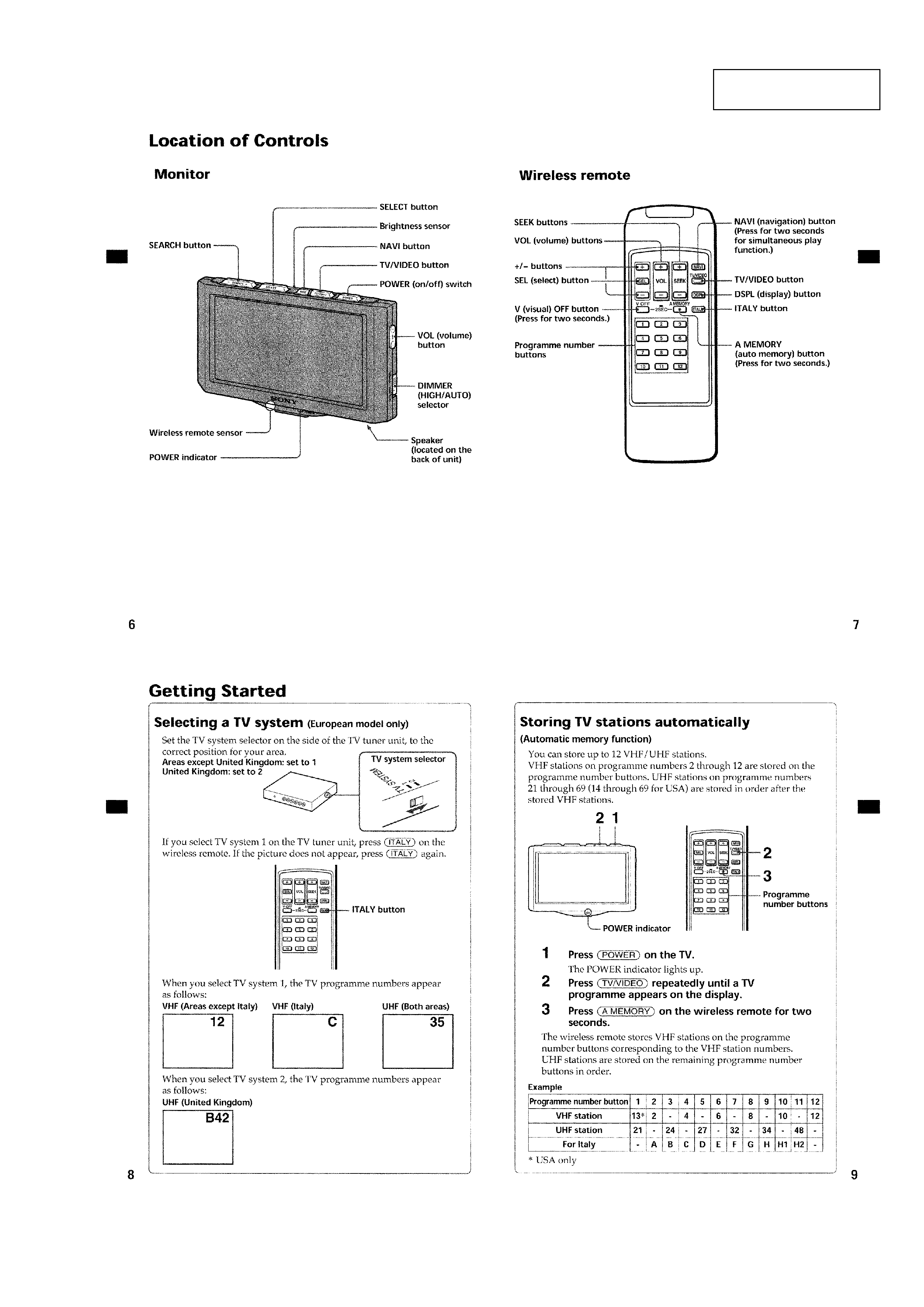
Location of Controls ............................................................... 3
Getting Started ........................................................................ 3
Watching a TV Programme .................................................... 4
Viewing the Wide Screen ....................................................... 4
Watching a Video .................................................................... 4
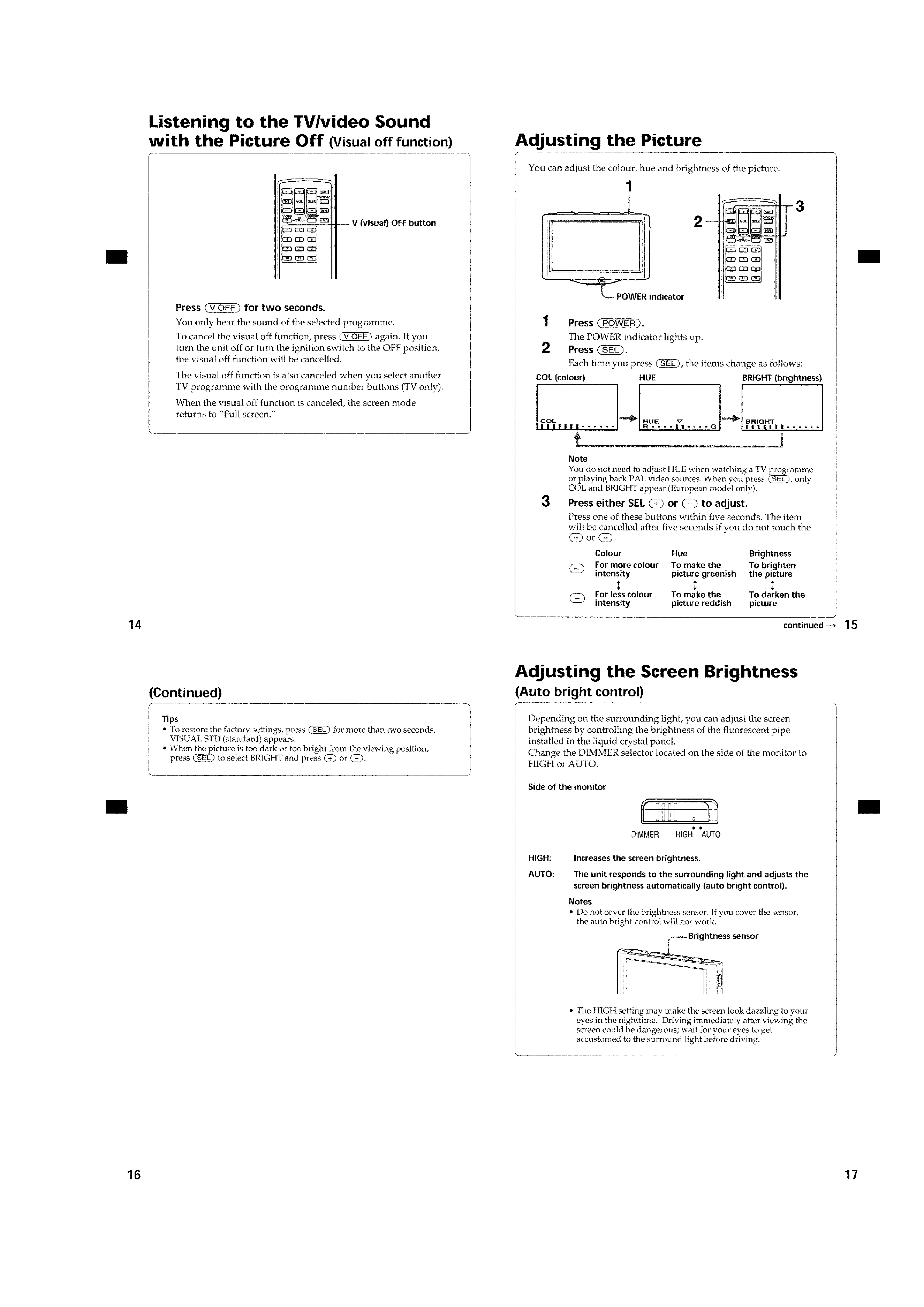
Listening to the TV/video Sound
with the Picture Off ................................................................ 5
Adjusting the Picture .............................................................. 5
Adjusting the Screen Brightness ............................................ 5
Using the Navigation System ................................................. 6
Listening to the TV/video Sound while Using
the Navigation System ............................................................ 6
Connections ............................................................................ 7
2. DISASSEMBLY
2-1. Cabinet Assy, Monitor (Rear) ............................................ 8
2-2. Sw Board, Monitor Board .................................................. 8
3. ELECTRICAL ADJUSTMENTS
Monitor Section ...................................................................... 9
Tuner Unit Section ............................................................... 13
4. DIAGRAMS
4-1. Block Diagram Monitor Section .................................. 15
4-2. Block Diagram Tuner Unit (Video) Section ................ 16
4-3. Block Diagram Tuner Unit (Audio) Section ................ 17
4-4. IC Pin Descriptions .......................................................... 18
4-5. Printed Wiring Board Monitor Section ........................ 20
4-6. Schematic Diagram Monitor Section (1/2) .................. 22
4-7. Schematic Diagram Monitor Section (2/2) .................. 23
4-8. Printed Wiring Board Monitor Switch Section ........... 24
4-9. Schematic Diagram Monitor Switch Section ............... 25
4-10. Printed Wiring Board Tuner Section ............................ 26
4-11. Schematic Diagram Tuner Section (1/3) ...................... 28
4-12. Schematic Diagram Tuner Section (2/3) ...................... 29
4-13. Schematic Diagram Tuner Section (3/3) ...................... 30
5. EXPLODED VIEWS
5-1. Monitor Section ............................................................... 35
5-2. Tuner Section ................................................................... 36
6. ELECTRICAL PARTS LIST ....................................... 37
Notes on Chip Component Replacement
· Never reuse a disconnected chip component.
· Notice that the minus side of a tantalum capacitor may be
damaged by heat.
Input terminals Video input (2 system): RCA pin 1 Vp-p,
75 ohm
Audio input: RCA pin 10 dBs, 10 kohm
Antenna input (4 system): mini plug
Navigation input: Square 16 -pin
(exclusive)
RCA pin:
Video 1 Vp-p, 75 ohm
Audio (monaural)
10 dBs, 10 kohm
Dimensions
202
× 30 × 140 mm (w × h × d)
(8
× 1 3/16 × 5 5/8 in.)
(w
× h × d)
Mass
Approx. 750 g (1 lb. 11 oz.)
Wireless remote
Power requirements
AA (R6) battery
× 2
Operable range Approx. 3 m (9.8 ft.)
Dimensions
60
× 19 × 166 mm
(2 3/8
× 3/4 × 6 5/8 in.)
(w
× h × d)
Mass
Approx. 125 g (4 oz.)
(including batteries)
TV antenna
Cord
5 m (16.4 ft.), 75 ohm
Supplied accessories
Wireless remote (1)
Power input cord (1)
Monitor cable (1)
TV antenna (1)
Parts for installation and
connections (1 set)
Mounting kit (1 set)
Design and specifications are subject to change
without notice.
XTL-W70
SAFETY-RELATED COMPONENT WARNING!!
COMPONENTS IDENTIFIED BY MARK 0 OR DOTTED LINE
WITH MARK 0 ON THE SCHEMATIC DIAGRAMS AND IN
THE PARTS LIST ARE CRITICAL TO SAFE OPERATION.
REPLACE THESE COMPONENTS WITH SONY PARTS WHOSE
PART NUMBERS APPEAR AS SHOWN IN THIS MANUAL OR
IN SUPPLEMENTS PUBLISHED BY SONY.
ATTENTION AU COMPOSANT AYANT RAPPORT
À LA SÉCURITÉ!!
LES COMPOSANTS IDENTIFIÉS P
AR UNE MARQUE 0SUR LES
DIAGRAMMES SCHÉMA
TIQUES ET LA LISTE DES PIÈCES
SONT CRITIQUES POUR LA SÉCURITÉ DE FONCTIONNEMENT .
NE REMPLACER CES COMPOSANTS QUE P
AR DES PIÈCES
SONY DONT LES NUMÉROS SONT DONNÉS DANS CE MANUEL
OU DANS LES SUPPLÉMENTS PUBLIÉS P
AR SONY .
3
XTL-W70
SECTION 1
GENERAL
This section is extracted
from instruction manual.

4
XTL-W70
5
XTL-W70