1
SERVICE MANUAL
US Model
Hong Kong Model
XTL-750W
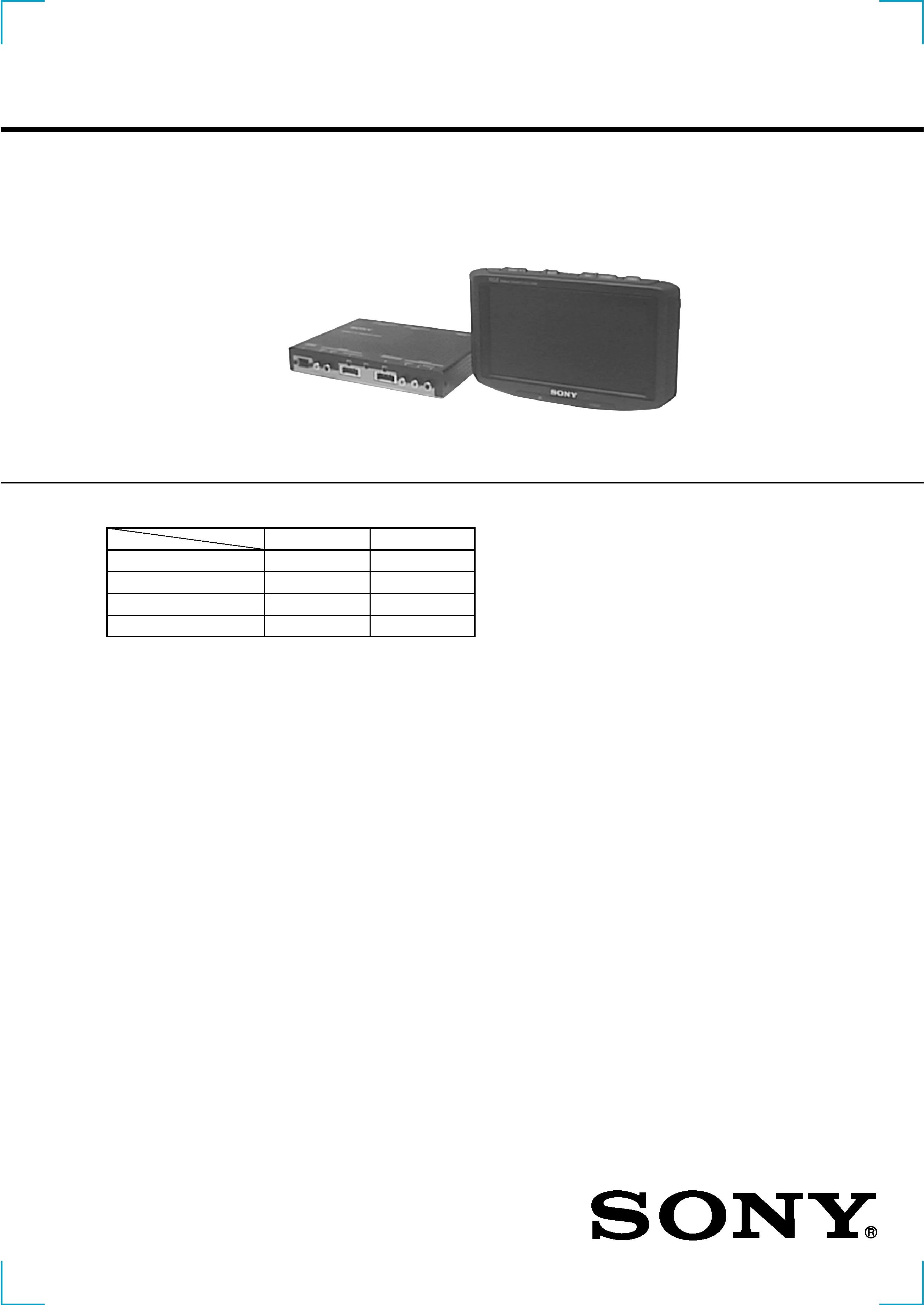
· This set consists of the following units.
MOBILE COLOR TV
US model
Hong Kong model
MONITOR
XVM-752W
XVM-751W
TUNER UNIT
XT-992V
XT-991V
REMOTE COMMANDER
RM-X63N
RM-X63E
ANTENNA
VCA-114
VCA-114
Continued on next page
SPECIFICATIONS
Monitor (XVM-752W: US, XVM-751W: Hong Kong)
System
Liquid crystal color display
Display
Transparent TN LCD panel
Drive system
TFT active matrix system
Picture size
7 in.; 155.52
× 87.75 mm,
178.57 mm
(w
× h, diagonally)
Picture segment
336,960 (w 1440
× h 234)
Speaker type
35
× 20 mm dynamic speaker × 2
Power requirements
12 V DC car battery
(negative ground)
Current drain
Approx. 1.0 A
Dimensions
215
× 126.5 × 34 mm (w × h × d)
Operating temperature
5°C ~ +45°C
Mass
Approx. 650 g
TV tuner unit (XT-992V: US,
XT-991V: Hong Kong)
Television system
Hong Kong:
CCIR I,D,K system
US:
NTSC
Color system
Hong Kong:
TV: PAL
Video: PAL, NTSC
US:
TV: NTSC
Video: NTSC
Channel converge
VHF: 1 CH ~ 12 CH (Hong Kong)
2 CH ~ 13 CH (US)
UHF: 14 CH ~ 69 CH (US)
21 CH ~ 69 CH (Hong Kong)
Power requirements
12 V DC car battery
(negative ground)
Current drain
Approx. 0.5 A
Output terminals
Video output: RCA pin 1 Vp-p,
75 ohm
Audio output: RCA pin 10 dBs,
10 kohm
Monitor output: Square 16 -pin
(exclusive)
Tuner unit :
XT-992V (US model)
XT-991V (Hong Kong model)
Monitor :
XVM-752W (US model)
XVM-751W (Hong Kong model)
Ver 1.1 2001. 03
Sony Corporation
Audio Entertainment Group
General Engineering Dept.
9-925-662-12
2001C0400-1
© 2001. 3

2
TABLE OF CONTENTS
1. GENERAL
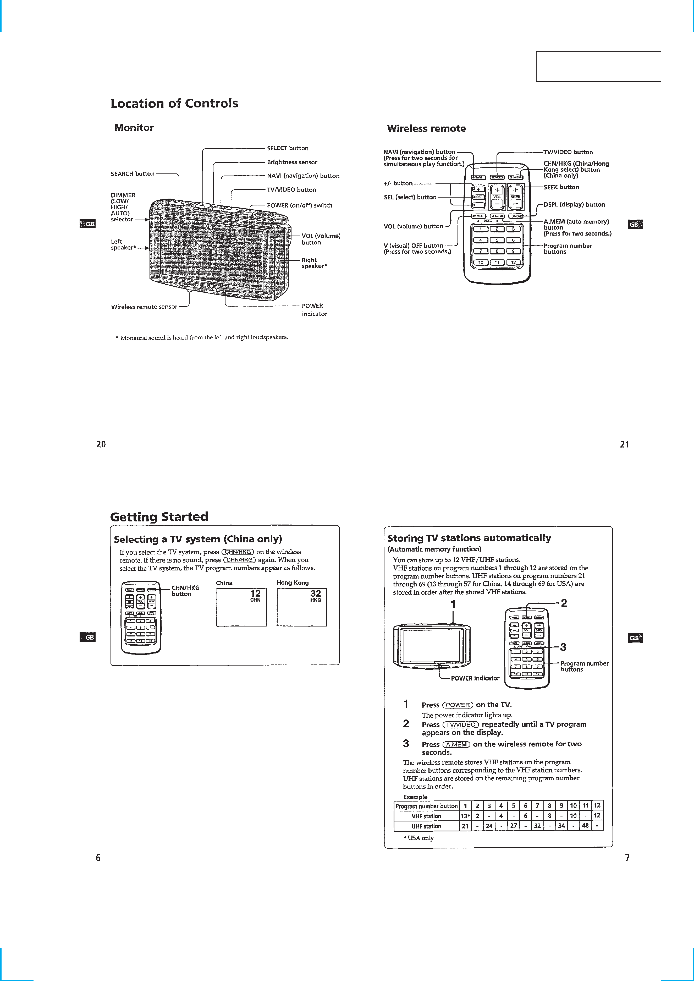
Location of Controls ............................................................... 3
Getting Started ........................................................................ 3
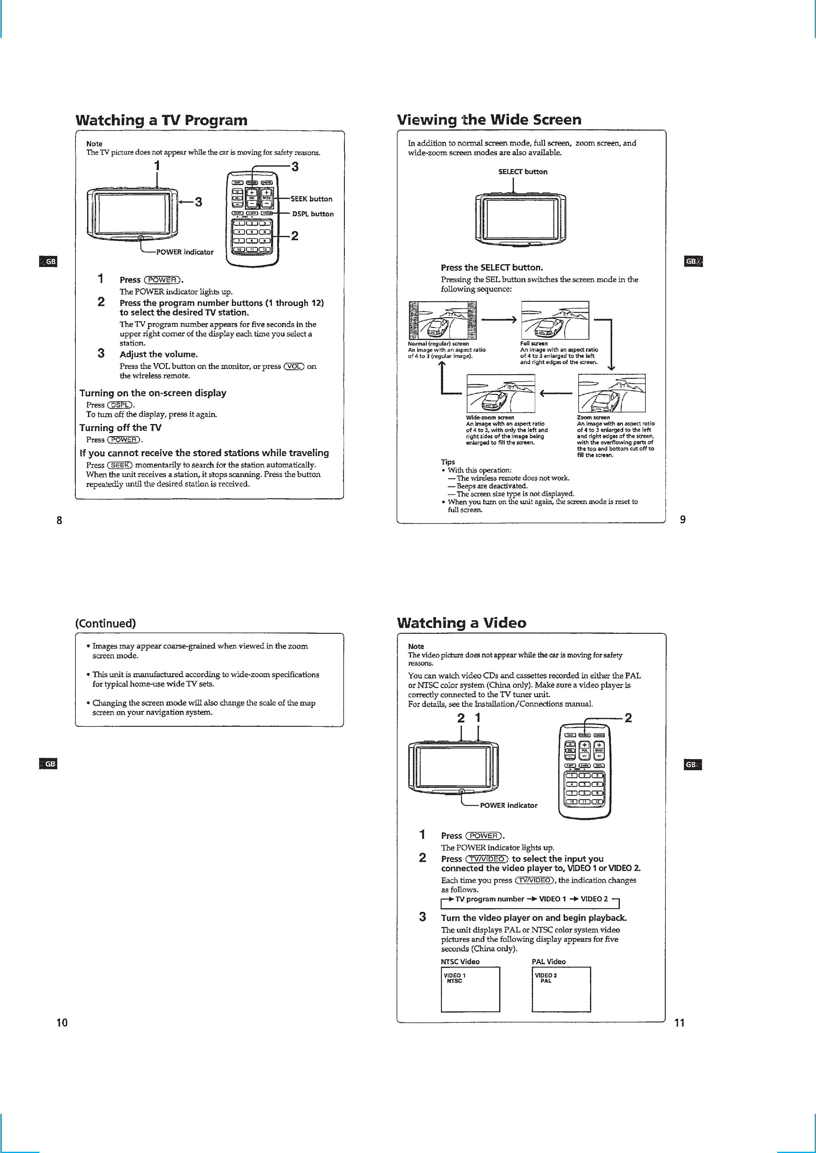
Watching a TV Program ......................................................... 4
Viewing the Wide Screen ....................................................... 4
Watching a Video .................................................................... 4
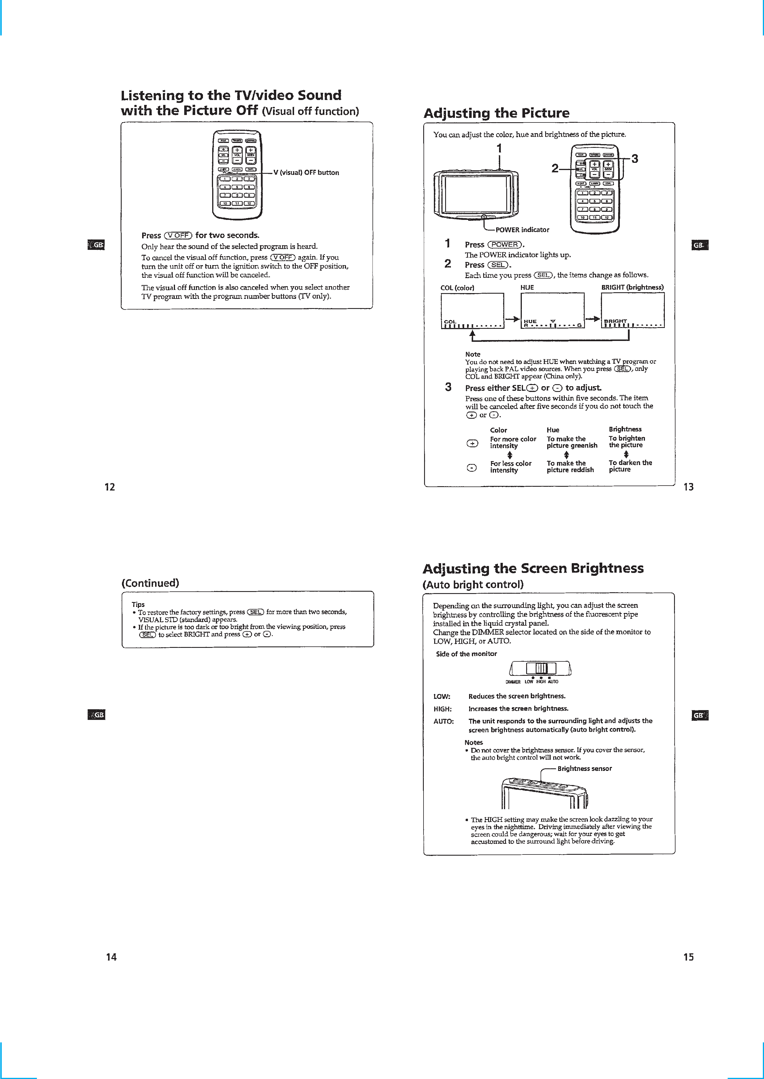
Listening to the TV/video Sound
with the Picture Off ................................................................ 5
Adjusting the Picture .............................................................. 5
Adjusting the Screen Brightness ............................................ 5
Using the Navigation System ................................................. 6
Listening to the TV/video Sound while Using
the Navigation System ............................................................ 6
Connections ............................................................................ 7
2. DISASSEMBLY
2-1. Rear Panel Assy ................................................................. 8
2-2. Main Board ........................................................................ 8
3. ELECTRICAL ADJUSTMENTS
Monitor Section ...................................................................... 9
Tuner Unit Section ................................................................ 12
4. DIAGRAMS
4-1. Block Diagram Monitor Section .................................. 15
4-2. Block Diagram Tuner Unit (Video) Section ................ 17
4-3. Block Diagram Tuner Unit (Audio) Section ................ 19
4-4. Printed Wiring Boards Monitor Section ....................... 21
4-5. Schematic Diagram Monitor Section (1/2) .................. 25
4-6. Schematic Diagram Monitor Section (2/2) .................. 27
4-7. Printed Wiring Board Tuner Unit (US model) ............. 29
4-8. Printed Wiring Board
Tuner Unit (Hong Kong model) ................................... 33
4-9. Schematic Diagram Tuner Unit (1/4) ........................... 37
4-10. Schematic Diagram Tuner Unit (2/4) ........................... 39
4-11. Schematic Diagram Tuner Unit (3/4) ........................... 41
4-12. Schematic Diagram Tuner Unit (4/4) ........................... 43
5. EXPLODED VIEWS
5-1. Monitor Section ............................................................... 49
5-2. Tuner Section ................................................................... 50
6. ELECTRICAL PARTS LIST ................................... 51
Notes on Chip Component Replacement
· Never reuse a disconnected chip component.
· Notice that the minus side of a tantalum capacitor may be
damaged by heat.
Input terminals Video input (2 system): RCA pin 1 Vp-p,
75 ohm
Audio input: RCA pin 10 dBs, 10 kohm
Antenna input: mini plug
Navigation input: Square 16 -pin
(exclusive)
RCA pin:
Video 1 Vp-p, 75 ohm
Audio (monaural)
10 dBs, 10 kohm
Dimensions
202
× 30 × 140 mm (w × h × d)
Mass
Approx. 750 g
Wireless remote (RM-X63N: US,
RM-X63E: Hong Kong)
Power requirements
AA (R6) battery
× 2
Operable range Approx. 3 m
Dimensions
62
× 25 × 115 mm (w × h × d)
Mass
Approx. 100 g
(including batteries)
TV antenna (VCA-114)
Cord
5 m (196 7/8 in.), 75 ohm
Supplied accessories
Wireless remote RM-X63N (1)
(US model)
Wireless remote RM-X63E (1)
(Hong Kong model)
Power input cord (1)
Monitor cable (1)
TV antenna VCA-114 (1)
Parts for installation and
connections (1 set)
Cleaning cloth (1)
Design and specifications are subject to change
without notice.
3
SECTION 1
GENERAL
This section is extracted
from instruction manual.
4
5