SERVICE MANUAL
MOBILE TV TUNER
US Model
Taiwan Model
Korean Model
XT-63V
Ver 1.1 2002.09
9-873-929-02
Sony Corporation
2002I0500-1
e Vehicle Company
C
2002.09
Published by Sony Engineering Corporation
SPECIFICATIONS
The XT-63V is composed of the following models.
TV tuner unit
XT-63V
TV Antenna
VCA-116
·XT-63V is TV tuner unit only
for XAV-7W.
Reception format
NTSC
Channels
2 - 13 (VHF)
14 - 69 (UHF)
(Monaural)
Power requirements
12 V DC, from car battery
(negative ground)
Power consumption
0.7 A
Inputs
Video/audio (Sony bus
compatible, 1)
Sony bus (1)
TV antenna (4)
Outputs
Video/audio (Sony bus
compatible, 1)
Sony bus (1)
Dimensions
Approx. 185.4
× 29.8 × 136.6
mm
(7 3/8
× 1 3/16 × 5 1/2 in.)
(W
× H × D)
Mass
Approx. 0.7 kg (1 lb 9 oz)
Design and specifications are subject to change
without notice.

2
XT-63V
TABLE OF CONTENTS
1.
GENERAL ................................................................... 3
2.
ELECTRICAL ADJUSTMENTS ......................... 5
3.
DIAGRAMS
3-1. Block Diagram AUDIO Section ...............................
8
3-2. Block Diagram VIDEO Section ...............................
9
3-3. Block Diagram
BUS CONTROL/POWER SUPPLY Section ............ 10
3-4. Note for Printed Wiring Board and
Schematic Diagrams ....................................................... 11
3-5. Printed Wiring Board
HIDE Board (Component Side) ................................ 12
3-6. Printed Wiring Board
HIDE Board (Conductor Side) .................................. 13
3-7. Schematic Diagram HIDE Board (1/3) ................... 14
3-8. Schematic Diagram HIDE Board (2/3) ................... 15
3-9. Schematic Diagram HIDE Board (3/3) ................... 16
3-10. IC Pin Function Description ........................................... 20
4.
EXPLODED VIEW ................................................... 22
5.
ELECTRICAL PARTS LIST ............................... 23
Notes on chip component replacement
·Never reuse a disconnected chip component.
· Notice that the minus side of a tantalum capacitor may be dam-
aged by heat.
Flexible Circuit Board Repairing
·Keep the temperature of the soldering iron around 270 °C dur-
ing repairing.
· Do not touch the soldering iron on the same conductor of the
circuit board (within 3 times).
· Be careful not to apply force on the conductor when soldering
or unsoldering.
3
XT-63V
SECTION 1
GENERAL
This section is extracted from
instruction manual.
2
DISC
SEEK
SOURCE
MODE
AT T
OFF
OPEN/
CLOSE
.>
VOL
CONTROL (OUT)
OUTPUT
INPUT
CONTROL (IN)
3
Hook-and-loop fastener 4
Bande Velcro 4
Cinta Velcro 4
Hook-and-loop fastener 4
Bande Velcro 4
Cinta Velcro 4
On installation surface
Sur la surface d'installation
Sobre la superficie de instalacion
TV tuner unit
Tuner de television
Unidad del
sintonizador de
television
XT-63V
Media Center
Media Center
Centro de media
XAV-7W
Connection box XA-114
(supplied with XAV-7W)
Boite de raccordement XA-114
(fournie avec XAV-7W)
Caja de conexion XA-114
(suministrado con XAV-7W)
CD/ MD changer, or
Source selector XA-C30
Changeur de CD/MD ou
selecteur de source
XA-C30
Cambiador de discos
CD/MD, o selector de
fuente XA-C30
4
OUTPUT
ANT IN
POWER
DC 12V
CONTROL
(OUT)
To the +12 V power terminal
which is energized at all times
A la borne d'alimentation +12
V traversee par le courant a
tout moment
Al terminal de suministro de
alimentacion de +12 V
permanentemente energizado
To a metal surface of the car
A la surface metallique de la
voiture
A una superficie metalica del
automovil
Yellow
Jaune
Amarillo
Filter +
fuse (5A)
Filtre +
fusible (5A)
Filtro +
fusible (5A)
Red
Rouge
Rojo
Fuse (0.5 A)
Fusible (0.5 A)
Fusible (0.5 A)
Black
Noir
Negro
TV antenna 5
Antenne de television 5
Antena de television 5
Power supply leads 1
(5.5 m)
Fil d'alimentation 1
(5,5 m)
Conductores de
suministro de
alimentacion 1 (5,5 m)
Bus cable 2 (5.3 m)
Cable de bus 2 (5,3 m)
Cable de bus 2 (5,3 m)
RCA interconnects 3 (5.3 m)
Interconnexions RCA 3 (5,3 m)
Cables interconectores de RCA 3 (5,3 m)
To the connection box
A la boite de raccordement
A la caja de conexion
XT-63V
5
Inside of rear window
Intérieur de la lunette arrière
Dentro de la ventanilla trasera
Peel off lining here
Détachez la garniture ici.
Despegue el forro de aquí.
Inside of rear window
Intérieur de la lunette arrière
Dentro de la ventanilla trasera
5
6
1
2
3
7
1
2
Inside of rear window
Intérieur de la lunette arrière
Dentro de la ventanilla trasera
Peel off lining here
Détachez la garniture ici.
Despegue el forro de aquí.
Do not bend sharply
Ne recourbez pas à angle
aigu
No doble demasiado.
Inside of rear window
Intérieur de la lunette arrière
Dentro de la ventanilla trasera
Bend in a smooth curve
Courbez naturellement
Doble con una curva suave.
Leave clearance of at least 50 mm
Ménagez un jeu d'au moins 50 mm
Deje una holgura de 50 mm por lo menos.
Short
Court
Corta
Long
Long
Larga
Insert between
metal plates
Insérez entre les
plaques
métalliques
Inserte entre las
placas metálicas.
Slide terminal cover forward to
remove
Glissez le capuchon de borne en
avant pour le retirer.
Deslice la cubierta de terminales
hacia delante para extraerla.
Screw
Vis
Tornillo
Terminal cover
Capuchon de borne
Cubierta de terminales
Ground plate 6
Plaque de mise à
la terre 6
Placa de puesta
a masa 6
Bring into contact with metal surface of the
car
Mettez au contact de la surface métallique
de la voiture
Ponga en contacto con una superficie
metálica del automóvil.
Support clamper 7
Pince de support 7
Abrazadera de soporte 7
Attach while adjusting angle and
position
Ajustez l'angle et la position puis
collez
Fije mientras ajuste el ángulo y la
posición.
Fix support clamper in center of antenna
rod
Fixez la pince de support au centre de la
tige d'antenne.
Fije la abrazadera de soporte en el centro
de la varilla de la antena.
Leave clearance of at least 50 mm
Ménagez un jeu d'au moins 50 mm
Deje una holgura de 50 mm por lo
menos.
Inside of rear window
Intérieur de la lunette
arrière
Dentro de la ventanilla
trasera
Secure with tape under seat
Fixez sous le siège avec un ruban
adhésif
Asegure con cinta debajo del asiento.
TV tuner unit
Tuner de television
Unidad del sintonizador de television
XT-63V
90
°
90
°
4
XT-63V
8
9
TV tuner unit
Tuner de télévision
Unidad del Sintonizador de televisión
Hatchback type car
Secure slack parts of the cable with cable clampers, so
that the cable cannot get caught in the door. Determine
the optimum position for the ground plate before
attaching it.
TV tuner unit
Tuner de télévision
Unidad del Sintonizador de televisión
Scuff plate
Plaque de frottement
Placa taponadora
Antenna cables
Câbles d'antenne
Cables de las antenas
Scuff plate
Plaque de frottement
Placa taponadora
Remove scuff plate and
route cables under carpet.
Retirez la plaque de
frottement et acheminez
les câbles sous le tapis.
Quite la placa de
taponadora y enrute los
cables por debajo de la
alfombra.
Rear seat cushion
Coussin de siège arrière
Placa taponadora
Voiture à hayon arrière
Immobilisez les parties desserrées du câble avec des
serre-fils, de sorte que les câbles ne se coincent pas dans
la portière. Déterminez la position optimum pour la
plaque de mise à la terre avant de la fixer.
Automóvil de tipo con portón trasero
Asegure las partes flojas de los cables con los sujetacables para
que no puedan pillarse con el portón. Determine la posición
óptima para la placa de puesta a masa antes de fijarla.
Secure with tape under seat
Fixez sous le siège avec un
ruban adhésif
Asegure con cinta debajo del
asiento.
Before installation
·Install the antennas only on the rear window.
·Keep the antennas away from other antennas on the car,
such as for CB or amateur radio, cell phone, etc. If
installed too close, antennas may cause mutual
interference.
·On days with high humidity (rain, fog, etc.), make sure
that the installation surface is fully dry before beginning
the installation. Wet conditions will reduce the adhesive
strength and may cause the antennas to fall off.
·If the installation surface is cold, warm it up first with
the car heater, rear window defogger, a hair dryer or
similar. This will increase adhesive strength.
Before installing the TV antennas (5)
Select a fairly flat section of the rear window for
installation. If the glass is strongly curved, the antenna
may come loose. Wipe the intended installation area with
a dry cloth to remove any moisture or dust.
In cars which have a lining (pillar) near the rear window,
remove the lining to gain access to the metal for use as
ground.
It is not necessary to scratch off the paint from the
metal surface.
Check mounting position for TV antennas (6-1)
Verify the left and right antenna positions. Pull the
antenna rods straight out, and provisionally fasten them
with tape or similar. Take care that the rods from the left
and right antennas do not overlap or touch each other.
In some cars, it may not be possible to extend the long rod
fully. In such a case, bend the rod in a smooth curve.
Notes
·When installing the antennas, try to avoid the defogger
wiring.
·Do not touch the adhesive surface or reposition the
antenna, as this will decrease adhesive strength.
·The short antenna rod should be on top. If the long rod
is on top, sufficient sensitivity may not be achieved.
Attach ground plate 6 to antenna body (6-2)
Be sure to mount the ground plate. Otherwise antenna
sensitivity will be reduced.
At this stage, the support clamper should only be
snapped onto the antenna but not yet glued in place.
After installation
·For 24 hours after installation, do not subject the
antennas to rain, splashes of water, or strong force.
·Before starting to drive, make sure that the antennas are
securely fastened.
·Also after starting to use the system, check the antennas
from time to time.
·Do not wipe the antenna body, rods, or cables with
alcohol, benzine, solvents, gasoline, wax, or similar, as
this can cause deformation or other damage.
·Reception may be impaired in the following locations:
1. Between tall buildings
2. In the vicinity of high voltage power lines
3. In the vicinity of flying aircraft
4. In the vicinity of electric trains and streetcars
5. In mountainous areas or areas far removed from broadcast
transmitters
6. In tunnels
7. Very close to commercial or amateur radio transmitters
Sony TV Tuner Unit XT-63V
Peel off covering paper on bottom of antenna and
stick antenna onto mounting surface ( 6-3)
Stick the antenna onto the mounting surface, with the
rods extended straight.
Tip
Before attaching the antennas, make sure that the
installation surface is clean.
TV antenna installation precautions
·Mount the antennas only on the inside of the rear
window.
·Do not install the antennas in locations which may
obstruct the driver's view.
·Be sure to connect the power supply lead to the ACC
circuit.
·Keep the TV antenna cables as far away as possible from
wiring for an external amplifier and rear speakers.
Route TV antenna cables (7-1)
Refer to the wiring diagram below.
Notes
·Pull out the TV antenna rods as much as possible, but
take care that the rods do not cross or touch each other.
·In some cars, the shape or size of the rear window or the
opening of the rear gate may prevent installation of the
antennas.
For details, please consult your dealer.
Connect TV antenna cables to TV tuner unit
(7-2)
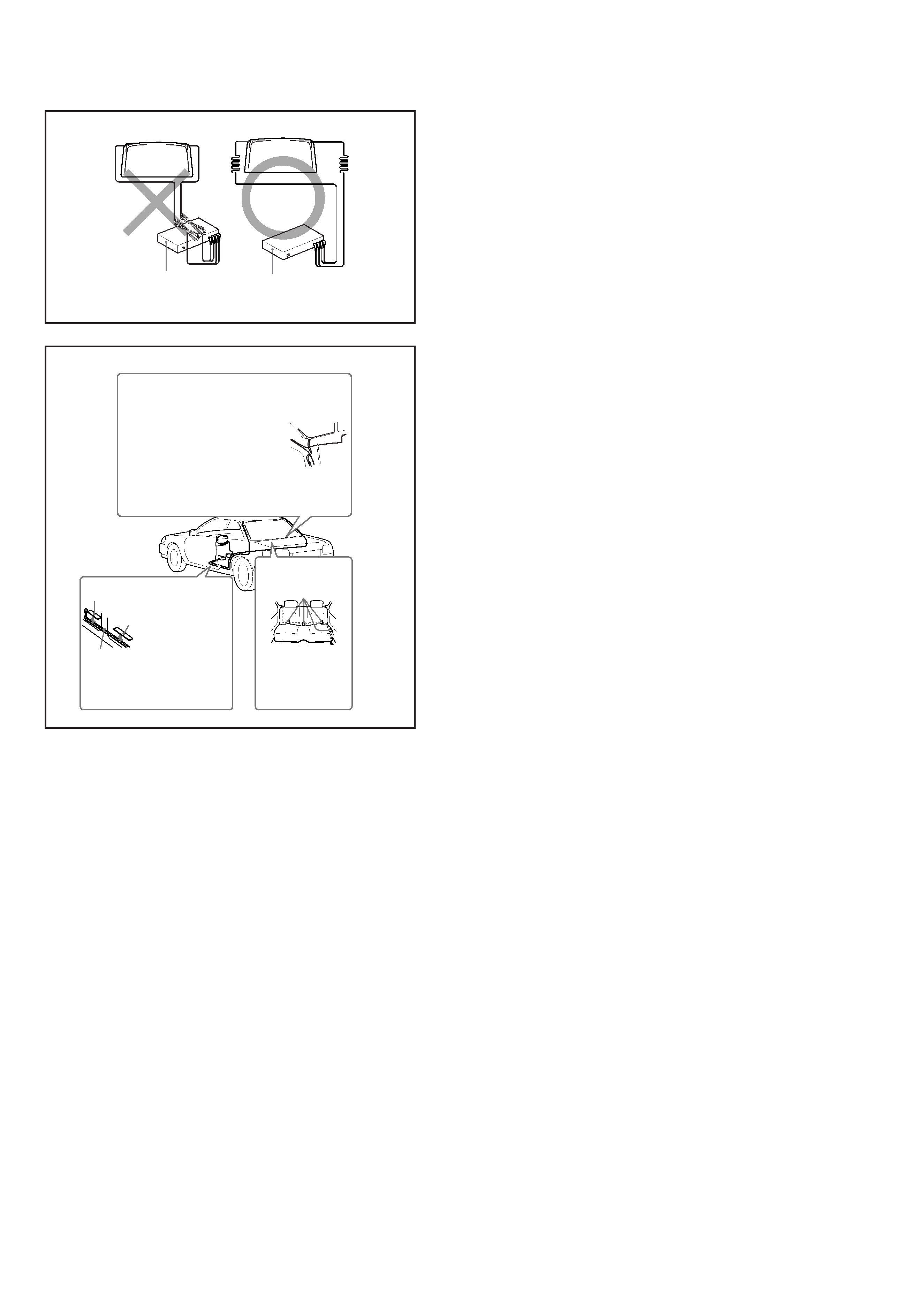
Dealing with excessive TV antenna cable
length (8)
If you coil the antenna cable and place it in the vicinity of
the TV tuner unit, noise may occur. Do not coil the cable,
and keep it as far as possible from the TV tuner unit.
Wiring (9)
If cables become tangled with the gear shift lever or other
controls, there is a severe risk of accident.
When using the Media Center main unit, keep the RCA
interconnects as far away from the antenna cables as
possible. Otherwise noise may appear on the TV picture.
Precautions
·This unit is designed for negative ground 12 V DC systems
only.
·Do not get the wires under a screw, or caught in moving
parts (e.g. seat railing).
·Before making connections, turn the car ignition off to avoid
short circuits.
·Connect the yellow and red power input leads only after all
other leads have been connected.
·Run all ground wires to a common ground point.
·Be sure to insulate any loose unconnected wires with
electrical tape for safety.
Notes on the power supply cord (yellow)
·When connecting this unit in combination with other stereo
components, the connected car circuit's rating must be
higher than the sum of each component's fuse.
·When no car circuits are rated high enough, connect the unit
directly to the battery.
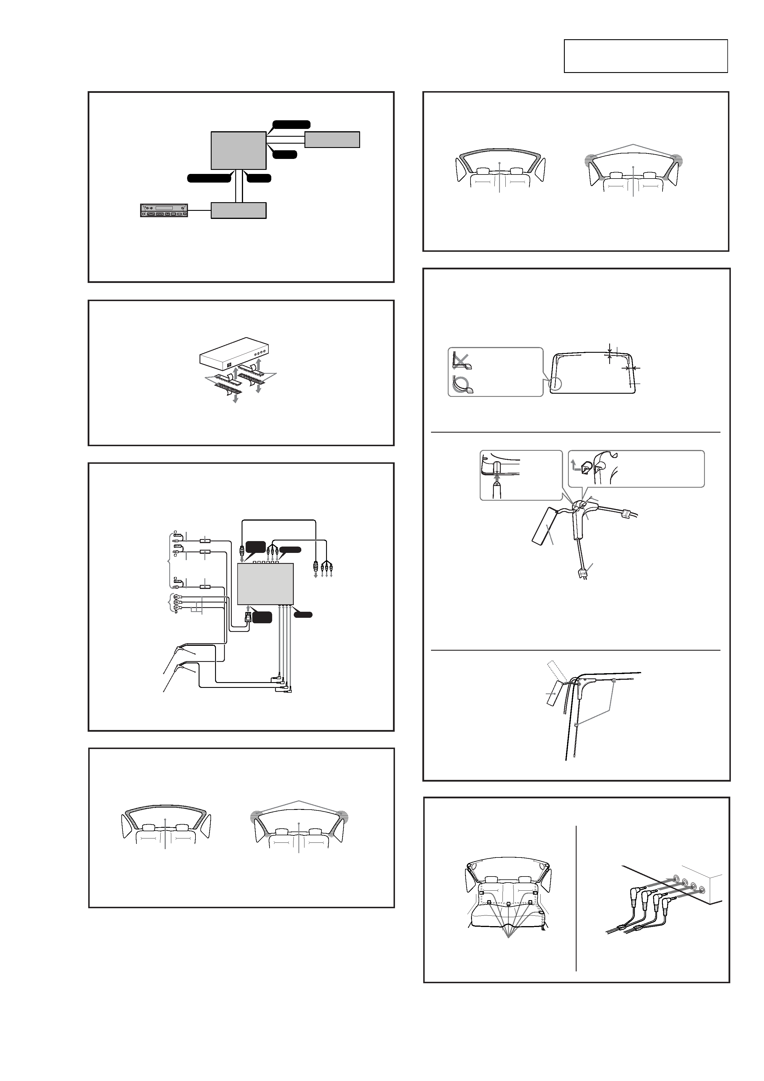
Parts list (1)
·The numbers in the list are keyed to those in the
instructions.
· Use 8 and 9 to organize cords.
Connection Example (2)
Installing the TV Tuner Unit (3)
Notes
·Ensure that the mounting surface is clean.
·Do not install the TV tuner unit
-in locations subject to high temperatures
-in locations subject to direct sunlight, warm air from heater
outlets, or other locations that can get hot.
·When attaching the hook-and-loop fastener to the
bottom of the TV tuner unit, do not cover the model
name plate in the center.
Keep the units and connection cables apart.
The Media Center main unit, TV tuner unit, and RCA
interconnects should not be in close proximity. Otherwise
noise interference may affect the TV picture.
Connection Diagram (4)
5
XT-63V
SECTION 2
ELECTRICAL ADJUSTMENTS
TV TUNER SECTION
0dBµV = 1µV
EQUIPMENT USED
For electrical adjustment, the following measuring instruments are
used:
· TV Tuner Unit (XT-63V)
· Media Center Main Unit (XAV-7W)
· Connection Box (XA-114)
· TV SSG
· Oscilloscope
· Synchroscope
· Digital Voltmeter
·Frequency Counter
·Level Meter
·Regulated Power Supply
SETUP FOR ADJUSTMENT
The TV tuner adjustment uses, as an adjusting signal, the video
signal generated from the TV SSG.
Perform adjustment after making sure that this signal satisfies the
specification.
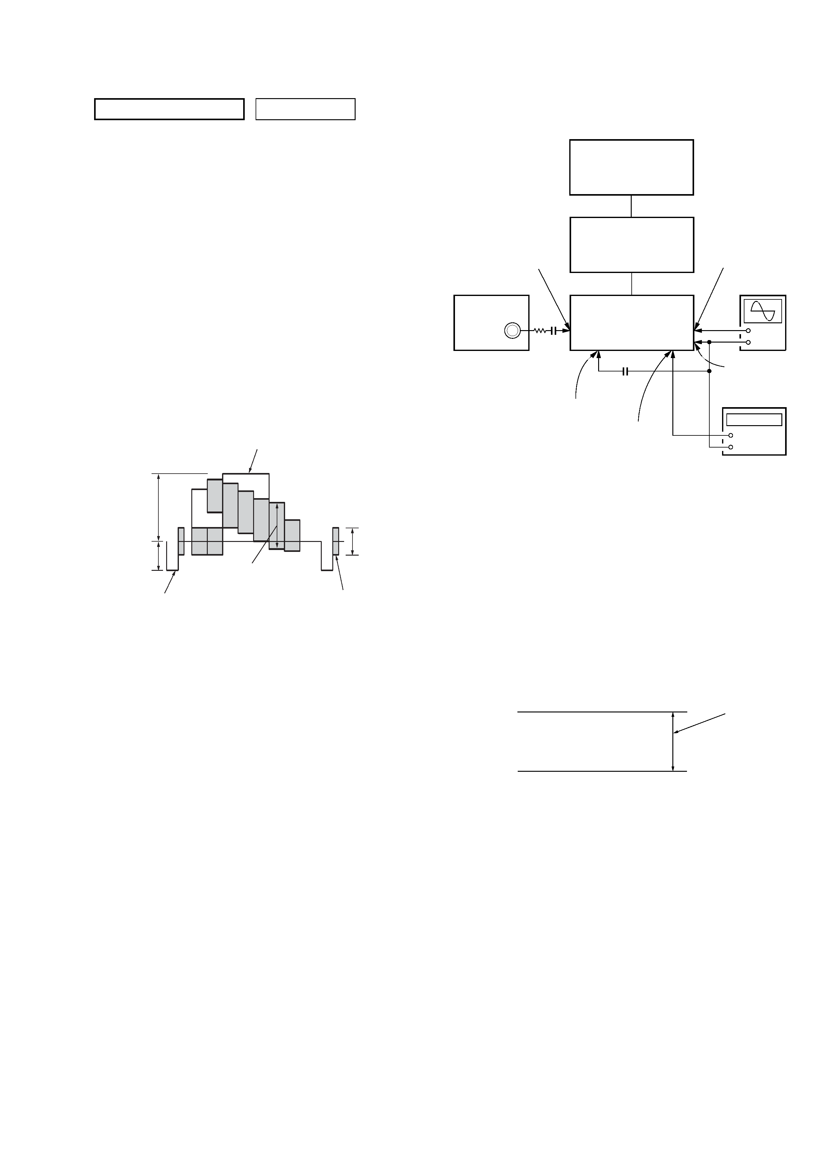
TV SSG COLOR BAR SIGNAL
White (Approx. 100%)
Approx.
0.3 V
Approx.
0.3 V
Approx.
0.7 V
Burst signal
(Must be flat)
Red
Horizontal sync signal
PIF ADJUSTMENT (45.75MHz)
Connection:
Adjusting Method:
1. Connect the TV SSG to the TP109 (IF) on the HIDE board.
2. Connect the oscilloscope to the TP132 (PIF) on the HIDE
board.
3. Connect the TP42 (RF2) and TP60 (GND) on the HIDE board
with a capacitor to place the TV tuner unit (TV100) in the
non-signal state.
4. Connect the regulated power supply to the TP142 (2AGC) and
apply +5.5 V.
5. Adjust the receiving channel of the set to an idle channel where
there is no broadcasting station.
6. Adjust the T106 on the HIDE board so that the DC level of the
waveform on the oscilloscope becomes the lowest.
Note: After the PIF adjustment, be sure to perform the following.
Adjusting and Checking Location: HIDE Board (see page 7)
+
Oscilloscope
TV SSG
100
0.01 µF
0.01 µF
TP109 (IF)
Frequency :
45.75 MHz
No modulation
Output level :
58 dBµV
Regulated
power supply
+5.5 V
TP60 (GND)
TP42 (RF2)
TP142 (2AGC)
TP132 (PIF)
TV Tuner Unit
(XT-63V)
+
Connection Box
(XA-114)
Media Center Main Unit
(XAV-7W)
DC level
(lowest)
0V