SERVICE MANUAL
Model Name Using Similar Mechanism
XR-C5300X/C5600X
Tape Transport Mechanism Type
MG-25F-136
FM/AM CASSETTE CAR STEREO
US Model
Canadian Model
XR-CA600X
E Model
XR-CA620X
SPECIFICATIONS
XR-CA600X/CA620X
Photo: XR-CA600X
Ver 1.1 2001.05
9-870-248-12
Sony Corporation
2001E0500-1
e Vehicle Company
C
2001.5
Shinagawa Tec Service Manual Production Group
Cassette Player section
Tape track
4-track 2-channel stereo
Wow and flutter
0.08 % (WRMS)
Frequency response
30 18,000 Hz
Signal-to-noise ratio
Tuner section
FM
T
XR-CA600X:
XR-CA620X:
uning range
FM tuning interval:
50 kHz/200 kHz switchable
87.5 108.0 MHz
(at 50 kHz step)
87.5 107.9 MHz
87.5 107.9 MHz
(at 200 kHz step)
Aerial terminal
External aerial connector
Intermediate frequency
10.7 MHz/450 kHz
Usable sensitivity
8 dBf
Selectivity
75 dB at 400 kHz
Signal-to-noise ratio
66 dB (stereo),
72 dB (mono)
Harmonic distortion at 1 kHz
0.6 % (stereo),
0.3 % (mono)
Separation
35 dB at 1 kHz
Frequency response
30 15,000 Hz
MW (XR-CA620X)
Tuning range
MW tuning interval:
9 kHz/10 kHz switchable
531 1,602 kHz
(at 9 kHz step)
530 1,710 kHz
(at 10 kHz step)
SW (XR-CA620X)
Tuning range
SW tuning interval:
SW1: 2,940 7,735 kHz
SW2: 9,500 18,135 kHz
(except for 10,140 11,575
kHz)
Aerial terminal
External aerial connector
Intermediate frequency
10.7 MHz/450 kHz
Sensitivity
30
µV (at MW)
40
µV (at SW)
Power amplifier section
Outputs
Speaker outputs
(sure seal connectors)
Speaker impedance
4 8 ohms
Maximum power output
50 W
× 4 (at 4 ohms)
General
Outputs
Audio outputs
Power aerial relay control
lead
Power amplifier control lead
Inputs
BUS control input
connector
BUS audio input connector
Remote controller input
connector
Aerial input connector
Tone controls
Bass
±8 dB at 100 Hz
Treble
±8 dB at 10 kHz
Loudness
100 Hz +8 dB
10 kHz +2 dB
Power requirements
12 V DC car battery
(negative earth)
Dimensions
Approx. 178
× 50 × 176
mm (w/h/d)
Mounting dimensions
Approx. 182
× 53 × 161
mm (w/h/d)
Mass
Approx. 1.2 kg
Supplied accessories
Card
(XR-CA620X only) (1)
remote commander
Parts for installation and
connections (1 set)
Front panel case (1)
Note
This unit cannot be connected to a digital preamplifier
or an equalizer.
Design and specifications are subject to change
without notice.
Cassette type
TYPE II, IV
61 dB
TYPE I
58 dB
AUDIO POWER SPECIFICATIONS (US model only)
POWER OUTPUT AND TOTAL HARMONIC DISTORTION
23 watts per channel minimum continuous average power into 4 ohms, 4 channels
driven from 20 Hz to 20 kHz with no more than 5% total harmonic distortion.
AM (XR-CA600X)
Tuning range
530 1,710 kHz
Antenna terminal
External antenna connector
Intermediate frequency
10.7 MHz/450 kHz
Sensitivity
30
µV

2
XR-CA600X/CA620X
TABLE OF CONTENTS
1.
GENERAL
Location of Controls .......................................................
3
Setting the Clock .............................................................
5
2.
DISASSEMBLY
2-1. Disassembly Flow ...........................................................
9
2-2. Sub Panel Assy ................................................................
9
2-3. Mechanism Deck (MG-25F-136) ................................... 10
2-4. MAIN Board ................................................................... 10
2-5. Heat Sink (2P) ................................................................. 11
3.
ASSEMBLY OF MECHANISM DECK
3-1. Housing ........................................................................... 12
3-2. Arm (Suction) ................................................................. 12
3-3. Lever (LDG-A)/(LDG-B) ............................................... 13
3-4. Gear (LDG-FT) ............................................................... 13
3-5. Guide (C) ......................................................................... 14
3-6. Mounting Position of Capstan/reel Motor (M901) ........ 14
4.
MECHANICAL ADJUSTMENTS ....................... 15
5.
ELECTRICAL ADJUSTMENTS
Tape Deck Section .......................................................... 15
Tuner Section .................................................................. 15
6.
DIAGRAMS
6-1. Note for Printed Wiring Boards and
Schematic Diagrams ....................................................... 15
6-2. Printed Wiring Board MAIN Board ......................... 16
6-3. Schematic Diagram MAIN Board (1/3) ................... 17
6-4. Schematic Diagram MAIN Board (2/3) ................... 18
6-5. Schematic Diagram MAIN Board (3/3) ................... 19
6-6. Printed Wiring Board SUB Board ............................ 20
6-7. Schematic Diagram SUB Board ............................... 20
6-8. Printed Wiring Board KEY Board ............................ 22
6-9. Schematic Diagram KEY Board .............................. 23
6-10. IC Pin Function Description ........................................... 24
7.
EXPLODED VIEWS
7-1. General Section ............................................................... 26
7-2. Front Panel Section ......................................................... 27
7-3. Mechanism Deck Section (MG-25F-136) ...................... 28
8.
ELECTRICAL PARTS LIST ............................... 29
Notes on chip component replacement
· Never reuse a disconnected chip component.
· Notice that the minus side of a tantalum capacitor may be dam-
aged by heat.
Flexible Circuit Board Repairing
· Keep the temperature of the soldering iron around 270 °C dur-
ing repairing.
· Do not touch the soldering iron on the same conductor of the
circuit board (within 3 times).
· Be careful not to apply force on the conductor when soldering
or unsoldering.
3
XR-CA600X/CA620X
SECTION 1
GENERAL
This section is extracted from
instruction manual.
4
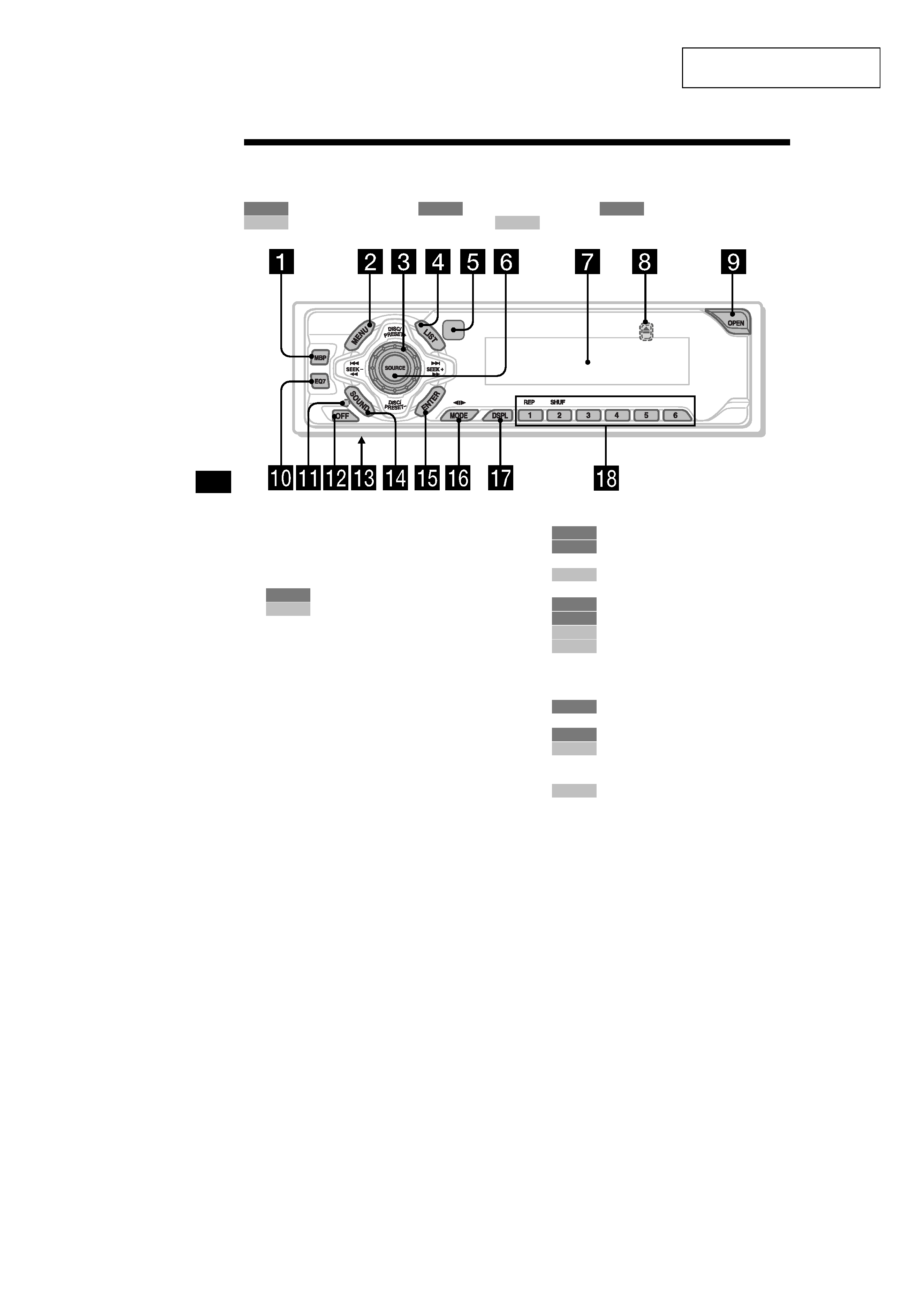
Location of controls
Refer to the pages listed for details.
: During tape playback
: During radio reception
: During menu mode
: During CD/MD playback (optional)
: During TV reception (optional)
a MBP button 16
b MENU button 8, 9, 10, 11, 12, 15, 16,
17, 19, 20, 21, 22
c Volume control dial
d LIST button
11, 12
19, 20
e Receptor for the card remote
commander
f SOURCE (Power on/Tape/Radio/CD/
MD/TV) button 5, 9, 10, 11, 16, 17, 19,
21, 22, 23
g Display window
h Z (eject) button (located on the front side
of the unit, behind the front panel) 9, 23
i OPEN button 7, 9
j EQ7 button 16
k RESET button (located on the front side of
the unit, behind the front panel) 7
l OFF (Stop/Power off) button* 5, 7, 9,
17
m Frequency select switch (located on
th
(XR-CA620X only)
e bottom of the unit)
See "Frequency select switch" in the
Installation/Connections manual.
n SOUND button 14, 16
o ENTER button
12
8, 9, 10, 11, 12, 15, 16, 17, 19,
20, 21, 22, 23
19, 20
p MODE (o) button
9
10, 11
17, 19
21
q DSPL (display mode change) button
12, 18, 19
r Number buttons
(1)
REP 9
10, 11
(1)
REP 18
(2)
SHUF 18
22
* Warning when installing in a car without
an ACC (accessory) position on the
ignition switch
After turning off the ignition, be sure to press
(OFF)
on the unit for 2 seconds to turn off the
clock display.
Otherwise, the clock display does not turn off and
this causes battery drain.
TAPE
RADIO
MENU
CD/MD
TV
RADIO
CD/MD
RADIO
MENU
CD/MD
TAPE
RADIO
CD/MD
TV
TAPE
RADIO
CD/MD
TV
4
XR-CA600X/CA620X
5
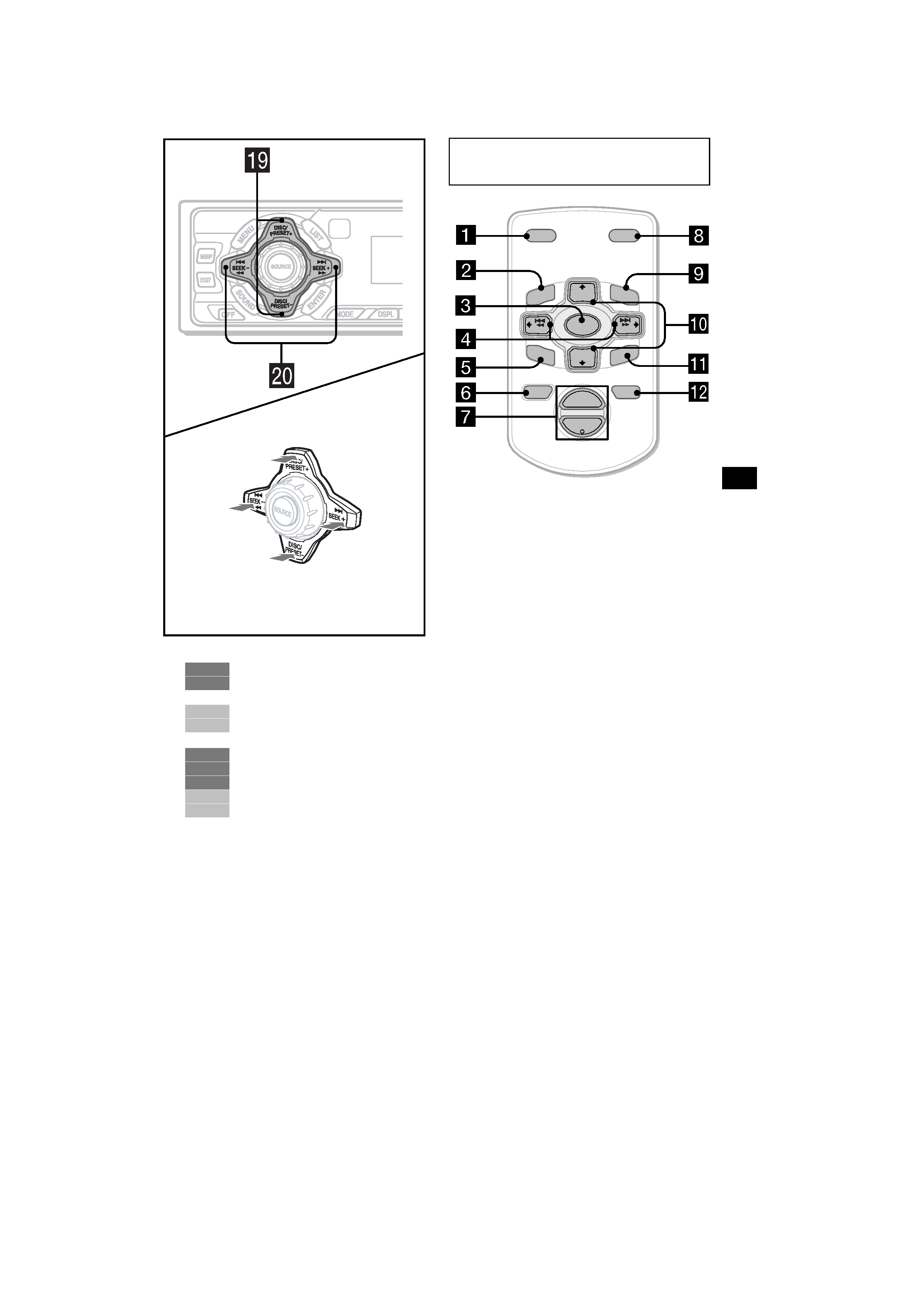
s DISC/PRESET buttons (+/)
10, 11, 12
8, 9, 10, 11, 12, 15, 16, 17, 19,
20, 21, 22
17, 19, 20
21
t SEEK buttons (/+)
9
10, 11
8, 9, 14, 15, 16, 17, 21
17, 19, 20
22, 23
The corresponding buttons of the card
remote commander control the same
functions as those on this unit.
a DSPL button
b MENU button
c SOURCE button
d SEEK (</,) buttons
e SOUND button
f OFF button
g VOL (/+) buttons
h MODE button
i LIST button
j DISC/PRESET(M/m) buttons
k ENTER button
l ATT button
Note
If the units is turned off by pressing (OFF) for 2
seconds, it cannot be operated with the card remote
commander unless (SOURCE) on the unit is pressed,
or a cassette is inserted to activate the unit first.
Tip
Refer to "Replacing the lithium battery" for details on
how to replace the batteries (page 24).
(SEEK)
(): to select
leftwards/
.
(SEEK)
(+): to select
rightwards/
>
(DISC/PRESET)
(+): to select upwards
In menu mode, the currently selectable button (s)
of these four are indicated with a " M" in the display.
(DISC/PRESET)
(): to select downwards
RADIO
MENU
CD/MD
TV
TAPE
RADIO
MENU
CD/MD
TV
Card remote commander RM-X114
(XR-CA620X only)
DISC
ATT
OFF
DSPL
MODE
SOURCE
DISC +
VOL
+
PRESET +
SEEK+
SEEK
PRESET
SOUND
ENTER
MEN
U
LIST
5
XR-CA600X/CA620X
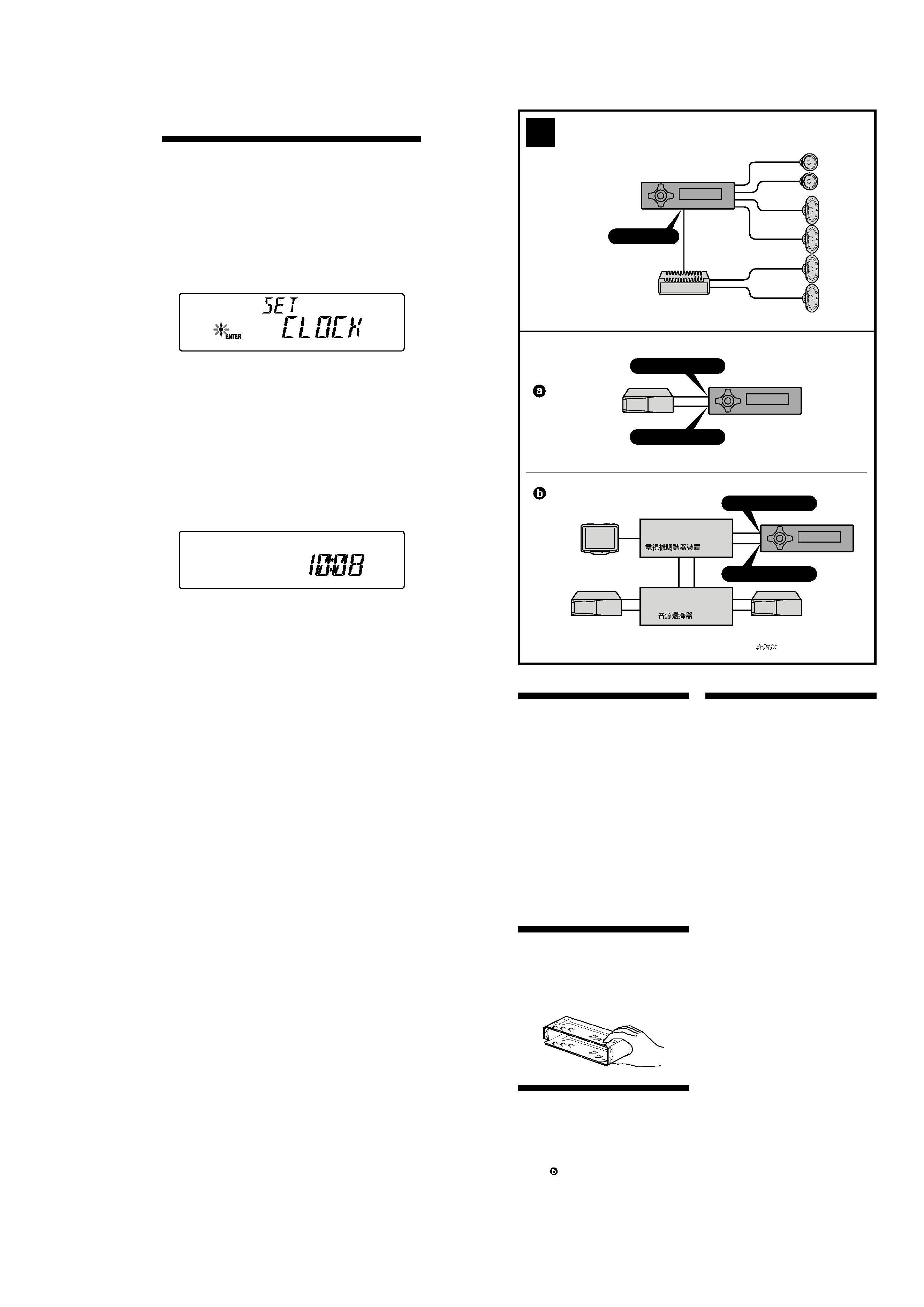
Setting the clock
The clock uses a 12-hour digital indication.
Example: To set the clock to 10:08
1 Press (MENU), then press either side
of (DISC/PRESET) repeatedly until
"CLOCK" appears.
1Press (ENTER).
The hour indication flashes.
2Press either side of (DISC/PRESET)
to set the hour.
3Press the (+) side of (SEEK).
The minute indication flashes.
4Press either side of (DISC/PRESET)
to set the minute.
2 Press (ENTER).
The clock starts. After the clock setting is
completed, the display returns to normal play
mode.
Tip
When D.INFO mode is set to ON, the time is always
displayed (page 15).
Cautions
· This unit is designed for negative earth 12 V
DC operation only.
· Do not get the wires under a screw, or caught
in moving parts (e.g. seat railing).
· Before making connections, disconnect the
earth terminal of the car battery to avoid short
circuits.
· Connect the yellow and red power input leads
only after all other leads have been connected.
· Run all earth wires to a common earth
point.
· Be sure to insulate any loose unconnected
wires with electrical tape for safety.
Notes on the power supply cord (yellow)
· When connecting this unit in combination with
other stereo components, the connected car
circuit's rating must be higher than the sum of
each component's fuse.
· When no car circuits are rated high enough,
connect the unit directly to the battery.
Parts Iist (
1)
The numbers in the list are keyed to those in the
instructions.
Caution
Handle the bracket 1 carefully to avoid injuring
your fingers.
Connection example (
2)
Notes (
2-A)
· Be sure to connect the earth cord before
connecting the amplifier.
· If you connect an optional power amplifier and do
not use the built-in amplifier, the beep sound will
be deactivated.
Tip (
2-B- )
For connecting two or more changers, the source
selector XA-C30 (optional) is necessary.
Connection diagram (
3)
1 To a metal surface of the car
First connect the black earth lead, then connect
the yellow and red power input leads.
2 To the power aerial control lead or power
supply lead of aerial booster amplifier
Notes
· It is not necessary to connect this lead if there
is no power aerial or aerial booster, or with a
manually-operated telescopic aerial.
· When your car has a built-in FM/MW/SW aerial
in the rear/side glass, see "Notes on the control
and power supply leads."
3 To AMP REMOTE IN of an optional power
amplifier
This connection is only for amplifiers. Connecting
any other system may damage the unit.
4 To the +12 V power terminal which is energised
in the accessory position of the ignition key
switch
Notes
· If there is no accessory position, connect to the
+12 V power (battery) terminal which is
energised at all times.
Be sure to connect the black earth to it first.
· When your car has a built-in FM/MW/SW aerial
in the rear/side glass, see "Notes on the control
and power supply leads."
5 To the +12 V power terminal which is energised
at all times
Be sure to connect the black earth lead to it first.
Notes on the control and power supply leads
· The power aerial control lead (blue) supplies +12 V
DC when you turn on the tuner.
· When your car has built-in FM/MW/SW aerial in
the rear/side glass, connect the power aerial
control lead (blue) or the accessory power input
lead (red) to the power terminal of the existing
aerial booster. For details, consult your dealer.
· A power aerial without relay box cannot be used
with this unit.
Memory hold connection
When the yellow power input lead is connected,
power will always be supplied to the memory circuit
even when the ignition key is turned off.
Notes on speaker connection
· Before connecting the speakers, turn the unit off.
· Use speakers with an impedance of 4 to 8 ohms,
and with adequate power handling capacities to
avoid its damage.
· Do not connect the speaker terminals to the car
chassis, or connect the terminals of the right
speakers with those of the left speaker.
· Do not connect the earth lead of this unit to the
negative () terminal of the speaker.
· Do not attempt to connect the speakers in parallel.
· Connect only passive speakers. Connecting active
speakers (with built-in amplifiers) to the speaker
terminals may damage the unit.
2
B
BUS AUDIO IN
BUS CONTROL IN
TV tuner unit
Syntoniseur de télévision
BUS CONTROL IN
BUS AUDIO IN
A
AUDIO OUT
Source selector
Selector de fuente
*
*
*not supplied
no suministrado