MICROFILM
SERVICE MANUAL
FM/MW/LW CASSETTE CAR STEREO
AEP Model
UK Model
Model Name Using Similar Mechanism
XR-C8100R
Tape Transport Mechanism Type
MG-25D-136
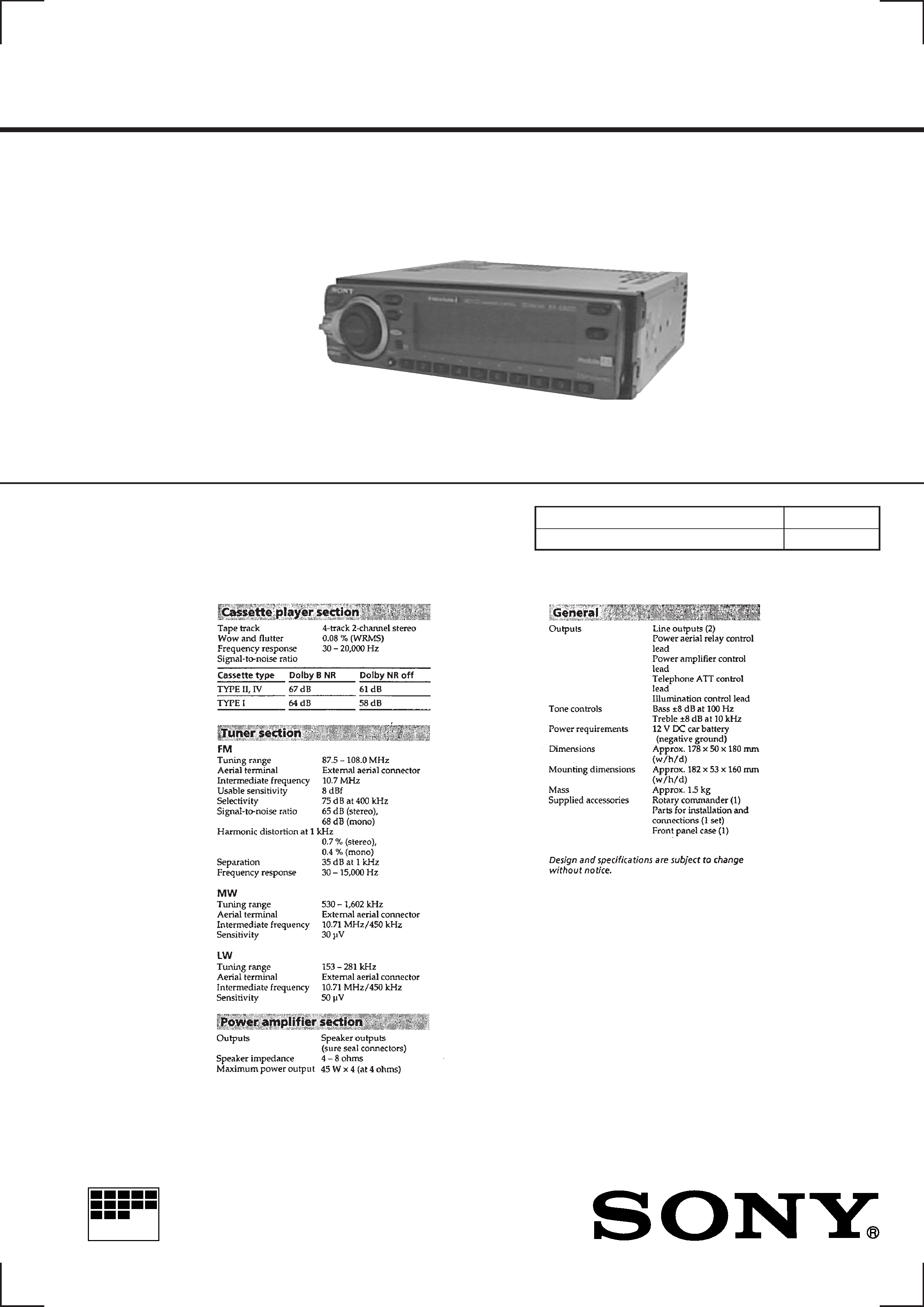
SPECIFICATIONS
XR-C8220R
For RM-X4S (Remote Commander),
please refer to RM-X4S Service Manual
(9-925-698-
) previously issued.
Dolby noise reduction manufactured under license
from Dolby Laboratories Licensing Corporation.
"DOLBY" and the double-D symbol
a are trade-
marks of Dolby Laboratories Licensing Corporation.
2
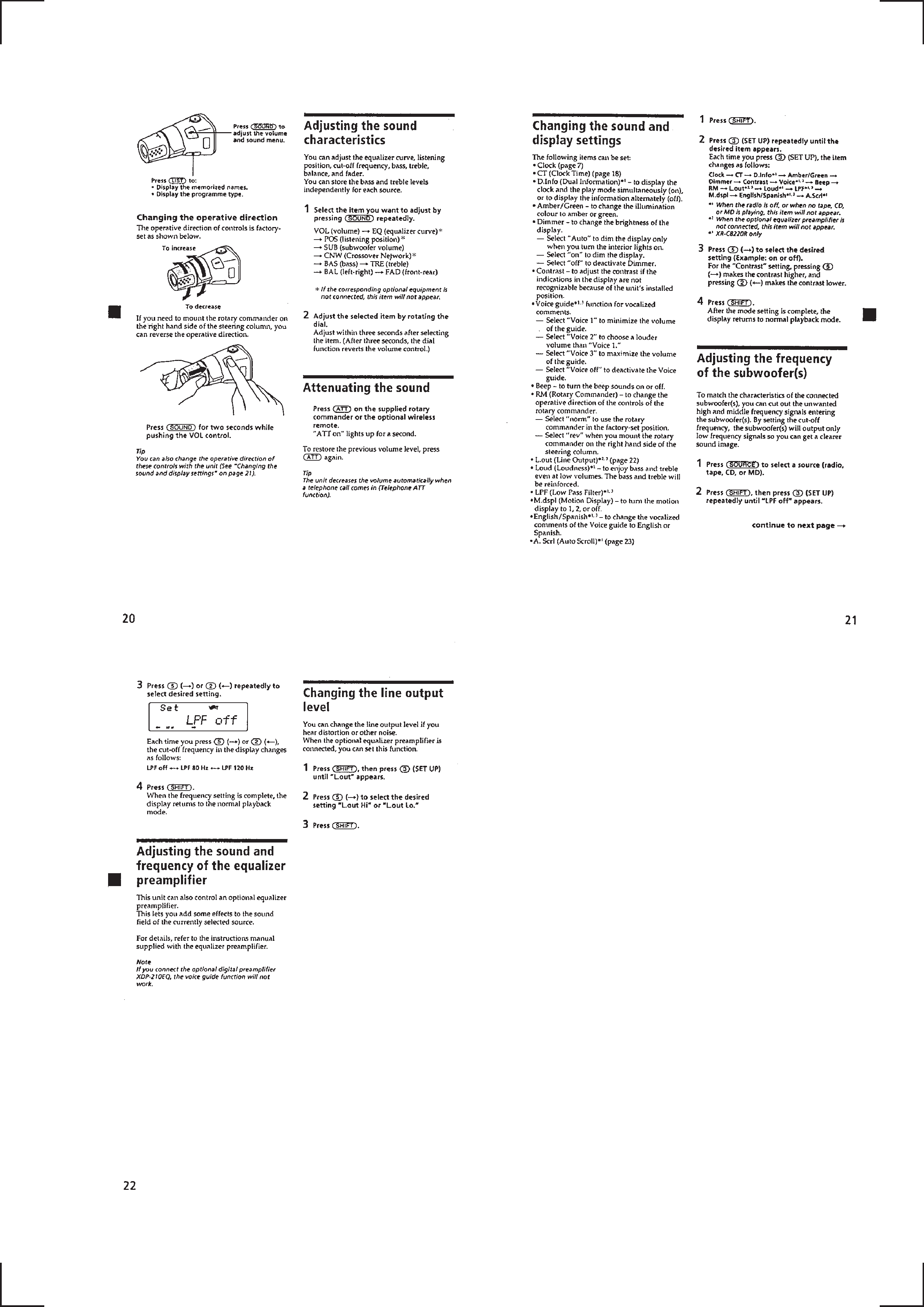
Flexible Circuit Board Repairing
· Keep the temperature of the soldering iron around 270 °C dur-
ing repairing.
· Do not touch the soldering iron on the same conductor of the
circuit board (within 3 times).
· Be careful not to apply force on the conductor when soldering
or unsoldering.
Notes on chip component replacement
· Never reuse a disconnected chip component.
· Notice that the minus side of a tantalum capacitor may be dam-
aged by heat.
TABLE OF CONTENTS
1.
SERVICE NOTE ....................................................... 2
2.
GENERAL
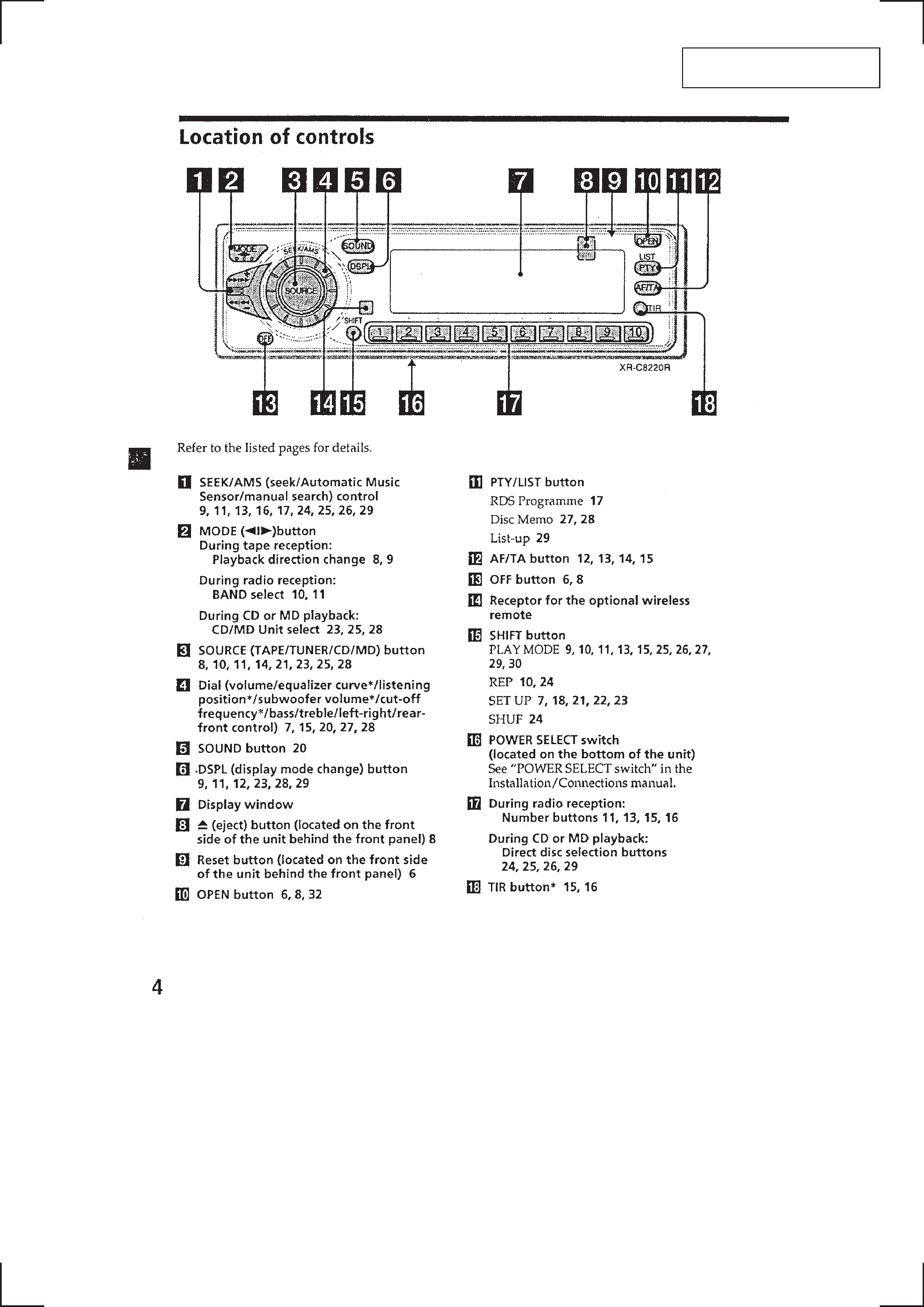
Location of Controls .......................................................
3
Resetting the Unit ...........................................................
4
Setting the Clock .............................................................
4
Other Functions ...............................................................
4
Installation .......................................................................
6
Connections .....................................................................
7
3.
DISASSEMBLY ......................................................... 12
4.
ASSEMBLY OF MECHANISM DECK ........... 14
5.
MECHANICAL ADJUSTMENTS ....................... 17
6.
ELECTRICAL ADJUSTMENTS
Test Mode ........................................................................ 18
Tape Deck Section .......................................................... 18
Tuner Section .................................................................. 19
7.
DIAGRAMS
7-1. Block Diagram TUNER Section .............................. 23
7-2. Block Diagram TAPE Section .................................. 25
7-3. Block Diagram MAIN Section ................................. 27
7-4. Block Diagram
DISPLAY/KEY CONTROL Section ........................ 29
7-5. Block Diagram
BUS CONTROL/POWER SUPPLY Section ........... 31
7-6. Note for Printed Wiring Boards and
Schematic Diagrams ....................................................... 33
7-7. Printed Wiring Board
MAIN Board (Component Side) .............................. 35
7-8. Printed Wiring Board
MAIN Board (Conductor Side) ................................ 37
7-9. Schematic Diagram MAIN Board (1/4) ................... 39
7-10. Schematic Diagram MAIN Board (2/4) ................... 41
7-11. Schematic Diagram MAIN Board (3/4) ................... 43
7-12. Schematic Diagram MAIN Board (4/4) ................... 45
7-13. Printed Wiring Board KEY Board ............................ 47
7-14. Schematic Diagram KEY Board .............................. 49
7-15. Printed Wiring Boards SUB/INVERTER Boards .... 51
7-16. Schematic Diagram
SUB/INVERTER Boards .......................................... 52
7-17. IC Pin Function Description ........................................... 58
8.
EXPLODED VIEWS ................................................ 62
9.
ELECTRICAL PARTS LIST ............................... 65
SECTION 1
SERVICE NOTE
· Model Identification
The destination is expressed with the model according to the lan-
guage of CSV (Computer Sound Voice) mounted in the set.
How to identify the model is described below.
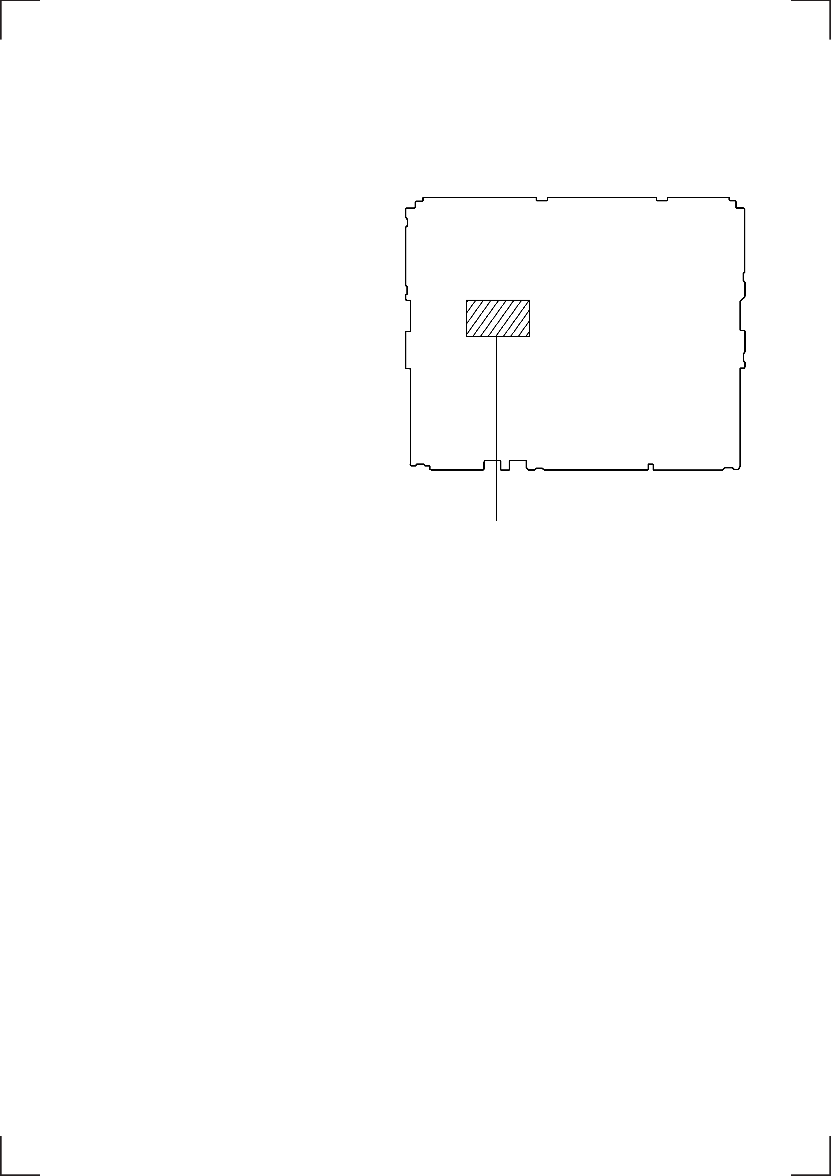
MAIN BOARD (Component Side)
IC650
MSM6656A-687GS-KR1 (TYPE A: ENGLISH, FRENCH)
MSM6656A-688GS-KR1 (TYPE B: ENGLISH, GERMAN)
MSM6656A-689GS-KR1 (TYPE C: ENGLISH, SPANISH)
MSM6656A-690GS-KR1 (TYPE D: ENGLISH, ITALIAN)
3
SECTION 2
GENERAL
This section is extracted from
instruction manual.
4
5