Model Name Using Similar Mechanism
NEW
Tape Transport Mechanism Type
MG-52A-135
East European Model
SERVICE MANUAL
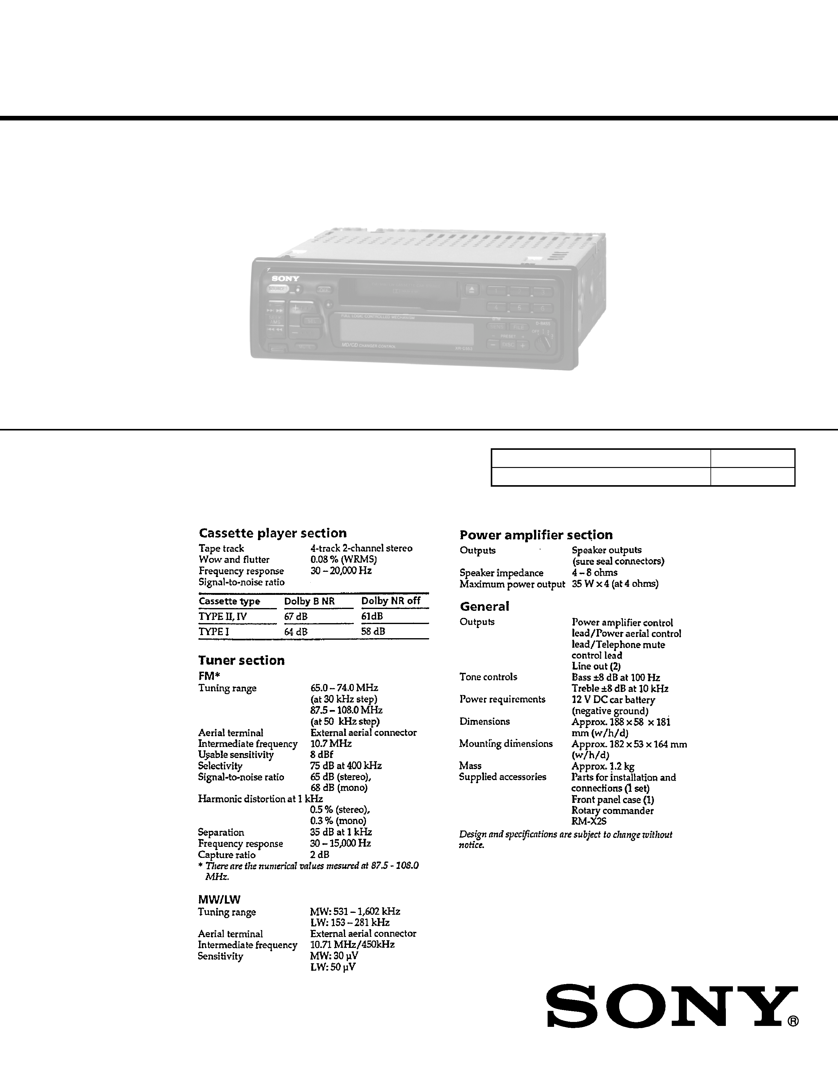
XR-C553SP
SPECIFICATIONS
Dolby noise reduction manufactured under license
from Dolby Laboratories Licensing Corporation.
"DOLBY" and the double-D symbol
a are trademarks
of Dolby Laboratories Licensing Corporation.
For RM-X2S (Remote Commander),
please reter to RM-X2S/X3S Service
Manual (9-960-039-
) previously issued.
FM/MW/LW CASSETTE CAR STEREO
Ver 1.1 2001.08
9-925-531-12
Sony Corporation
2001H0500-1
e Vehicle Company
C
2001.8
Shinagawa Tec Service Manual Production Group

2
TABLE OF CONTENTS
1.
GENERAL
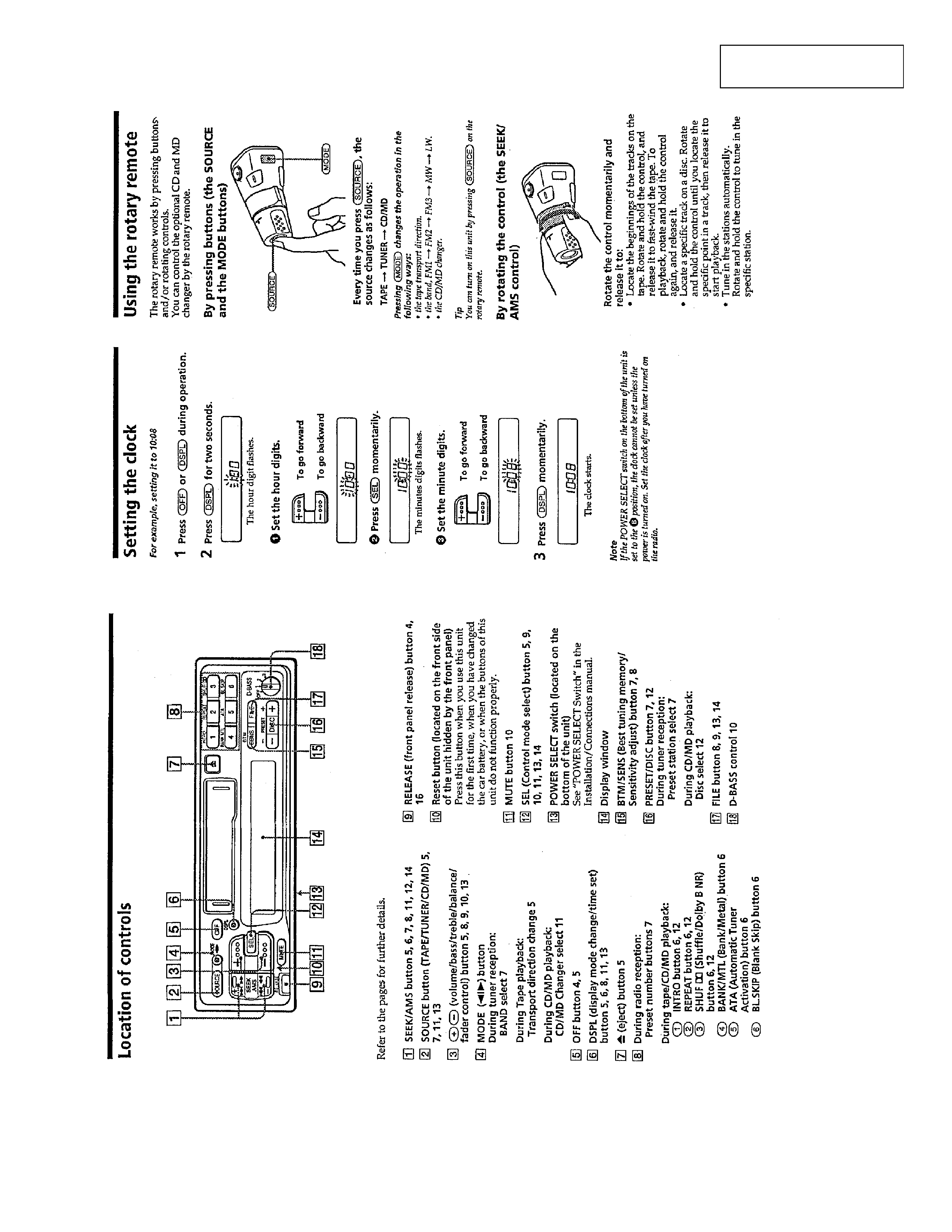
Location of Controls ..........................................................
3
Setting the Clock ...............................................................
3
Using the Rotary Remote ..................................................
3
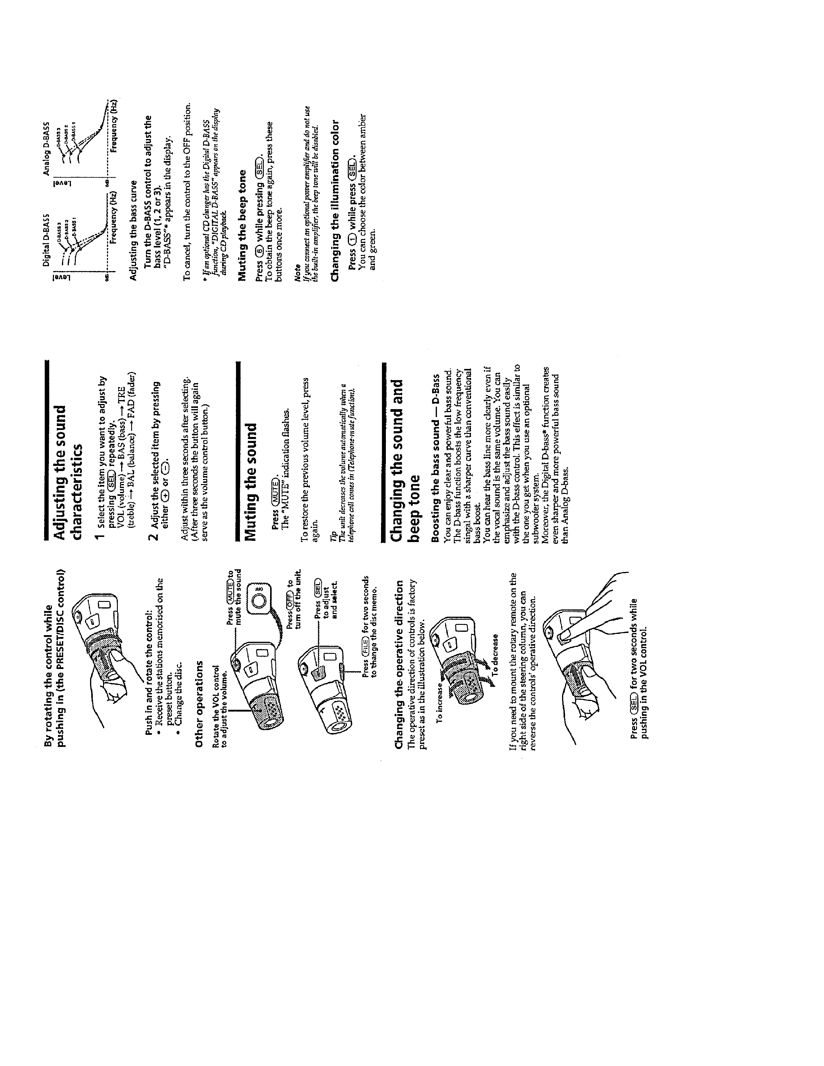
Adjusting the Sound Characteristics .................................
4
Muting the Sound ..............................................................
4
Changing the Sound and Beep Tone ..................................
4
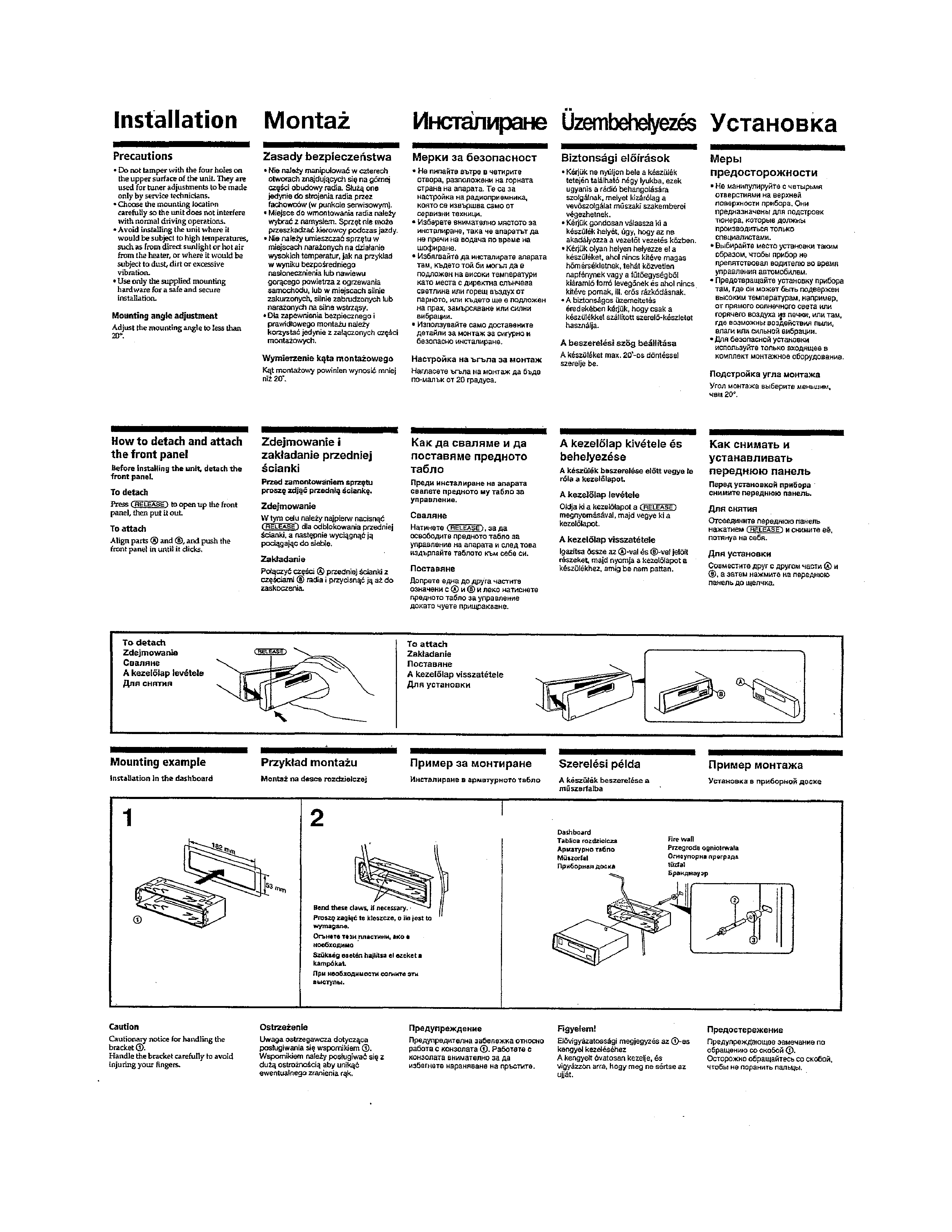
Installation .........................................................................
5
Connections .......................................................................
6
2.
DISASSEMBLY ............................................................ 9
3.
ASSEMBLY OF MECHANISM DECK ............... 11
4.
MECHANICAL ADJUSTMENTS ......................... 17
5.
ELECTRICAL ADJUSTMENTS
Test Mode .......................................................................... 17
Tape Deck Section ............................................................. 17
Tuner Section ..................................................................... 18
6.
DIAGRAMS
6-1. IC Pin Function Description .............................................. 22
6-2. Block Diagram (1/2) .......................................................... 25
6-3. Block Diagram (2/2) .......................................................... 27
6-4. Printed Wiring Boards Main Section ............................ 29
6-5. Schematic Diagram Main Section ................................ 33
6-6. Printed Wiring Board Display Section ......................... 37
6-7. Schematic Diagram Display Section ............................ 39
7.
EXPLODED VIEWS .................................................. 44
8.
ELECTRICAL PARTS LIST .................................. 48
SERVICING NOTES
Flexible Circuit Board Repairing
· Keep the temperature of the soldering iron around 270 ° C during
repairing.
· Do not touch the soldering iron on the same conductor of the
circuit board (within 3 times).
· Be careful not to apply force on the conductor when soldering or
unsoldering .
Notes on chip component replacement
· Never reuse a disconnected chip component.
· Notice that the minus side of a tantalum capacitor may be dam-
aged by heat.
3
SECTION
1
GENERAL
This
section
is
e
xtr
acted
from
instr
uction
man
ual.
4
5