FM/MW/LW CASSETTE CAR STEREO
East European Model
Model Name Using Similar Mechanism
XR-C450RDS
Tape Transport Mechanism Type
MG-25B-136
SPECIFICATIONS
SERVICE MANUAL
XR-C453RDS
For RM-X2S (Remote Commander),
please refer to RM-X2S/X3S Service
Manual (9-960-039-S) previously issued.
Cassette player section
Tape track
4-track 2-channel stereo
Wow and flutter
0.08% (WRMS)
Frequency response
30-18,000 Hz
Signal-to-noise ratio
61 dB (TYPE II, IV)
58 dB (TYPE I)
Tuner section
FM
Tuning range
FM1, FM2: 87.5-108.0 MHz
FM3: 65.0-74.0 MHz
Antenna terminal
External antenna connector
Intermediate frequency
10.7 MHz
Usable sensitivity
8 dBf
Selectivity
75 dB at 400 kHz
Signal-to-noise ratio
63 dB (stereo)
65 dB (mono)
Harmonic distortion at 1 kHz
0.5% (stereo), 0.3% (mono)
Separation
35 dB at 1 kHz
Frequency response
30-15,000 Hz
Capture ratio
2 dB
MW/LW
Tuning range
MW: 531-1,602 kHz
LW: 153-281 kHz
Antenna terminal
External antenna connector
Intermediate frequency
10.71 MHz/450 kHz
Sensitivity
MW: 30 µV
LW: 50 µV
Power amplifier section
Outputs
Speaker outputs (sure seal connectors)
Speaker impedance
4-8 ohms
Maximum power output
35 W
× 4 (at 4 ohms)
General
Outputs
Telephone mute control lead
Power amplifier control lead
Power antenna control lead
Line out (1)
Tone controls
Bass ± 8 dB at 100 Hz
Treble ± 8 dB at 10 kHz
Power requirements
12 VDC car battery (negative ground)
Dimensions
Approx. 188
× 58 × 181 mm (w/h/d)
Mounting dimensions
Approx. 182
× 53 × 164 mm (w/h/d)
Mass
Approx. 1.2 kg
Supplied accessories
Parts for installation and connections (1 set)
Rotary commander RM-X2S (1)
Front panel case (1)
Design and specifications are subject to change without notice.
9-925-636-12
Sony Corporation
2001F0500-1
e Vehicle Company
C
2001.6
Shinagawa Tec Service Manual Production Group
Ver 1.1 2001.06

2
TABLE OF CONTENTS
1.
GENERAL
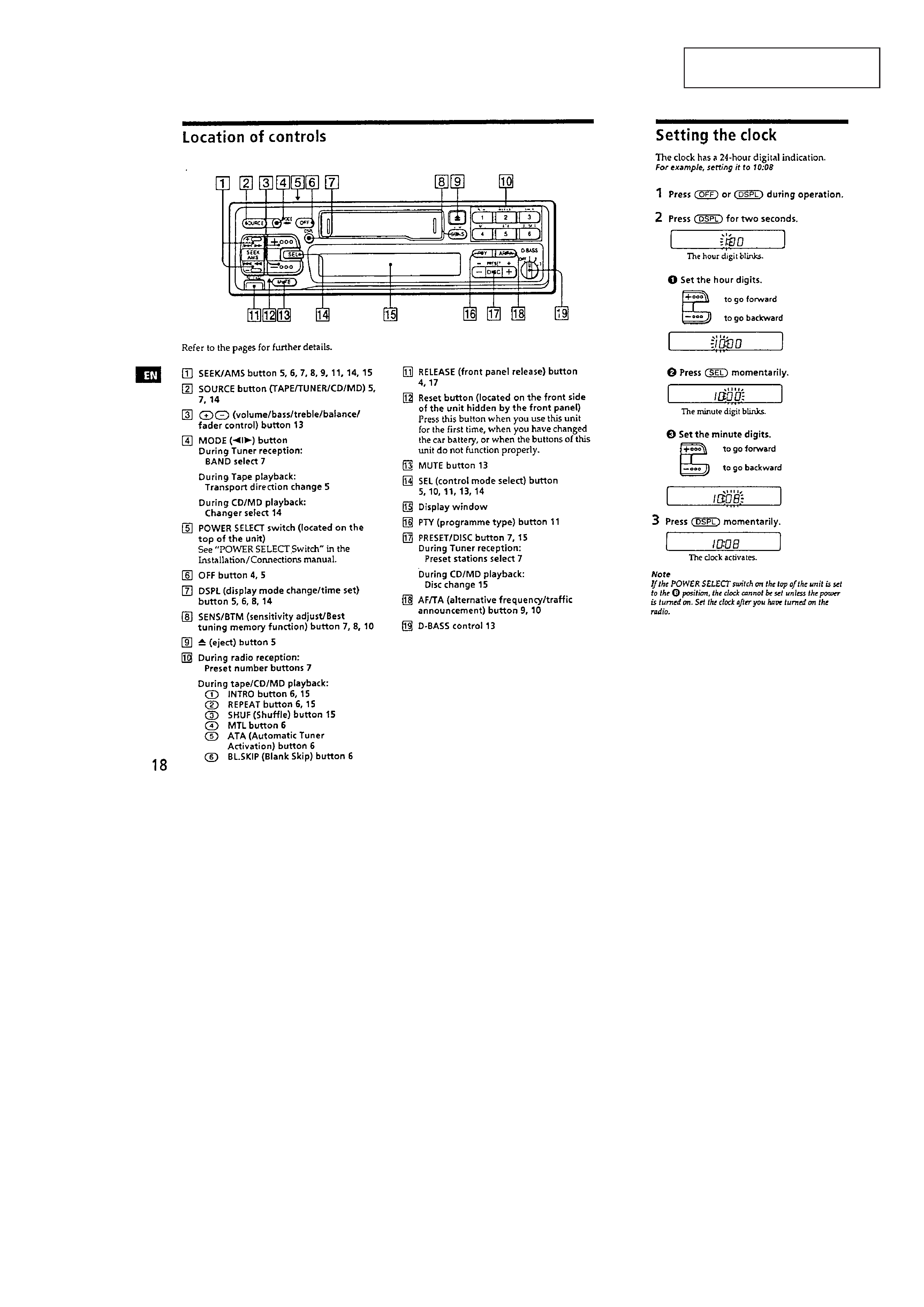
Location of Controls ........................................................ 3
Setting the Clock ............................................................. 3
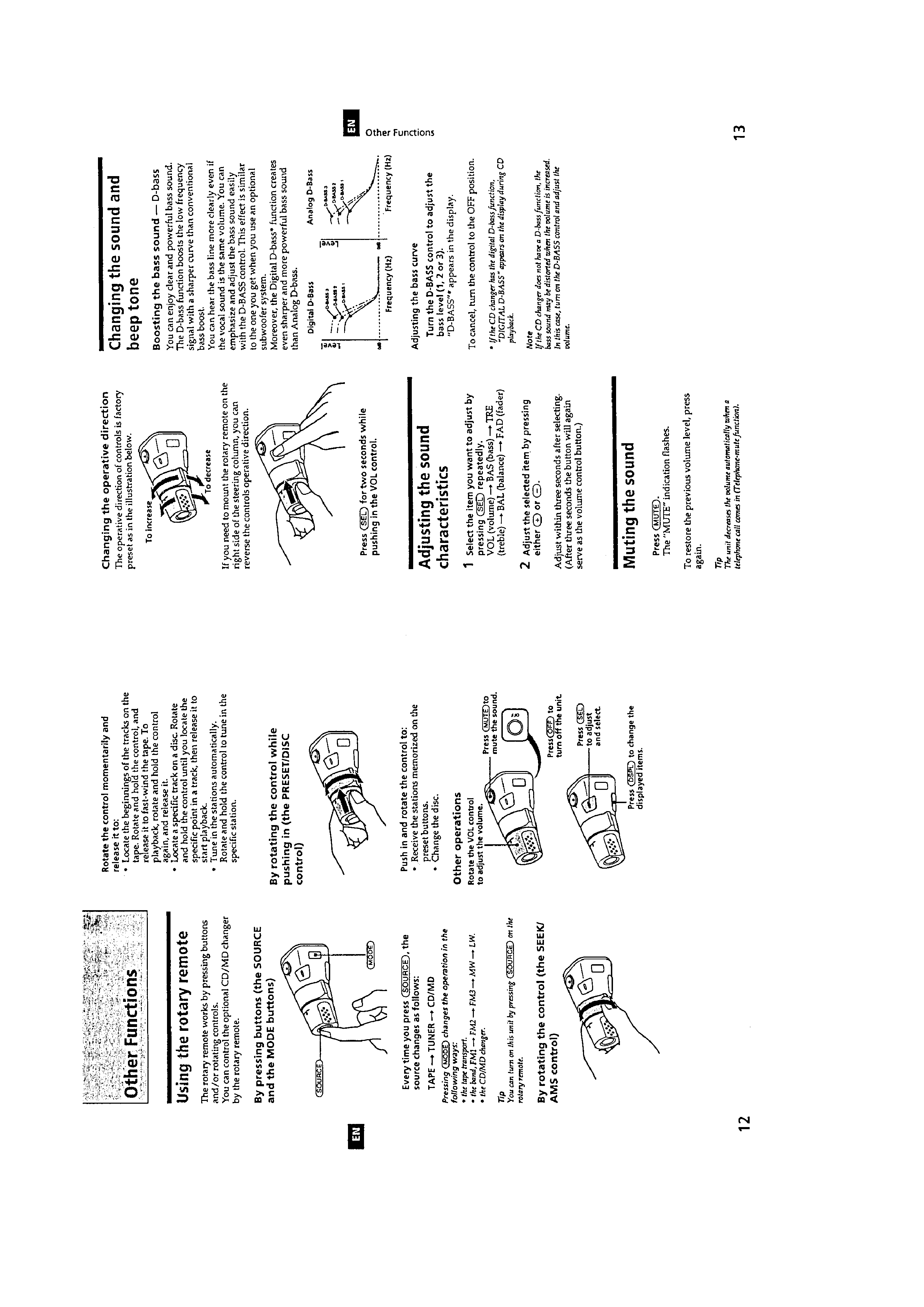
Using the Rotary Remote ................................................ 4
Adjusting the Sound Characteristics ............................... 4
Muting the Sound ............................................................ 4
Changing the Sound and Beep Tone ................................ 4
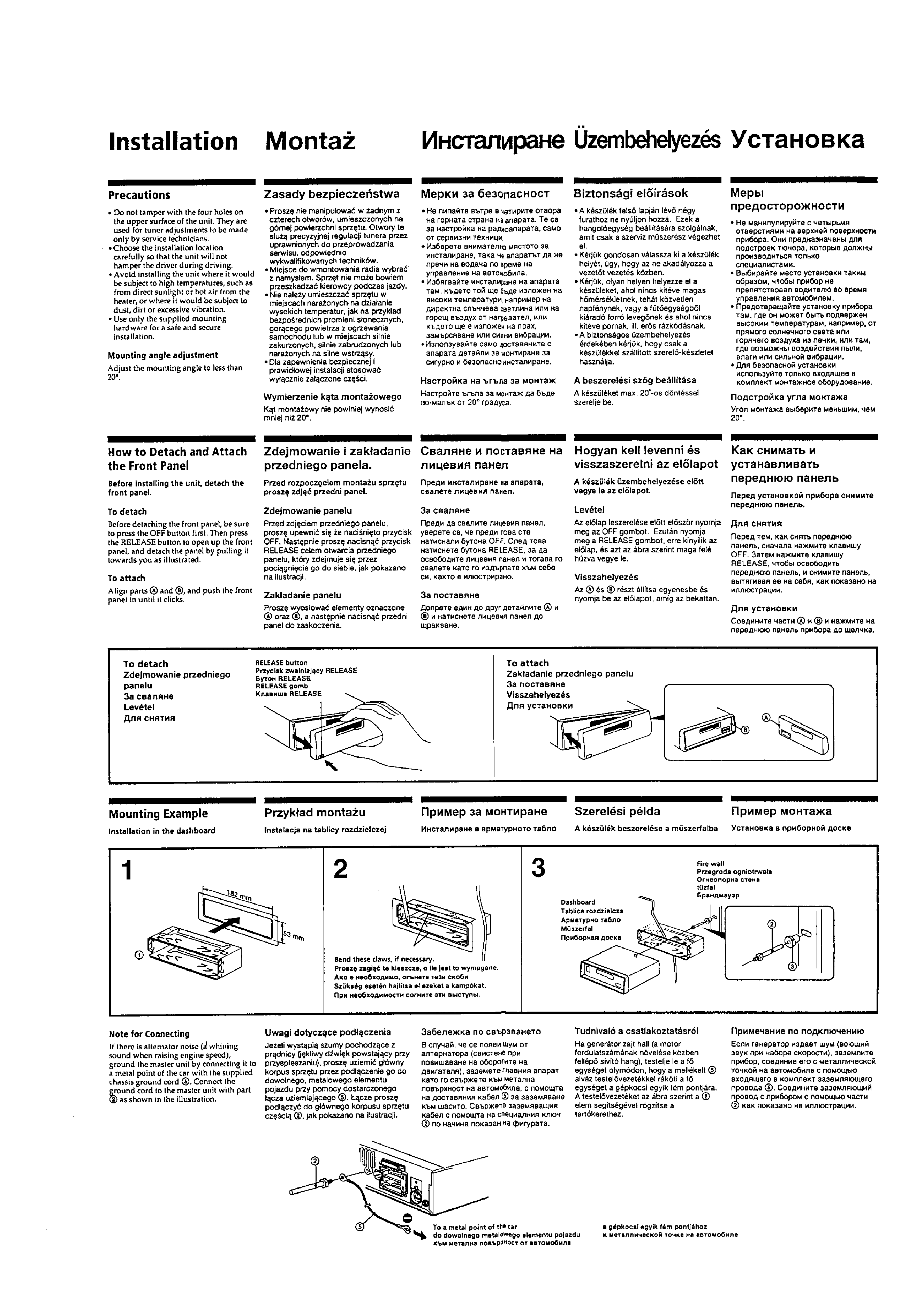
Installation ....................................................................... 5
Connections ..................................................................... 6
2.
DISASSEMBLY .......................................................... 9
3.
ASSEMBLY OF MECHANISM DECK ........... 11
4.
MECHANICAL ADJUSTMENTS ....................... 14
5.
ELECTRICAL ADJUSTMENTS
Test Mode ........................................................................ 14
Tape Deck Section ........................................................... 14
Tuner Section ................................................................... 15
6.
DIAGRAMS
6-1. Printed Wiring Board Main Section ......................... 21
6-2. Schematic Diagram Main Section (1/2) .................... 23
6-3. Schematic Diagram Main Section (2/2) .................... 27
6-4. Printed Wiring Board Power Section ........................ 29
6-5. Schematic Diagram Power Section .......................... 31
6-6. Printed Wiring Board Display Section ..................... 33
6-7. Schematic Diagram Display Section ........................ 35
6-8. IC Pin Function Description ............................................ 37
7.
EXPLODED VIEWS ................................................ 39
8.
ELECTRICAL PARTS LIST ................................ 42
SERVICING NOTES
Flexible Circuit Board Repairing
· Keep the temperature of the soldering iron around 270 °C during
repairing.
· Do not touch the soldering iron on the same conductor of the
circuit board (within 3 times).
· Be careful not to apply force on the conductor when soldering or
unsoldering
Notes on chip component replacement
· Never reuse a disconnected chip component.
· Notice that the minus side of a tantalum capacitor may be dam-
aged by heat.
3
This section is extracted from
instruction manual.
SECTION 1
GENERAL
4
5