SERVICE MANUAL
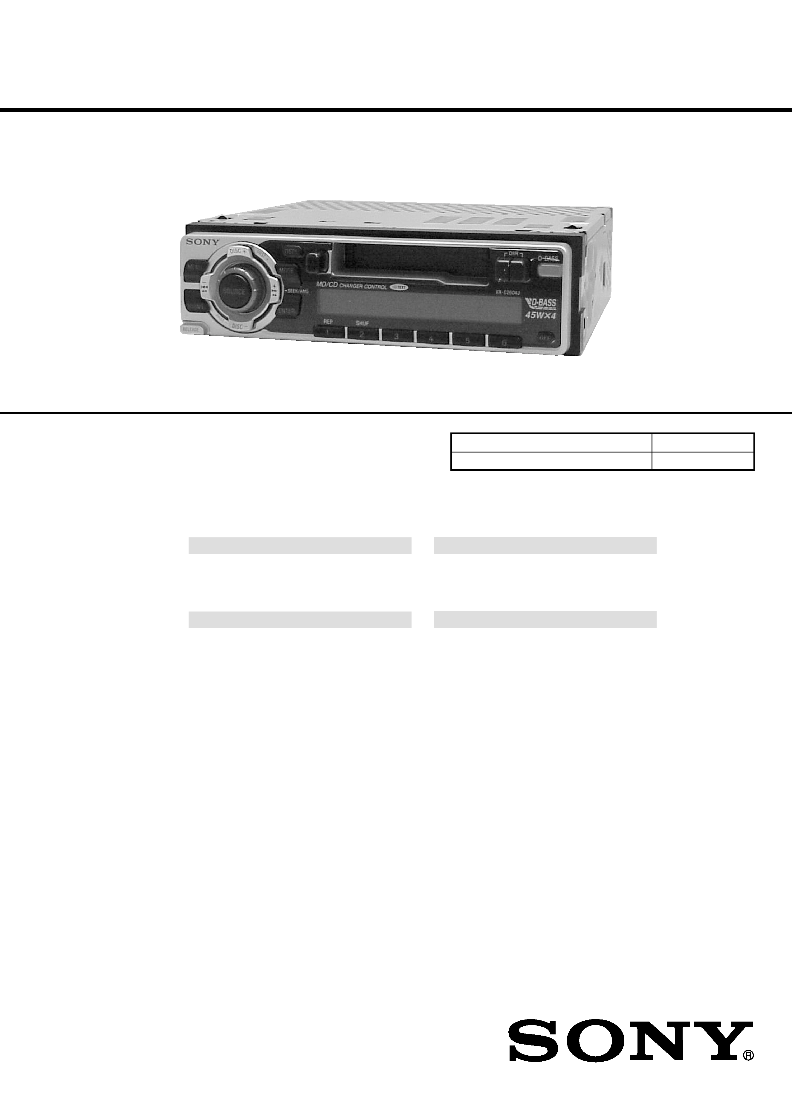
FM/MW/SW CASSETTE CAR STEREO
Saudi Arabia Model
SPECIFICATIONS
XR-C2604J
Model Name Using Similar Mechanism
XR-C2600
Tape Transport Mechanism Type
MG-36SZ10-32
Cassette player section
Tape track
4-track 2-channel stereo
Wow and flutter
0.13 % (WRMS)
Frequency response
30 15,000 Hz
Signal-to-noise ratio
55 dB
Tuner section
FM
Tuning range
87.5 108.0 MHz
Aerial terminal
External aerial connector
Intermediate frequency
10.7 MHz
Usable sensitivity
9 dBf
Selectivity
75 dB at 400 kHz
Signal-to-noise ratio
65 dB (stereo),
68 dB (mono)
Harmonic distortion at 1 kHz
0.7 % (stereo),
0.4 % (mono)
Separation
35 dB at 1 kHz
Frequency response
30 15,000 Hz
MW
Tuning range
531 1,602 kHz
SW
Tuning range
SW tuning interval:
SW1: 2,940 7,735 kHz
SW2: 9,500 18,135 kHz
(except for 10,140 11,575
kHz)
Aerial terminal
External aerial connector
Intermediate frequency
10.7 MHz/450 kHz
Sensitivity
30
µV
Power amplifier section
Outputs
Speaker outputs
(sure seal connectors)
Speaker impedance
4 8 ohms
Maximum power output 45 W
× 4 (at 4 ohms)
General
Outputs
Audio output
Power aerial relay control
lead
Power amplifier control
lead
Telephone ATT control
lead
Tone controls
Bass
±8 dB at 100 Hz
Treble
±8 dB at 10 kHz
Power requirements
12 V DC car battery
(negative earth)
Dimensions
Approx. 188
× 58 × 182 mm
(w/h/d)
Mounting dimensions
Approx. 182
× 53 × 163 mm
(w/h/d)
Mass
Approx. 1.2 kg
Supplied accessories
Parts for installation and
connections (1 set)
Front panel case (1)
Design and specifications are subject to change
without notice.

2
Flexible Circuit Board Repairing
· Keep the temperature of the soldering iron around 270 °C dur-
ing repairing.
· Do not touch the soldering iron on the same conductor of the
circuit board (within 3 times).
· Be careful not to apply force on the conductor when soldering
or unsoldering.
Notes on chip component replacement
· Never reuse a disconnected chip component.
· Notice that the minus side of a tantalum capacitor may be dam-
aged by heat.
TABLE OF CONTENTS
1.
GENERAL
Location of Controls .......................................................
3
Setting the Clock .............................................................
3
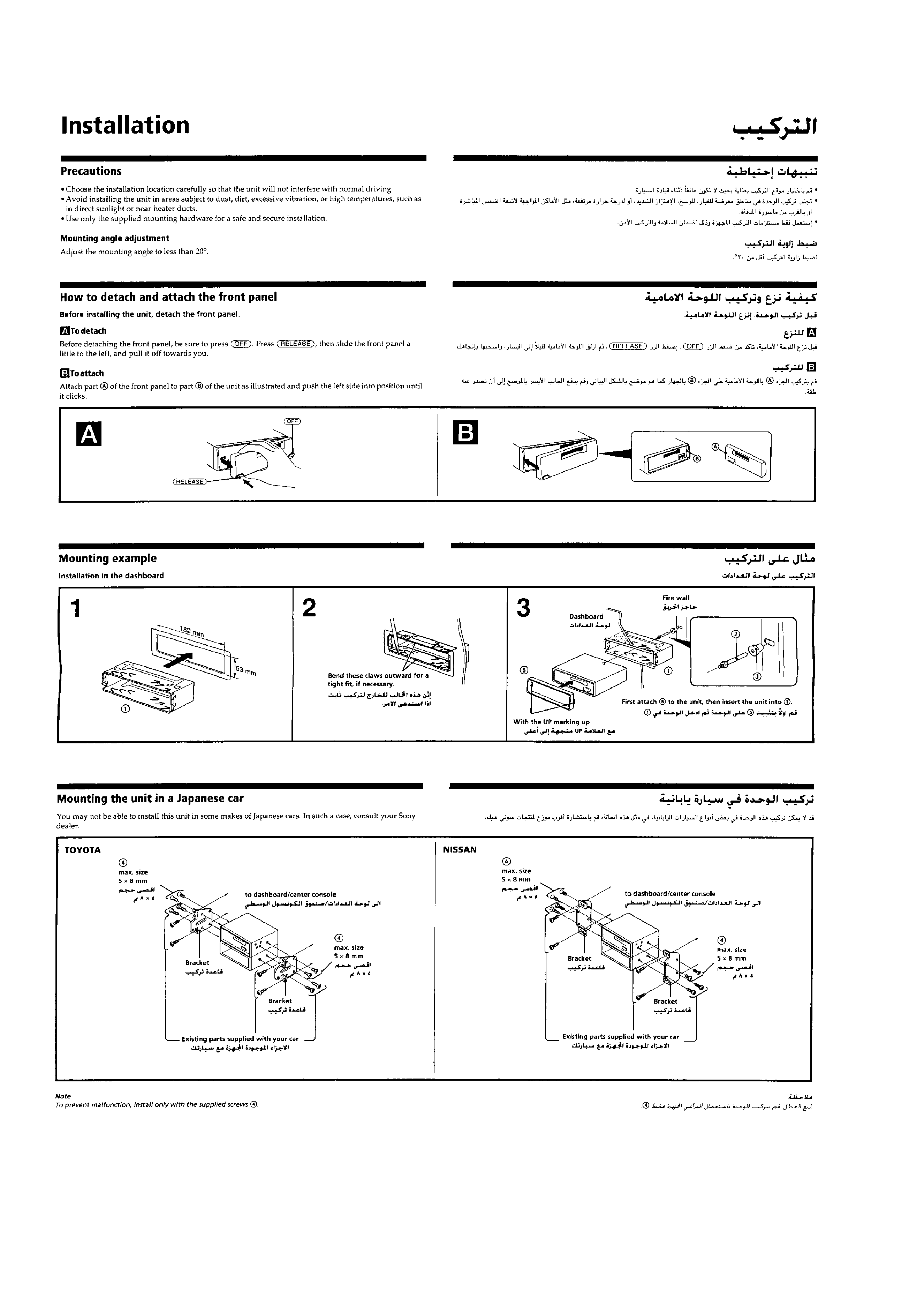
Installation .......................................................................
4
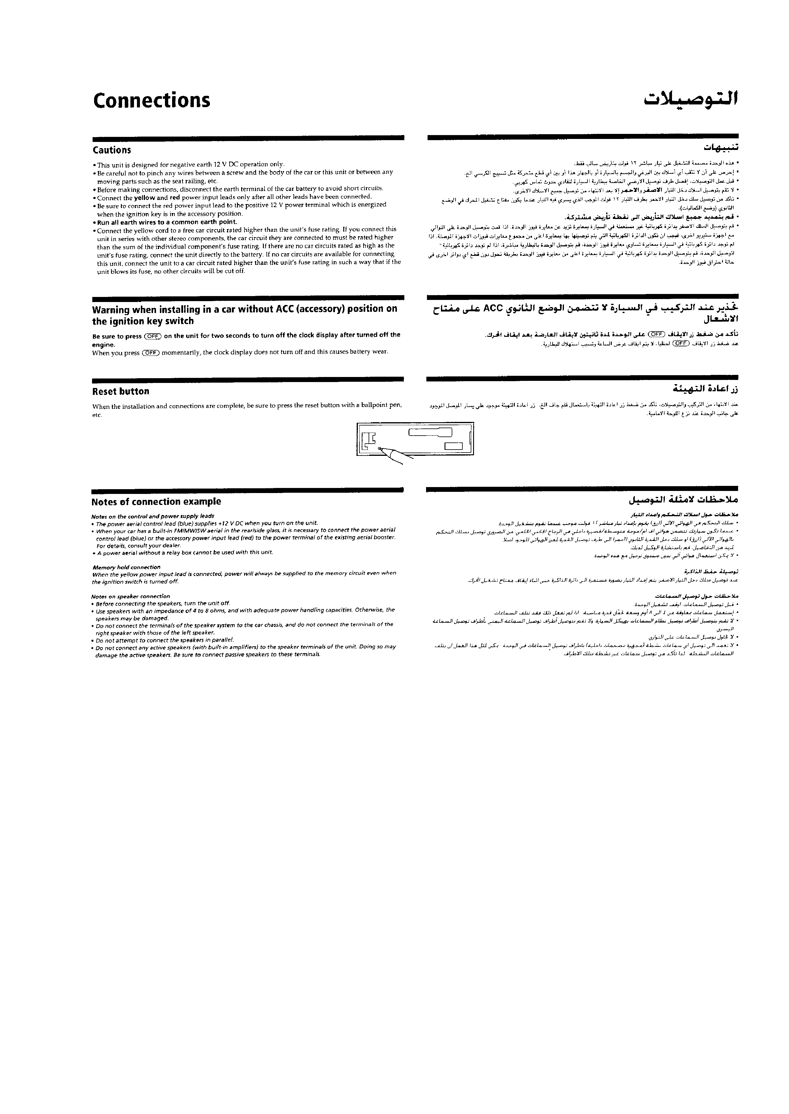
Connections .....................................................................
5
2.
DISASSEMBLY ......................................................... 7
3.
MECHANICAL ADJUSTMENTS ....................... 10
4.
ELECTRICAL ADJUSTMENTS
Test Mode ........................................................................ 10
Tape Deck Section .......................................................... 10
Tuner Section .................................................................. 12
5.
DIAGRAMS
5-1. Note for Printed Wiring Boards and
Schematic Diagrams ....................................................... 14
5-2. Printed Wiring Board MAIN Board ......................... 15
5-3. Schematic Diagram MAIN Board (1/2) ................... 16
5-4. Schematic Diagram MAIN Board (2/2) ................... 17
5-5. Printed Wiring Board KEY Board ........................... 18
5-6. Schematic Diagram KEY Board ............................... 19
5-7. IC Pin Function Description ........................................... 21
6.
EXPLODED VIEWS ................................................ 23
7.
ELECTRICAL PARTS LIST ............................... 26
3
SECTION 1
GENERAL
This section is extracted from
instruction manual.
5
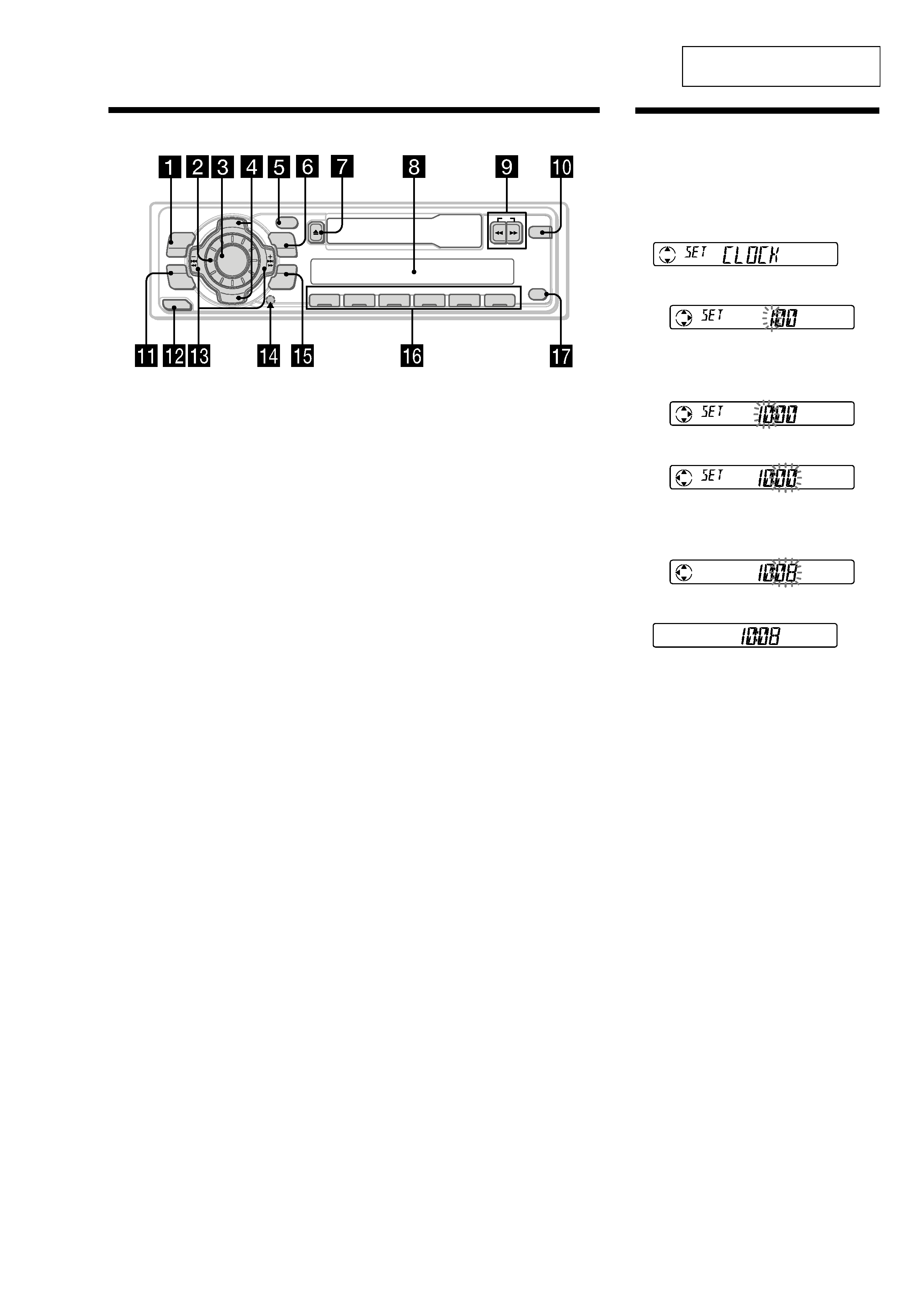
Location of controls
Refer to the pages listed for details.
1 MENU button 7, 8, 9, 10, 12
2 Volume control dial
3 SOURCE (TUNER/CD/MD) button 8, 9, 11
4 PRST/DISC +/ (cursor up/down) buttons
7, 8, 9, 10, 12
During radio reception:
Preset stations select 9
During CD/MD playback:
Disc change 12
5 DSPL (display mode change) button
8, 11, 12
6 MODE button
During radio reception:
BAND select 8, 9
During CD or MD playback:
CD/MD unit select 11
7 Z (eject) button 7
8 Display window
9 m/M (fast winding)/DIR (tape
transport direction change) buttons 7
q; D-BASS button 11
XR-C2604J
D I SC +
PR
S
T+
-
D IS C
PR
ST- -
MODE
DSPL
OFF
DIR
D-BASS
ENTER
MENU
SOUND
RELEASE
1
2
3
4
56
-SEEK/AMS
REP
SHUF
SOURCE
qa SOUND button 10
qs RELEASE (front panel release) button
6, 14
qd SEEK/AMS /+ (cursor left/right) buttons
7, 8, 9, 10, 12
seek 9
Automatic Music Sensor 12
manual search 12
qf Reset button (located on the front side
of the unit behind the front panel) 6
qg ENTER button 7, 8, 9, 10, 12
qh Number buttons
During radio reception
Preset number select 9
During tape/CD/MD playback:
(1) REP 13
(2) SHUF 13
qj OFF button* 6
* Warning when installing in a car
without ACC (accessory) position on
the ignition key switch
Be sure to press (OFF) on the unit for two
seconds to turn off the clock display after
turning off the engine.
When you press (OFF) momentarily, the
clock display does not turn off and this
causes battery wear.
Setting the clock
The clock uses a 12-hour digital indication.
Example: To set the clock to 10:08
1 Press (MENU), then press either side of
(PRST/DISC) repeatedly until "CLOCK"
appears.
1
Press (ENTER).
The hour indication flashes.
2
Press either side of (PRST/DISC) to set
the hour.
3
Press + side of (SEEK/AMS).
The minute indication flashes.
4
Press either side of (PRST/DISC) to set
the minute.
2 Press (ENTER).
The clock starts.
After the clock setting is complete, the
display returns to normal playback mode.
4
5