MICROFILM
SERVICE MANUAL
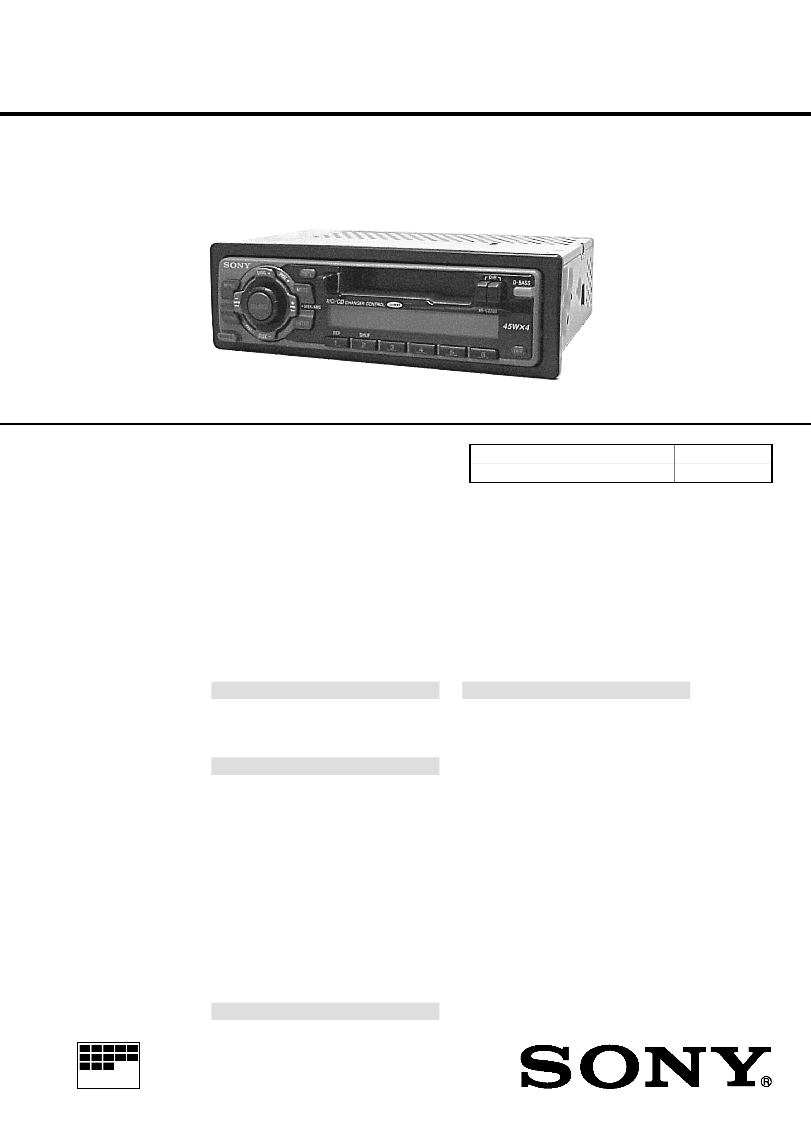
FM/AM CASSETTE CAR STEREO
US Model
Canadian Model
SPECIFICATIONS
XR-C2200/C2300X
Model Name Using Similar Mechanism
NEW
Tape Transport Mechanism Type
MG-36SZ10-32
Photo: XR-C2200
AUDIO POWER SPECIFICATIONS (US model)
POWER OUTPUT AND TOTAL HARMONIC DISTORTION
19 watts (for XR-C2300X)/18 watts (for XR-C2200) per channel
minimum continuous average power into 4 ohms, 4 channels
driven from 20 Hz to 20 kHz with no more than 1 % total
harmonic distortion.
Other specifications
Cassette player section
Tape track
4-track 2-channel stereo
Wow and flutter
0.13 % (WRMS)
Frequency response
30 15,000 Hz
Signal-to-noise ratio
55 dB
Tuner section
FM
Tuning range
87.5 107.9 MHz
Antenna terminal
External antenna connector
Intermediate frequency
10.7 MHz
Usable sensitivity
9 dBf
Selectivity
75 dB at 400 kHz
Signal-to-noise ratio
65 dB (stereo),
68 dB (mono)
Harmonic distortion at 1 kHz
0.7 % (stereo),
0.4 % (mono)
Separation
35 dB at 1 kHz
Frequency response
30 15,000 Hz
AM
Tuning range
530 1,710 kHz
Antenna terminal
External antenna connector
Intermediate frequency
10.7 MHz/450 kHz
Sensitivity
30
µV
Power amplifier section
Outputs
Speaker outputs
(sure seal connectors)
Speaker impedance
4 8 ohms
Maximum power output XR-C2300X:
50 W
× 4 (at 4 ohms)
XR-C2200:
45 W
× 4 (at 4 ohms)
General
Outputs
Audio output
Power antenna relay
control lead
Power amplifier control
lead
Tone controls
Bass
±8 dB at 100 Hz
Treble
±8 dB at 10 kHz
Power requirements
12 V DC car battery
(negative ground)
Dimensions
Approx. 188
× 58 × 182 mm
(7 1/2
× 2 3/8 × 7 1/4 in.)
(w/h/d)
Mounting dimensions
Approx. 182
× 53 × 163 mm
(7 1/4
× 2 1/8 × 6 1/2 in.)
(w/h/d)
Mass
Approx. 1.2 kg (2 lb 10 oz)
Supplied accessories
Parts for installation and
connections (1 set)
Front panel case (1)
Design and specifications are subject to change
without notice.

2
TABLE OF CONTENTS
1.
GENERAL
Location of Controls .......................................................
3
Setting the Clock .............................................................
3
Installation .......................................................................
4
Connections .....................................................................
5
2.
DISASSEMBLY ......................................................... 7
3.
MECHANICAL ADJUSTMENTS ....................... 10
4.
ELECTRICAL ADJUSTMENTS
Test Mode ........................................................................ 10
Tape Deck Section .......................................................... 10
Tuner Section .................................................................. 12
5.
DIAGRAMS
5-1. Note for Printed Wiring Boards and
Schematic Diagrams ....................................................... 14
5-2. Printed Wiring Board MAIN Board ......................... 15
5-3. Schematic Diagram MAIN Board (1/2) ................... 16
5-4. Schematic Diagram MAIN Board (2/2) ................... 17
5-5. Printed Wiring Board KEY Board ........................... 18
5-6. Schematic Diagram KEY Board .............................. 19
5-7. IC Pin Function Description ........................................... 21
6.
EXPLODED VIEWS ................................................ 23
7.
ELECTRICAL PARTS LIST ............................... 26
Flexible Circuit Board Repairing
· Keep the temperature of the soldering iron around 270 °C dur-
ing repairing.
· Do not touch the soldering iron on the same conductor of the
circuit board (within 3 times).
· Be careful not to apply force on the conductor when soldering
or unsoldering.
Notes on chip component replacement
· Never reuse a disconnected chip component.
· Notice that the minus side of a tantalum capacitor may be dam-
aged by heat.
3
SECTION 1
GENERAL
This section is extracted from
instruction manual.
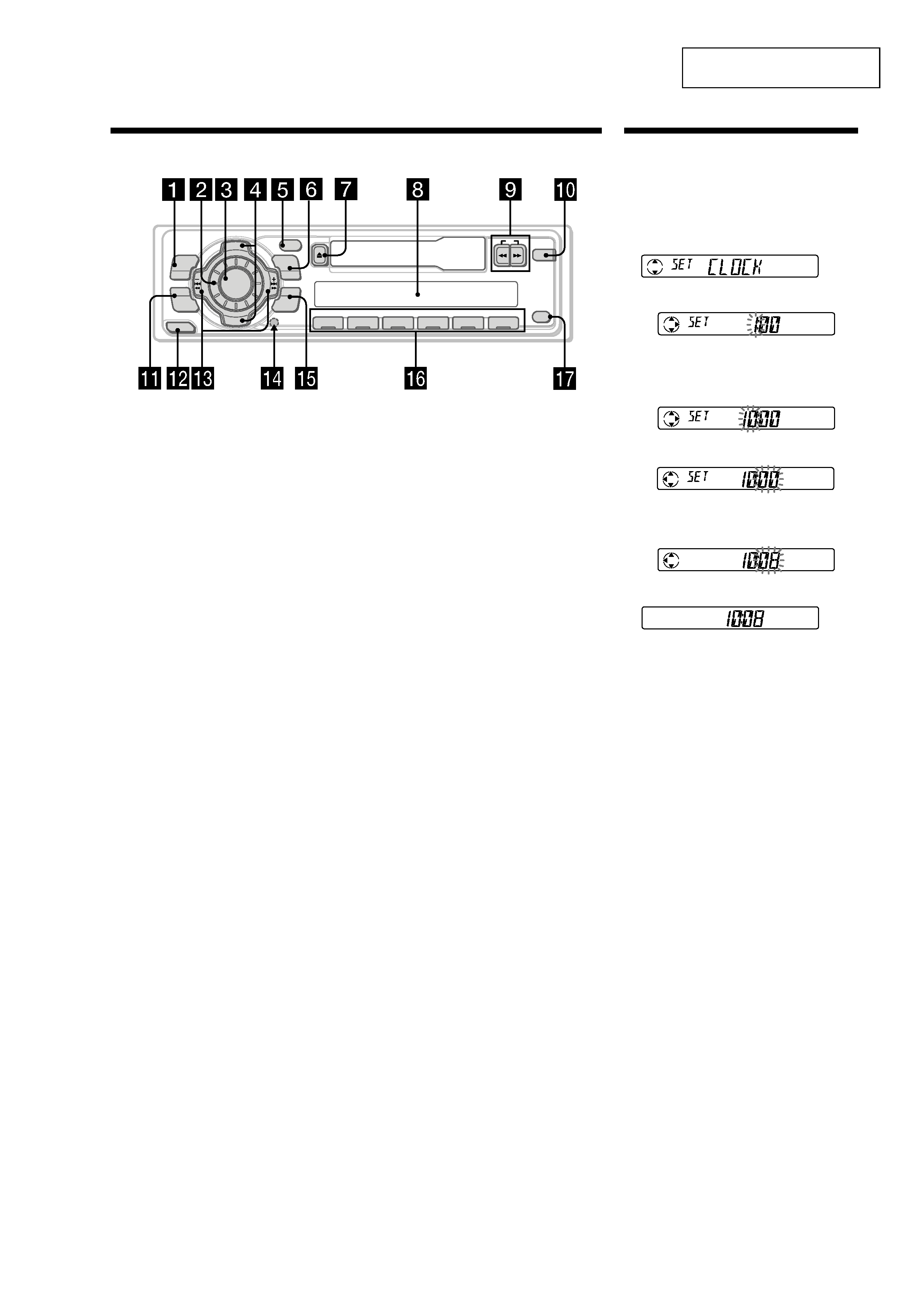
Location of controls
Refer to the pages listed for details.
1 MENU button 7, 9, 10, 11, 13
2 Volume control dial
3 SOURCE (TUNER/CD/MD) button
9, 10, 12
4 PRST/DISC +/ (cursor up/down) buttons
7, 9, 10, 11, 13
During radio reception:
Preset stations select 10
During CD/MD playback:
Disc change 13
5 DSPL (display mode change) button
8, 12, 13
6 MODE button
During radio reception:
BAND select 9, 10
During CD or MD playback:
CD/MD unit select 12
7 Z (eject) button 8
8 Display window
9 m/M(fast winding)/DIR (tape
transport direction change) buttons 8
0 D-BASS button 12
XR-C2200/XR-C2300X
D I SC +
PR
S
T+
-
D IS C
PR
ST- -
MODE
DSPL
OFF
DIR
D-BASS
ENTER
MENU
SOUND
RELEASE
1
2
3
4
56
-SEEK/AMS
REP
SHUF
SOURCE
qa SOUND button 11
qs RELEASE (front panel release) button
6, 15
qd SEEK/AMS /+ (cursor left/right) buttons
7, 9, 10, 11, 13
seek 10
Automatic Music Sensor 13
manual search 13
qf Reset button (located on the front side
of the unit behind the front panel) 6
qg ENTER button 7, 9, 10, 11, 13
qh Number buttons
During radio reception
Preset number select 10
During CD/MD playback:
(1) REP 14
(2) SHUF 14
qj OFF button* 6
* Warning when installing in a car
without ACC (accessory) position on
the ignition key switch
Be sure to press (OFF) on the unit for two
seconds to turn off the clock display after
turning off the engine.
When you press (OFF) momentarily, the
clock display does not turn off and this
causes battery wear.
Setting the clock
The clock uses a 12-hour digital indication.
Example: To set the clock to 10:08
1 Press (MENU), then press either side of
(PRST/DISC) repeatedly until "CLOCK"
appears.
1
Press (ENTER).
The hour indication flashes.
2
Press either side of (PRST/DISC) to set
the hour.
3
Press + side of (SEEK/AMS).
The minute indication flashes.
4
Press either side of (PRST/DISC) to set
the minute.
2 Press (ENTER).
The clock starts.
After the clock setting is complete, the
display returns to normal playback mode.
4
182
mm
53 m
m
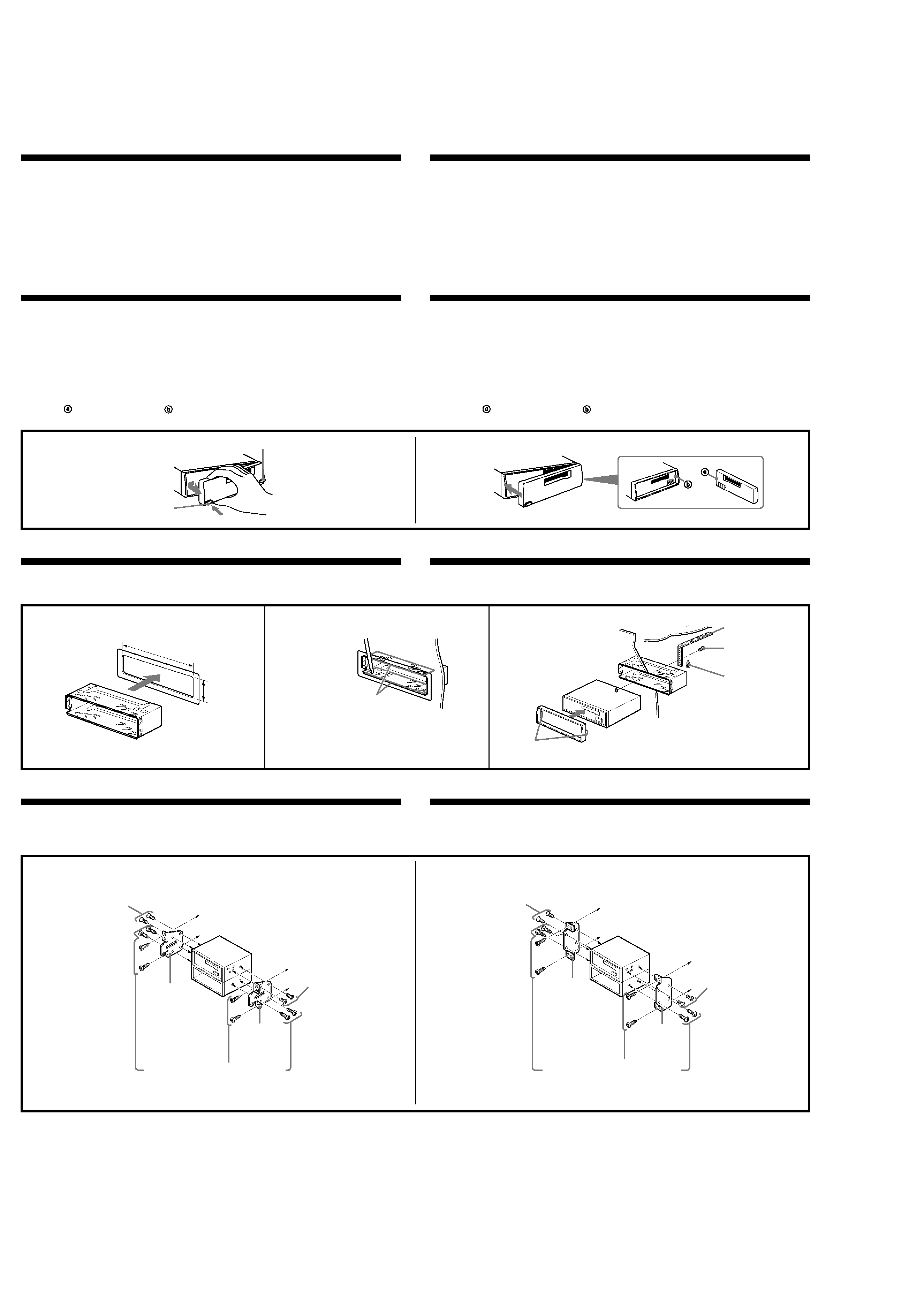
Installation
Precautions
·Choose the installation location carefully so that the unit will not interfere with normal driving.
·Avoid installing the unit in areas subject to dust, dirt, excessive vibration, or high temperatures, such as
in direct sunlight or near heater ducts.
·Use only the supplied mounting hardware for a safe and secure installation.
Mounting angle adjustment
Adjust the mounting angle to less than 20
°.
Note
To prevent malfunction, install only with the supplied screws 5.
A
B
Mounting example
Installation in the dashboard
1
2
3
Bend these claws outward for a
tight fit, if necessary.
Plier ces griffes pour assurer
une prise correcte si nécessaire.
1
Mounting the unit in a Japanese car
You may not be able to install this unit in some makes of Japanese cars. In such a case, consult your Sony
dealer.
How to detach and attach the front panel
Before installing the unit, detach the front panel.
A To detach
Before detaching the front panel, be sure to press (OFF). Press (RELEASE), then slide the front panel a
little to the left, and pull it off towards you.
B To attach
Attach part
of the front panel to part
of the unit as illustrated and push the left side into position
until it clicks.
Installation
Précautions
·Choisir soigneusement l'emplacement d'installation pour que l'appareil ne gêne pas le chauffeur
pendant la conduite.
·Eviter d'installer l'appareil dans un endroit exposé à des températures élevées, comme en plein soleil ou
à proximité d'une bouche d'air chaud, ou à de la poussière, saleté ou vibrations violentes.
·Pour garantir un montage sûr, n'utiliser que le matériel fourni.
Réglage de l'angle de montage
Ajuster l'inclinaison à un angle inférieur à 20
°.
Remarque
Pour éviter tout dysfonctionnement, utilisez uniquement les vis 5 pour le montage.
Exemple de montage
Installation dans le tableau de bord
Installation de l'appareil dans une voiture japonaise
Cet appareil ne peut pas être installé dans certaines voitures japonaise. Consultez, dans ce cas, votre
concessionnaire Sony.
Retrait et pose de la façade
Avant d'installer l'appareil, déposer la façade.
A Pour retirer
Avant de déposer la façade, ne pas oublier d'appuyer sur (OFF). Appuyer ensuite sur (RELEASE), puis
faire glisser la façade légèrement vers la gauche et enlever la façade en tirant à soi.
B Pour attacher
Fixez la partie
de la façade sur la partie
de l'appareil, comme indiqué sur l'illustration, puis poussez
jusqu'au déclic.
(RELEASE)
2
3
Fire wall
Paroi ignifuge
Dashboard
Tableau de bord
1
4
First attach 6 to the unit, then insert
the unit into 1.
Fixez d'abord 6 sur l'appareil et
introduisez ensuite l'appareil dans 1.
6
5
max. size
5
× 8 mm
Dimension
max. 5
× 8 mm
5
max. size
5
× 8 mm
Dimension
max. 5
× 8 mm
Bracket
Support
to dashboard/center console
au tableau de bord/console centrale
Existing parts supplied with your car
Pièces existantes fournies avec la voiture
5
max. size
5
× 8 mm
Dimension
max. 5
× 8 mm
to dashboard/center console
au tableau de bord/console centrale
5
max. size
5
× 8 mm
Dimension
max. 5
× 8 mm
Bracket
Support
Existing parts supplied with your car
Pièces existantes fournies avec la voiture
Bracket
Support
Bracket
Support
TOYOTA
NISSAN
(OFF)
With the UP marking up
Avec l'inscription UP vers le haut
5
Connections
Caution
·This unit is designed for negative ground 12 V DC operation only.
·Be careful not to pinch any wires between a screw and the body of the car or this unit or between any
moving parts such as the seat railing, etc.
·Before making connections, disconnect the ground terminal of the car battery to avoid short circuits.
·Connect the yellow and red power input leads only after all other leads have been connected.
·Be sure to connect the red power input lead to the positive 12 V power terminal which is energized
when the ignition key is in the accessory position.
·Run all ground wires to a common ground point.
·Connect the yellow cord to a free car circuit rated higher than the unit's fuse rating. If you connect this
unit in series with other stereo components, the car circuit they are connected to must be rated higher
than the sum of the individual component's fuse rating. If there are no car circuits rated as high as the
unit's fuse rating, connect the unit directly to the battery. If no car circuits are available for connecting
this unit, connect the unit to a car circuit rated higher than the unit's fuse rating in such a way that if the
unit blows its fuse, no other circuits will be cut off.
Warning when installing in a car without ACC (accessory) position on
the ignition key switch
Be sure to press (OFF) on the unit for two seconds to turn off the clock display after turned off the
engine.
When you press (OFF) momentarily, the clock display does not turn off and this causes battery wear.
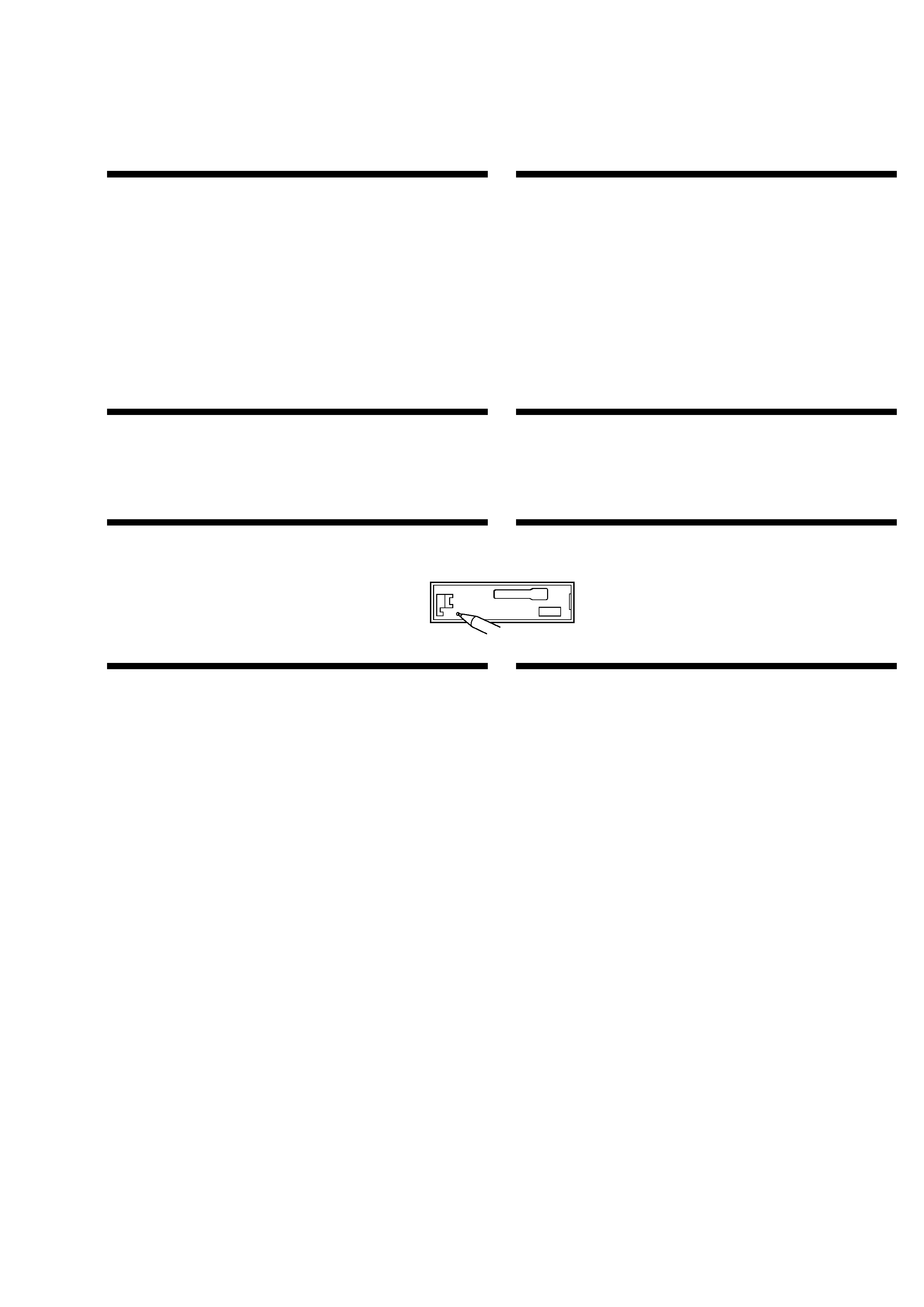
Reset button
When the installation and connections are complete, be sure to press the reset button with a ball-point
pen, etc.
Connexions
Précautions
·Cet appareil est exclusivement conçu pour fonctionner sur une tension de 12 V CC avec masse négative.
·Veiller à ne pas coincer de fils entre une vis et la carrosserie de la voiture ou cet appareil ou encore entre
des pièces mobiles comme les glissières des sièges, etc.
·Avant d'effectuer les connexions, débrancher la borne de terre de la batterie du véhicule pour éviter tout
court-circuit.
·Brancher les fils d'entrée d'alimentation jaune et rouge seulement après avoir terminé tous les autres
branchements.
·Veiller à ne pas raccorder le fil rouge d'entrée d'alimentation à la borne positive de 12 V qui est
alimentée quand la clé de contact est sur la position accessoires.
·Rassembler tous les fils de terre en un point de masse commun.
·Brancher le câble jaune à un circuit libre de la voiture dont la capacité nominale est supérieure à la
capacité du fusible de l'appareil. Si vous branchez cet appareil en série avec d'autres composants stéréo,
le circuit de la voiture auquel ils sont raccordés doit afficher une capacité nominale supérieure à la
somme des capacités individuelles de chaque composant. S'il n'y a pas de circuits de voiture affichant
une capacité égale à la capacité du fusible de l'appareil, brancher l'appareil directement à la batterie. Si
aucun circuit de voiture n'est disponible pour connecter cet appareil, brancher l'appareil à un circuit de
voiture supérieur à la capacité du fusible de l'appareil de telle sorte que si l'appareil grille son fusible,
aucun autre circuit ne soit coupé.
Avertissement en cas d'installation dans une voiture dont le contact
ne comporte pas de position ACC (accessoires)
N'oubliez pas d'appuyer sur le bouton (OFF) de l'appareil pendant deux secondes après avoir
coupé le moteur de façon à désactiver l'affichage de l'horloge.
Si vous appuyez brièvement sur (OFF), l'affichage de l'horloge n'est pas désactivé, ce qui provoque une
usure de la batterie.
Touche de réinitialisation
Quand l'installation et les connexions sont terminées, appuyer sur la touche de réinitialisation avec un
stylo à bille, etc.
Notes of connection example
Notes on the control and power supply leads
· The power antenna control lead (blue) supplies +12 V DC when you turn on the unit.
· When your car has a built-in FM/AM antenna in the rear/side glass, it is necessary to connect the power antenna
control lead (blue) or the accessory power input lead (red) to the power terminal of the existing antenna booster.
For details, consult your dealer.
· A power antenna without a relay box cannot be used with this unit.
Memory hold connection
When the yellow power input lead is connected, power will always be supplied to the memory circuit even when
the ignition switch is turned off.
Notes on speaker connection
· Before connecting the speakers, turn the unit off.
· Use speakers with an impedance of 4 to 8 ohms, and with adequate power handling capacities. Otherwise, the
speakers may be damaged.
· Do not connect the terminals of the speaker system to the car chassis, and do not connect the terminals of the
right speaker with those of the left speaker.
· Do not attempt to connect the speakers in parallel.
· Do not connect any active speakers (with built-in amplifiers) to the speaker terminals of the unit. Doing so may
damage the active speakers. Be sure to connect passive speakers to these terminals.
Remarques sur l'exemple de connexion
Remarques sur les fils de commande et d'alimentation
· Le fil de commande de l'antenne électrique (bleu) fournit une alimentation de + 12 V CC lorsque vous mettez
l'appareil sous tension.
· Si votre voiture est équipée d'une antenne FM/AM intégrée dans la vitre arrière latérale, vous devez raccorder le
fil de commande d'antenne électrique (bleu) ou le fil d'entrée d'alimentation d'accessoire (rouge) à la borne
d'alimentation de l'amplificateur d'antenne existant. Pour plus de détails, consultez votre revendeur.
· Une antenne électrique sans boitier de relais ne peut pas être utilisée avec cet appareil.
Connexion pour la conservation de la mémoire
Lorsque le fil d'entrée d'alimentation jaune est raccordé, le circuit de la mémoire est alimenté en permanence
même si la clé de contact est sur la position d'arrêt.
Remarques sur la connexion des haut-parleurs
· Avant de raccorder les haut-parleurs, mettre l'appareil hors tension.
· Utiliser des haut-parleurs ayant une impédance de 4 à 8 ohms et une capacité adéquate sous peine de les
endommager.
· Ne pas raccorder pas les bornes du système de haut-parleur au châssis de la voiture, et ne pas connecter les
bornes du haut-parleur droit à celles du haut-parleur gauche.
· Ne pas tenter de raccorder les haut-parleurs en parallèle.
· Ne pas connecter de haut-parleurs actifs (équipés d'un amplificateur intégré) aux bornes de haut-parleur de
l'appareil. Les haut-parleurs actifs risquent sinon d'être endommagés. Veiller par conséquent à raccorder des
haut-parleurs passifs à ces bornes.