TECHNICAL INFORMATION
FOR SERVICE ENGINEERS
XR-5800RDS
SEC

Table of Contents
1. Introduction .................................................................. 1
2. Cassette player section ......................................................... 2
3. Tuner section ................................................................. 4
3.1. AM/FM Tuner . . . . . . . . . . . . . . . . . . . . . . . . . . . . . . . . . . . . . . . . . . . . . . . . . . . . . . . . . . . . . . . . . . . . 4
3.2. FM Noise Canceller . . . . . . . . . . . . . . . . . . . . . . . . . . . . . . . . . . . . . . . . . . . . . . . . . . . . . . . . . . . . . . . . 4
3.3. RDS demodulator . . . . . . . . . . . . . . . . . . . . . . . . . . . . . . . . . . . . . . . . . . . . . . . . . . . . . . . . . . . . . . . . . . 5
4. Amplifier section ............................................................. 10
5. Power Supply section ......................................................... 14
6. System Control .............................................................. 16
--i --
1. Introduction
The SONY XR-5800RDS series are the first car radio-cassette players that include an RDS (Radio
Data System) decoder. The RDS decoder features the primary RDS functions, like Programme
Identification (PI), Programme Service Name (PS), Alternative Frequencies (AF) and Traffic Pro-
gramme / Traffic Announcement (TP/TA). In addition, the clock time is displayed by using the CT
data.
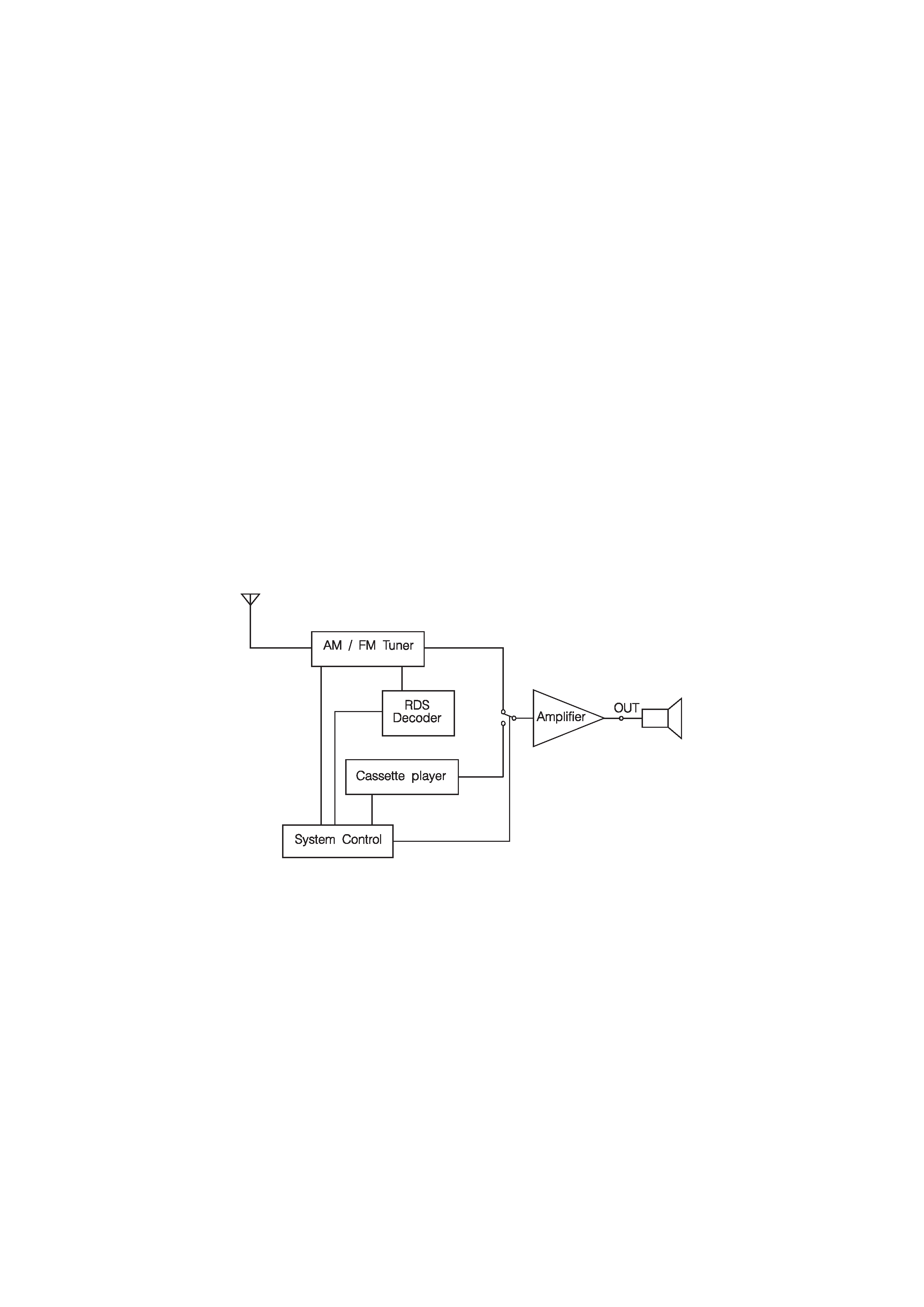
As can be seen from the simplified block diagram in figure 1.1, the set is very straightforward. It
comprises an AM/FM stereo tuner with RDS decoder, an auto reverse cassette player with Dolby B
Noise Reduction and a power amplifier. The differences between the related models are :
· XR-5800RDS: AM tuning range : 531 - 1602 kHz
· XR-5801RDS: AM tuning range : MW: 531 - 1602 kHz
LW: 153 - 281 kHz
· XR-5802RDS: as XR-5800RDS but additionally with ARI decoder (current German trafic
announcement system).
In the following chapters the different blocks are discussed in detail and their circuit operation is
explained.
Fig. 1.1. Block Diagram of XR-5800RDS
--1 --

2. Cassette player section
The cassette player circuit is shown in figure 2.1. According to the position of S902, the music signals
coming from the forward or reverse heads are switched to the pre-amplifier (IC372). S902-3 informs
IC701 (system controller) whether the mechanism is in the forward or reverse mode. IC372 is an
OPAMP with the necessary frequency equalisation in the feedback loop. Q101, Q201 and Q301 switch
the feedback loop between 120
µs (Type I-tape) and 70 µs (type II-tape and IV-tape). The L & R
outputs of IC372 pass RV101 and RV201 respectively before going to the Dolby NR (IC373). RV101
and RV201 adjust the output level to ensure proper Dolby Noise Reduction.
The L & R output signals are added through R106 and R206 to form the input of the AMS IC (IC371).
Q372 switches the AMS feature on or off. When during FF or REW a blank space of about 4 seconds
is detected, plunger PM902 will be activated via Q371 and Q373 to release the FF or REW mode. The
time constant of 4 seconds is determined by C373 and R372.
S901 is switched on when a cassette has been loaded, while S903 is on during FF or REW mode.
These switches provide the syscon with information about the MD. Plunger PM901 and M901 are
connected in parallel and switched on by Q451 and Q452. The plunger pulls a lever that activates a
gear so that the head and pinch rollers are moved towards the tape. When the tape stops running (e.g.
when the power is switched off), the head and pinch rollers will be pushed back by a spring to prevent
them from touching the tape.
--2 --
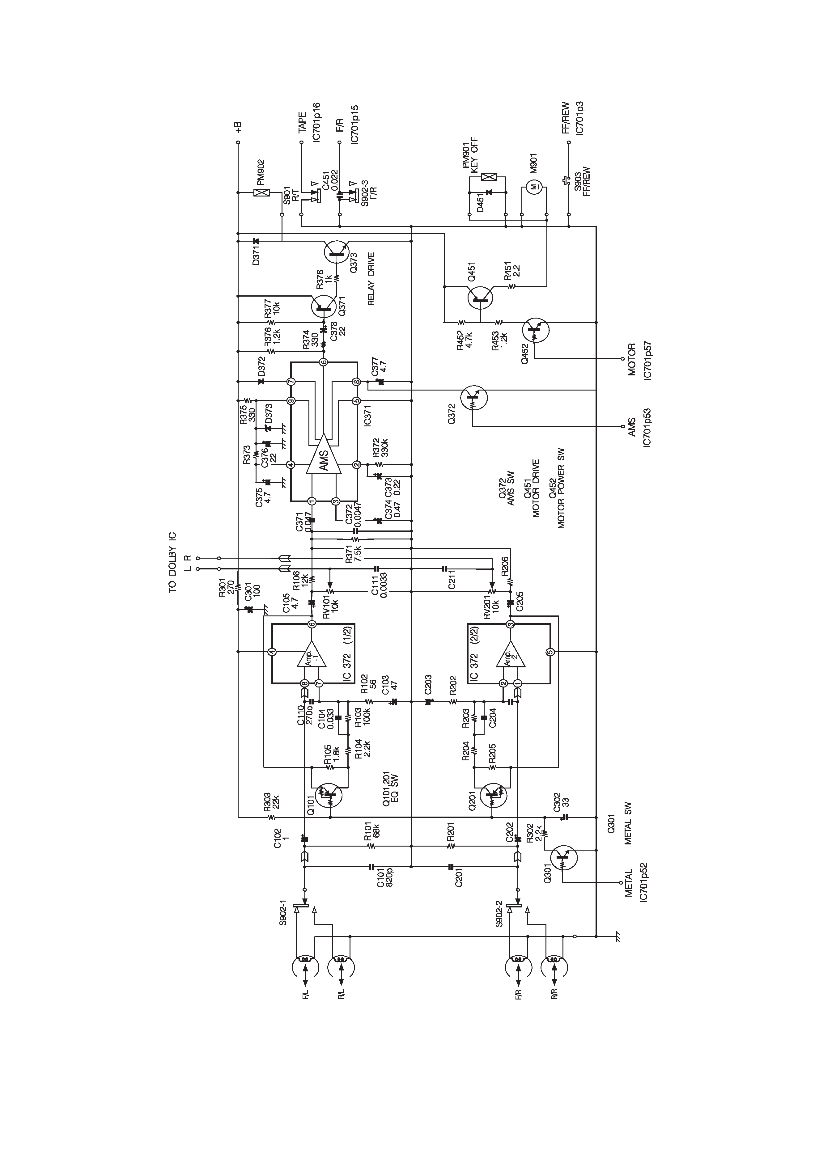
Fig. 2.1. Deck Board
--3 --