MICROFILM
UK Model
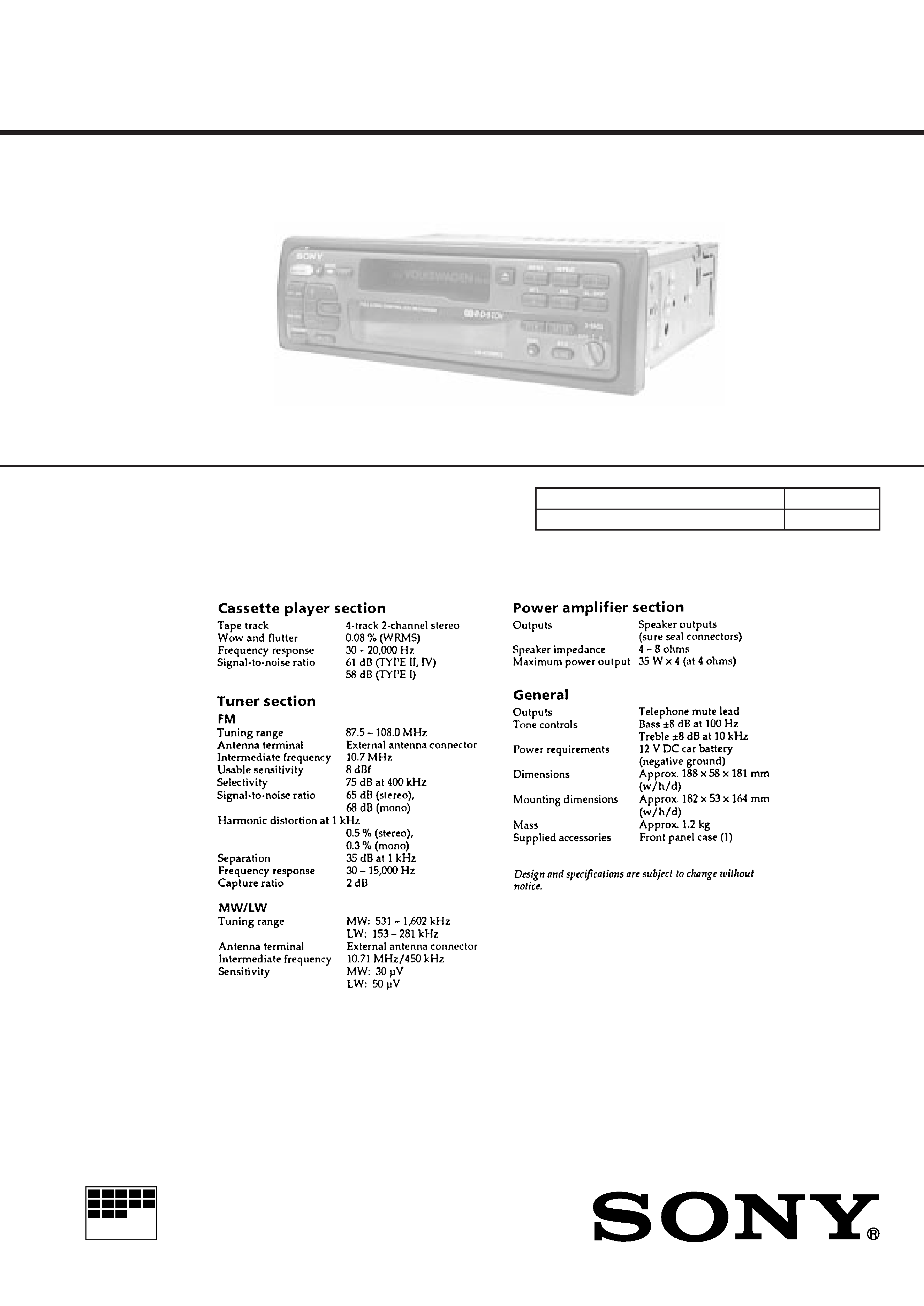
SERVICE MANUAL
FM/MW/LW CASSETTE CAR STEREO
SPECIFICATIONS
Model Name Using Similar Mechanism
XR-3740
Tape Transport Mechanism Type
MG-52A-135
XR-4758RDS/4759RDS
Photo: XR-4759RDS

2
TABLE OF CONTENTS
1.
GENERAL
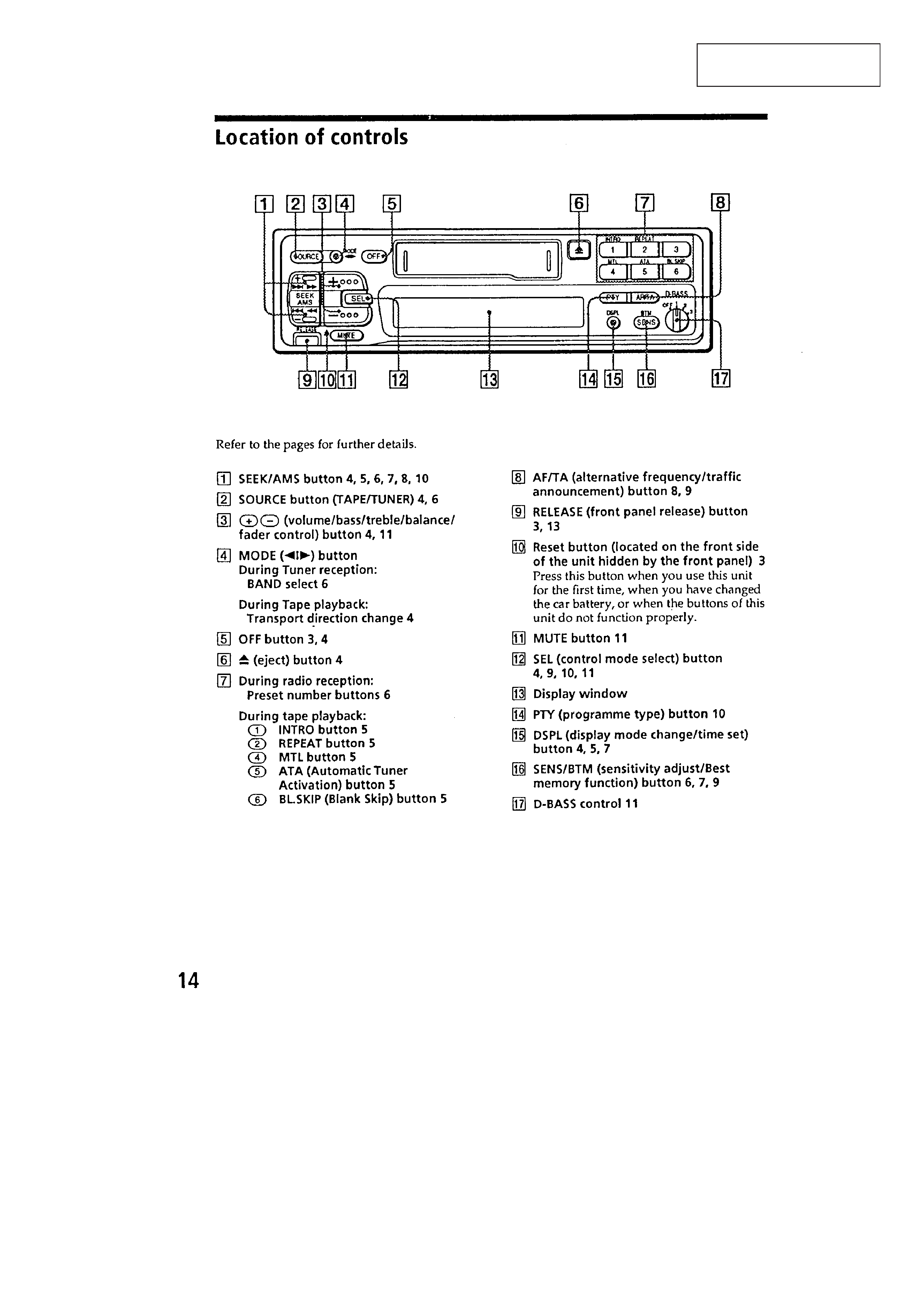
Location of Controls ........................................................ 3
2.
DISASSEMBLY ......................................................... 4
3.
ASSEMBLY OF MECHANISM DECK ........... 6
4.
MECHANICAL ADJUSTMENTS ....................... 12
5.
ELECTRICAL ADJUSTMENTS
Test Mode ........................................................................ 12
Tape Deck Section ........................................................... 13
Tuner Section ................................................................... 13
6.
DIAGRAMS
6-1.
IC Pin Function Description ............................................ 16
6-2.
Printed Wiring Boards MAIN Section ..................... 18
6-3.
Schematic Diagram MAIN Section ........................... 21
6-4.
Printed Wiring Board KEY Section ......................... 27
6-5.
Schematic Diagram KEY Section ............................ 29
7.
EXPLODED VIEWS ................................................ 34
8.
ELECTRICAL PARTS LIST ................................ 38
SERVICING NOTES
Flexible Circuit Board Repairing
· Keep the temperature of the soldering iron around 270 ° C dur-
ing repairing.
· Do not touch the soldering iron on the same conductor of the
circuit board (within 3 times).
· Be careful not to apply force on the conductor when soldering
or unsoldering .
Notes on chip component replacement
· Never reuse a disconnected chip component.
· Notice that the minus side of a tantalum capacitor may be dam-
aged by heat.
3
SECTION 1
GENERAL
This section is extracted
from instruction manual.
4
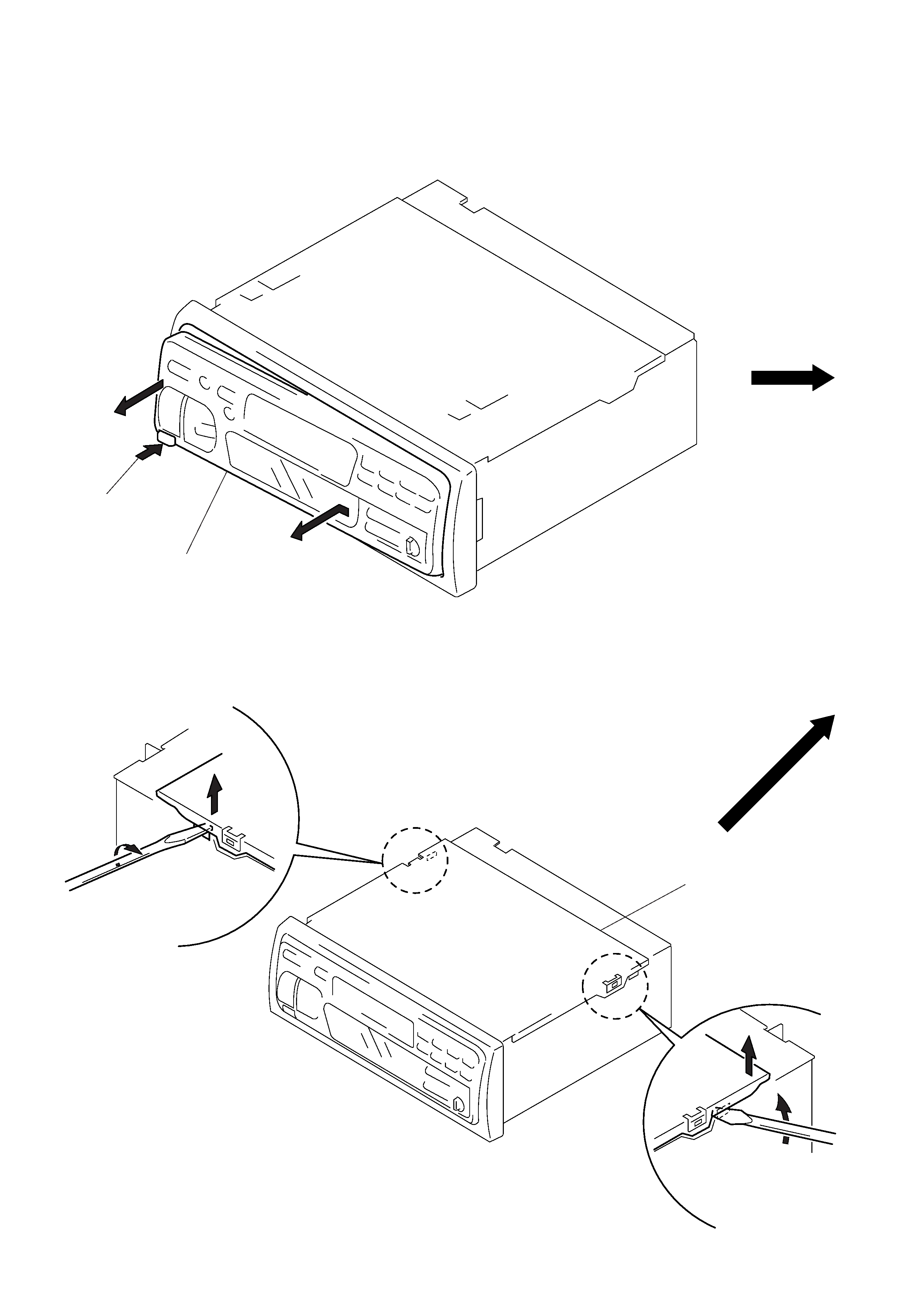
Note: Follow the disassembly procedure in the numerical order given.
FRONT PANEL ASS'Y
SECTION 2
DISASSEMBLY
1 Push the button
(release).
A
2 Remove the front panel ass'y
to the direction of the arrow A.
COVER ASS'Y
2
1
3 cover ass'y
1
2
5
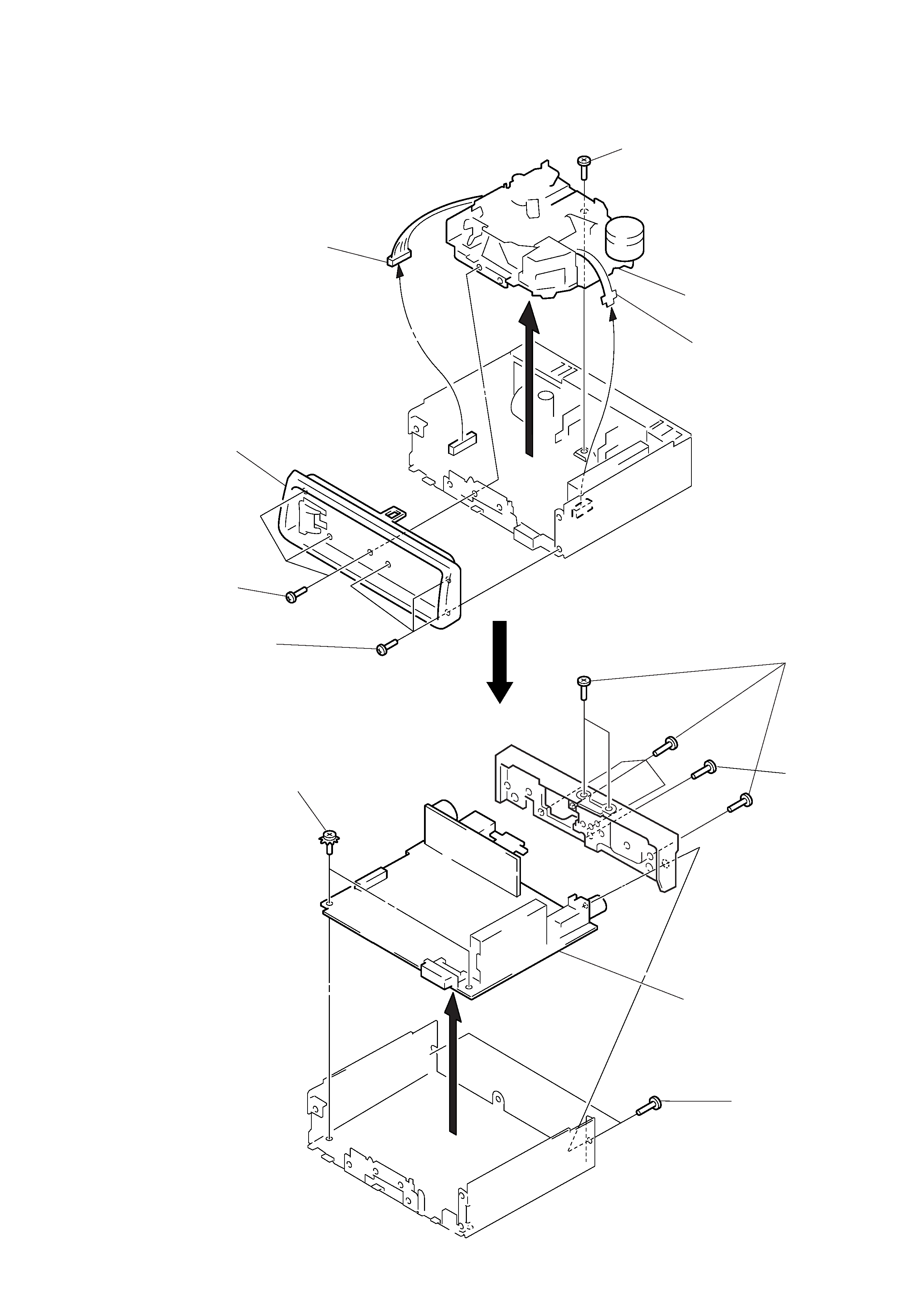
MAIN BOARD, HEAT SINK
1 three screws
(PTT2.6
× 6)
5 screw
(PTT2.6
× 6)
6 mechanism deck
(MG-52A-135)
4 flexible flat cable
(CN351)
1 three screws
(PTT2.6
× 6)
2 sub panel
3 connector
(CN352)
1 screw
(PTT2.6
× 6)
3 main board
1 two screws
(PTT2.6
× 6)
2 two ground point
screws
4 six screws
(PTT2.6
× 8)
SUB PANEL, MECHANISM DECK (MG-52A-135)