SERVICE MANUAL
FM/MW/SW CASSETTE CAR STEREO
Saudi Arabia Model
SPECIFICATIONS
XR-1780
Model Name Using Similar Mechanism
XR-1790
Tape Transport Mechanism Type
MG-36SZ9-32
Cassette player section
Tape track
4-track 2-channel stereo
Wow and flutter
0.13 % (WRMS)
Frequency response
30 15,000 Hz
Signal-to- noise ratio
55 dB
Tuner section
FM
Tuning range
87.5 108.0 MHz
Aerialterminal
External aerial connector
Intermediate frequency
10.7 MHz
Usable sensitivity
9 dBf
Selectivity
75 dB at 400 kHz
Signal-to-noise ratio
65 dB (stereo),
68 dB (mono)
Harmonic distortion at 1 kHz
0.7% (stereo),
0.4% (mono)
Separation
35 dB at 1 kHz
Frequency response
30 15,000 Hz
MW/SW
Tuning range
MW Tuning interval:
531 1,602 kHz
SW tuning interval:
SW1:
2,940 7,735 kHz
SW2:
9,500 18,135 kHz (except
for 10,140 11,575 kHz)
Aerialterminal
External aerial connector
Intermediate frequency
10.71 MHz/450 kHz
Sensitivity
30 µV
Power amplifier section
Outputs
Speaker outputs
(sure seal connectors)
Speaker impedance
4 8 ohms
Maximum power output 35 W
× 4 (at 4 ohms)
General
Output lead
Power aerial relay control
lead
Tone controls
Bass ±8 dB at 100 Hz
Treble ±8 dB at 10 kHz
Power requirements
12 V DC car battery
(negative earth)
Dimensions
Approx. 186
× 57 × 176 mm
(w/h/d) not incl.
projecting parts and
controls
Mounting dimension
Approx. 182
× 53 × 163 mm
(w/h/d) not incl.
projecting parts and
controls
Mass
Approx.1.2 kg
Supplied accessories
Parts for installationand
connections (1 set)
Design and specifications are subject to change
without notice.

2
TABLE OF CONTENTS
1.
GENERAL
Location of Controls .......................................................
3
Setting the Clock .............................................................
3
Installation .......................................................................
4
Connections .....................................................................
5
2.
DISASSEMBLY ......................................................... 7
3.
MECHANICAL ADJUSTMENTS ....................... 11
4.
ELECTRICAL ADJUSTMENTS
Tape Deck Section .......................................................... 11
Tuner Section .................................................................. 12
5.
DIAGRAMS
5-1. Note for Printed Wiring Boards and
Schematic Diagrams ....................................................... 15
5-2. Printed Wiring Board MAIN Board ........................ 17
5-3. Schematic Diagram MAIN Board (1/2) ................... 18
5-4. Schematic Diagram MAIN Board (2/2) ................... 19
5-5. Printed Wiring Board CONTROL Board ................ 20
5-6. Schematic Diagram CONTROL Board ................... 20
5-7. IC Pin Function Description ........................................... 21
6.
EXPLODED VIEWS ................................................ 23
7.
ELECTRICAL PARTS LIST ............................... 29
Flexible Circuit Board Repairing
· Keep the temperature of the soldering iron around 270 °C dur-
ing repairing.
· Do not touch the soldering iron on the same conductor of the
circuit board (within 3 times).
· Be careful not to apply force on the conductor when soldering
or unsoldering.
Notes on chip component replacement
· Never reuse a disconnected chip component.
· Notice that the minus side of a tantalum capacitor may be dam-
aged by heat.
3
SECTION 1
GENERAL
This section is extracted from
instruction manual.
4
GB
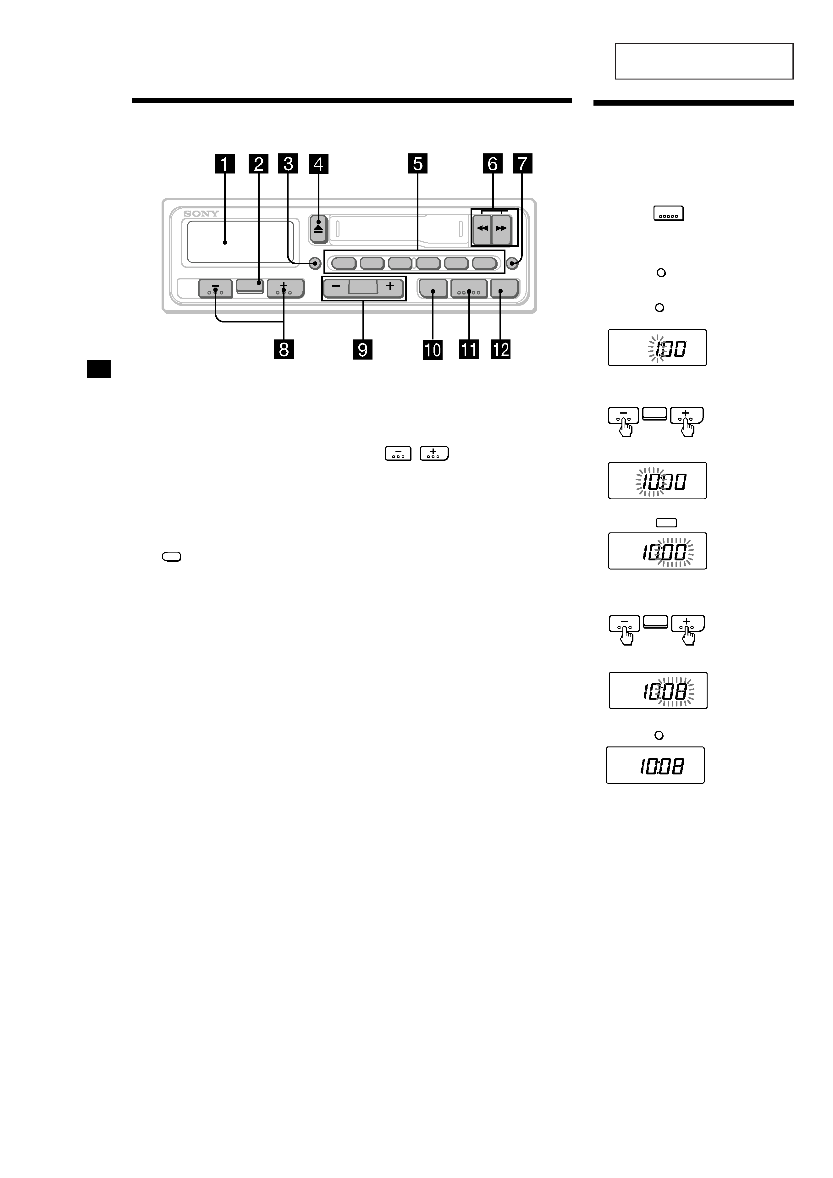
Location of controls
7 LCL (local seek) button 7
8
(volume/bass/treble/
balance/fader control) buttons 5, 8
9 SEEK/MANU button 7
0 LOUD (loudness) button 8
qa TUNER/A MEM (radio on
· band select/
automatic memory) button 5, 7, 8
qs OFF button
Refer to the pages listed for furtherdetails.
1 Display window
2 SEL (control mode select) button 5, 8
3 DSPL (display mode change/time set)
button 5
4 Z (eject) button 6
5 During radio reception:
Preset number buttons 8
During tape playback:
ATA
1
ATA (Automatic Tuner
Activation) button 6
6 m/ M (fast-winding)/DIR (tape
transport direction change) buttons 6
DSPL
ATA
SEEK
MANU
LCL
A MEM
DIR
2
13
6
4
5
XR-1780
SEL
TUNER
OFF
LOUD
The clock activates.
6 Press the DSPL button.
Note
The clock cannot be set unless the power is turned
on. Set the clock after you turn on the radio, or
during tape playback.
Setting the clock
The clock has a 12-hour digitalindication.
Example: To set the clock to 10:08
1 Turn the ignition switchof your car on.
2 Press the
TUNER
button,or insert a
cassette to turnthe unit on.
3 Display the time.
(Press the
DSPL
button during unit
operation.)
4 Press the
DSPL
button for more than two
seconds.
Set the hour.
5 Press the SEL button.
Set the minute.
(to go
backward)
(to go forward)
The hour digits blinks.
The minute digits blink.
(to go
backward)
(to go forward)
4
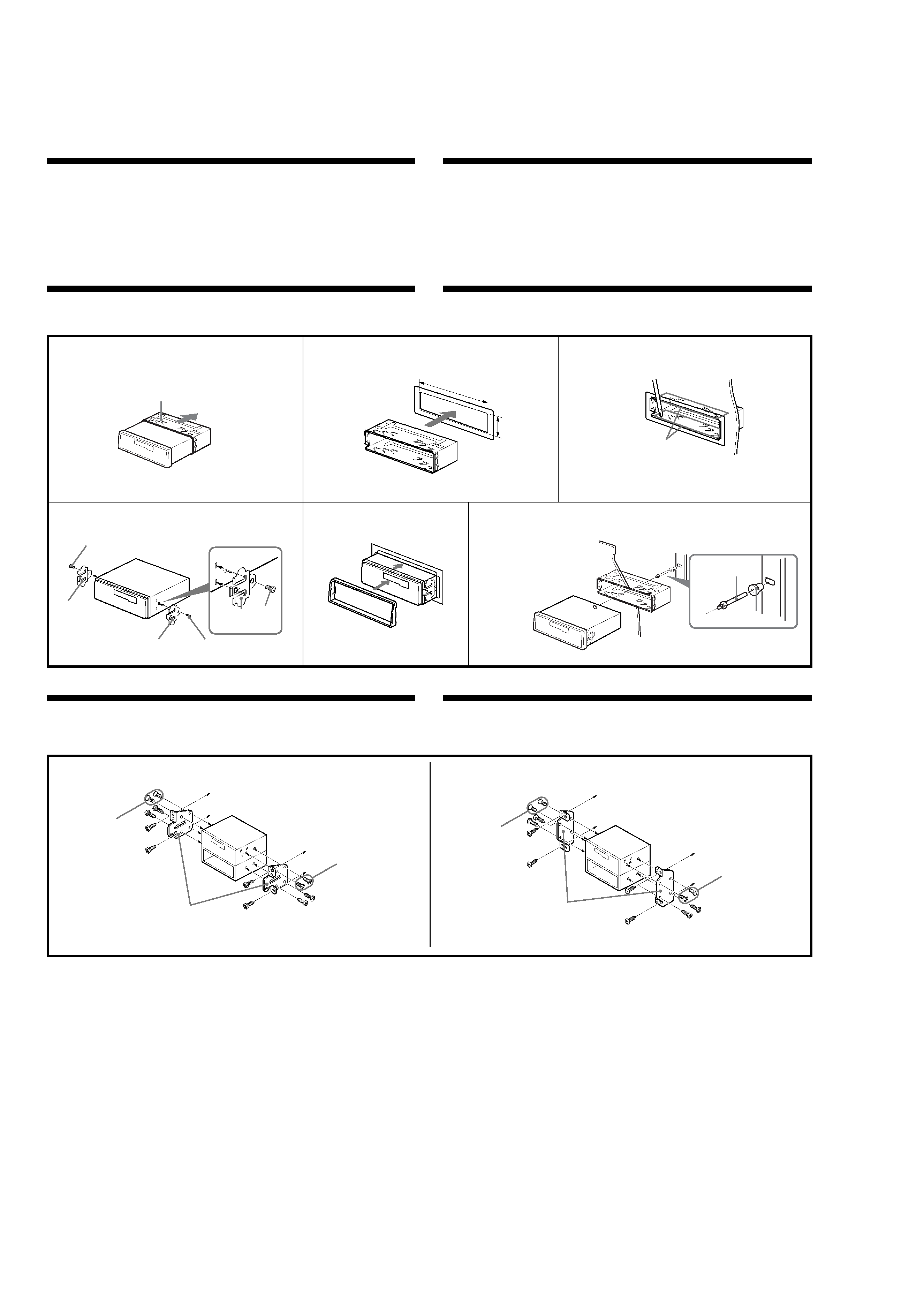
Installation
Precautions
·Choose the installing location carefully so that the unit will not interfere with the normal driving
functions of the driver.
·Avoid installing the unit where it would be subject to high temperatures, such as from direct sunlight or
hot air from the heater, or where it would be subject to dust, dirt or excessive vibration.
·Use only the supplied mounting hardware for a safe and secure installation.
Mounting angle adjustment
Adjust the mounting angle to less than 20°.
Mounting example
Installing in the dashboard
Bend these claws, if necessary.
Ædô« vb« «« XU
VOd
VU<« Ác
s
5
3
1
2
1
Dashboard
«oe«bF« Wu
Fire wall
od(« eU
4
5
6
4
Remove the bracket.
Æ"uI« Ye
To support the unit
"UN'« rb
1
182
mm
53 mm
6
5
5
6
2
3
1
Mounting the unit in a Japanese car
You may not be able to install this unit in some makes of Japanese cars. In such a case, consult your
nearest Sony dealer.
NISSAN
TOYOTA
to dashboard/center console
wDu« uuJ« ,ËbMØ«oe«bF« Wu
v«
to dashboard/center console
wDu« uuJ« ,ËbMØ«oe«bF« Wu
v«
Bracket
VOd
...bU
6
max. size
ø 5
× 8 mm
r
vB«
¿
3 TM µ
Bracket
VOd
...bU
6
max. size
ø 5
× 8 mm
r
vB«
¿
3 TM µ
6
max. size
ø 5
× 8 mm
r
vB«
¿
3 TM µ
6
max. size
ø 5
× 8 mm
r
vB«
¿
3 TM µ
Note
To prevent malfunction, install only with the supplied screws
6.
d«
VO
WOUO
UNOM
·
Æ...--UOKà W¹oeUFë ...oeUOIë nzUþË lÄ ¡UML« UIzUZ ÊuJð ô YO×Ð W¹UMFÐ VOÂd²Ã« lÁuÄ --UO²sUÐ rÁ
·
YOS Ë« ¨W¹Ubë sÄ ssUë ¡«uNKà ˫ dýU³*« fLAë ¡uCà ÷dF²ð ÊQ ¨WFHðdÄ ...--«dS Ul--bà W{dFÄ ÊuJð YOS ...bSuë VOÂdð VM&
Æ...bz«eë «"«e²¼ô« Ë« OEUÝËô« Ë« --U³GKà ÷dF²ð
·
ÆsÄü« VOÂd²Ã«Ë WÄöë ÊULCà pÃË ...eN:« pKð dOz VOÂdð UÄeK²Ä qLF²ð ô
VOd« WË«" j{
sÄ qÁ VOÂd²Ã« W¹Ë«" j³{«
°
Æ
VOd« vK
U
«oe«bF« Wu
vK
VOd«
WOUU
...--UO
w
...bu« VOd
Æp¹bà w½uÝ U-²M* Y"uÄ »dÁ« ...--UA²ÝUÐ rÁ ¨WÃU(« pKð w
Æ «--UOë Y«u½« iFÐ w
UN³OÂdð sJ1 ô ...bSuë Ác¼
WEö
jI
...eN:« w«d« ULFU
...bu« VOd
r
¨qDF« lM*
6
Æ
5
Caution
·This unit is designed for negative earth 12 V DC operation only.
·Be careful not to pinch any wires between a screw and the body of the car or this unit or between any
moving parts such as the seat railing, etc.
·Before making connections, disconnect the earth terminal of the car battery to avoid short circuits.
·Connect the yellow and red power input leads only after all other leads have been connected.
·Be sure to connect the red power input lead to the positive 12 V power terminal which is energized
when the ignition key is in the accessory position.
·Run all earth wires to a common earth point.
·Be sure to insulate any loose unconnected wires with electrical tape for safety.
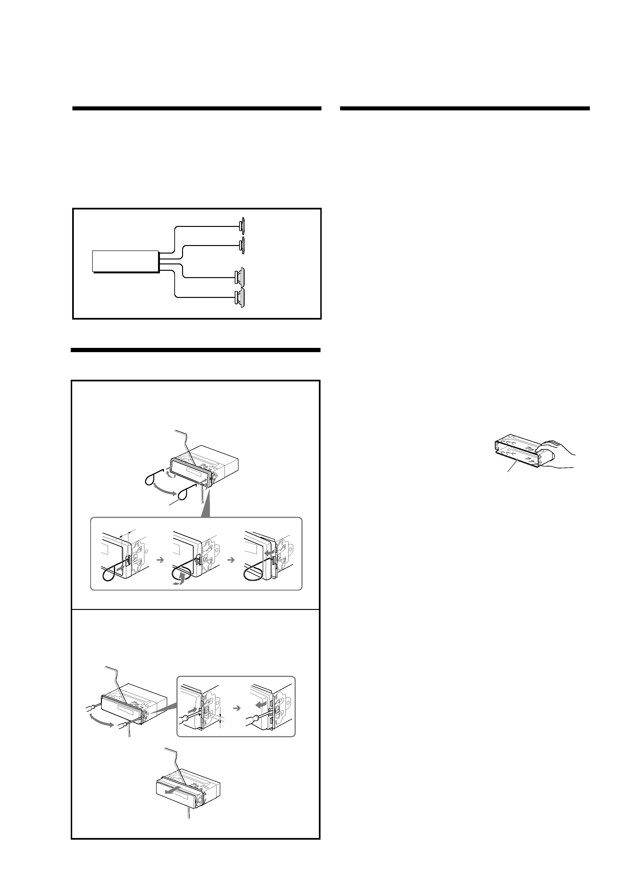
Connections
Connection diagram
XR-1780
Front speakers
WOUô«
UUL«
Rear speakers
WOHK)«
UUL«
UNOM
·
ÆjI
VÃUÝ i¹--Q²Ð XÃu
± dýU³Ä --UOð vKZ qOGA²Kà WLLBÄ ...bSuë Ác¼
·
Æaë wÝdJë ZOOð q¦Ä WÂd×²Ä lDÁ Í 5Ð Ë «c¼ "UN'UÐ Ë ...--UOÃUÐ r'«Ë wzd³Ã« 5Ð ,,öÝ Í VI¦ð ô Ê vKZ 'dS
·
ÆwÐdN "U9 ÀËbS ÍoeUH²Ã ...--UOë W¹--UD³Ð WU)« w{--ô« qOuð ·dÞ qB ¨ öOu²Ã« qLZ q³Á
·
--UO²Ã« qsoe ,,öÝ« qOu²Ð rIð ô
dHô«
Ë
dLô«
ÆÈdsô« ,,öÝô« lOLl qOuð sÄ ¡UN²½ô« bFÐ ô
·
l{uë w
,,d;« qOGAð ÕU²HÄ ÊuJ¹ UÄbMZ --UO²Ã« tO
Íd¹ Ícë Vlu*« XÃu
± --UO²Ã« ·dDÐ dLSô« --UO²Ã« qsoe pKÝ qOuð sÄ bÂQð
Æ© UOÃULJë l{Ë® Íu½U¦Ã«
·
ÆWdA
i--Q
WDI
v« i--Q« ,,ö« lOL
bbL
r
·
ÆÊUÄúà wzUÐdN j¹dý ULF²ÝUÐ WKuÄ dOz ,,öÝöà ¡Uð--« Í eZ sÄ bÂQð
qOu«
qOu« jD
Dismounting the unit
"UN'« pOJH
1 Insertthesuppliedtool
8 between the unit and the frame, and rotate 90º to release the
hidden mounting spring. Repeat on the opposite side and remove the frame.
WId*« ...«oe_« UsoeSÐ rÁ
8
V½U'« vKZ --«dJ²ÃUÐ rÁ ÆwH<« VOÂd²Ã« wzd³Ã« d¹dײà Wl--oe Ád¹Ëb²Ð rÁË ¨--UÞù«Ë "UN'« 5Ð
Æ--UÞù« Ye½«Ë fÂUF*«
10mm
3 ±
90¡
W--oe
2 Insertaflatheadscrewdriverbetweenthebracketandmountingspring.Gentlyprythe
spring toward the unit while pulling the unit out a little. Repeat on the opposite side and
remove the unit.
ÆÃ--UKà V×Ý ¡UML pÃË nDKÐ "UN'« ÁU&UÐ wzd³Ã« ldÐ rÁ ÆVOÂd²Ã« wzdÐË "uIë 5Ð "dë `DÄ wz«dÐ pHÄ UsoeSÐ rÁ
Æ"UN'« Ye½«Ë fÂUF*« V½U'« vKZ --«dJ²Ð rÁ
8
4mm
3¥
Caution
Cautionary notice for handling the bracket
1.
Handle the bracket carefully to avoid injuring your fingers.
tOM
VOÂd²Ã« ...bZUÁ ËUMð uS W¹d¹c% WESöÄ
1
Æ
ÆpFÐU« Õdl ÍoeUH²Ã 'd×Ð VOÂd²Ã« ...bZUÁ ËUMð
Note
The tool
8 is used for removing the unit.
Be sure to keep it for future use.
WEö
...«oe_« Âb²ð
8
Æ"UN'« YeMÃ
ö³I²Ä UNÄ«b²Ýù UNÐ ÿUH²Sù« sÄ bÂQð
Î
Æ
1