XR-1750
US Model
E Model
Australian Model
SERVICE MANUAL
FM/AM CASSETTE CAR STEREO
SPECIFICATIONS
Model Name Using Similar Mechanism
NEW
Tape Transport Mechanism Type
MG-52A-135
AUDIO POWER SPECIFICATIONS (US model)
POWER OUTPUT AND TOTAL HARMONIC DISTORTION
13 watts per channel minimum continuous average power into 4 ohms, 4 channels driven from
20 Hz to 20 kHz with no more then 1% total harmonic distortion.
Cassette player section
Tape track
4-track 2-channel stereo
Wow and flutter
0.08% (WRMS)
Frequency response
30 20,000 Hz
Signal-to-noise ratio
58 dB
Tuner section
FM
Tuning range
US model:
87.5 107.9 MHz
E, Australian model:
50 kHz/200 kHz switchable
87.5 108.0 MHz (at 50 kHz step)
87.5 107.9 MHz (at 200 kHz step)
Antenna terminal
External antenna connector
Intermediate frequency 10.7 MHz
Usable sensitivity
8 dBf
Selectivity
75 dB at 400 kHz
Signal-to-noise ratio
65 dB (stereo), 68 dB (mono)
Harmonic distortion at 1 kHz
0.5% (stereo), 0.3% (mono)
Separation
35 dB at 1 kHz
Frequency response
30 15,000 Hz
Capture ratio
2 dB
AM
Tuning range
US model:
530 1,710 kHz
E, Australian model:
9 kHz/10 kHz switchable
531 1,602 kHz (at 9 kHz step)
530 1,710 kHz (at 10 kHz step)
Antenna terminal
External antenna connector
Intermediate frequency 10.71 MHz/450 kHz
Sensitivity
30 µV
Power amplifier section
Outputs
Speaker outputs (sure seal connectors)
Speaker impedance
4 8 ohms
Maximum power output 35 W
× 4 (at 4 ohms)
General
Outputs
Power antenna control lead
Power amplifier control lead
Rear line out (1)
Tone controls
Bass ±8 dB at 100 Hz
Treble ±8 dB at 10 kHz
Power requirements
12 V DC car battery (negative ground)
Dimensions
Approx. 188
× 58 × 182 mm
(71/2
× 23/8 × 71/4 in.) (w/h/d)
Mounting dimensions
Approx. 182
× 53 × 161 mm
(71/4
× 21/8 × 63/8 in.) (w/h/d)
Mass
Approx. 1.2 kg (2 lb. 10 oz.)
Supplied accessories
Parts for installation and connections (1 set)
Design and specifications are subject to change without notice.
Ver 1.1 2001.04
9-925-564-12
Sony Corporation
2001D0500-1
e Vehicle Company
C
2001.4
Shinagawa Tec Service Manual Production Group

2
TABLE OF CONTENTS
1.
GENERAL
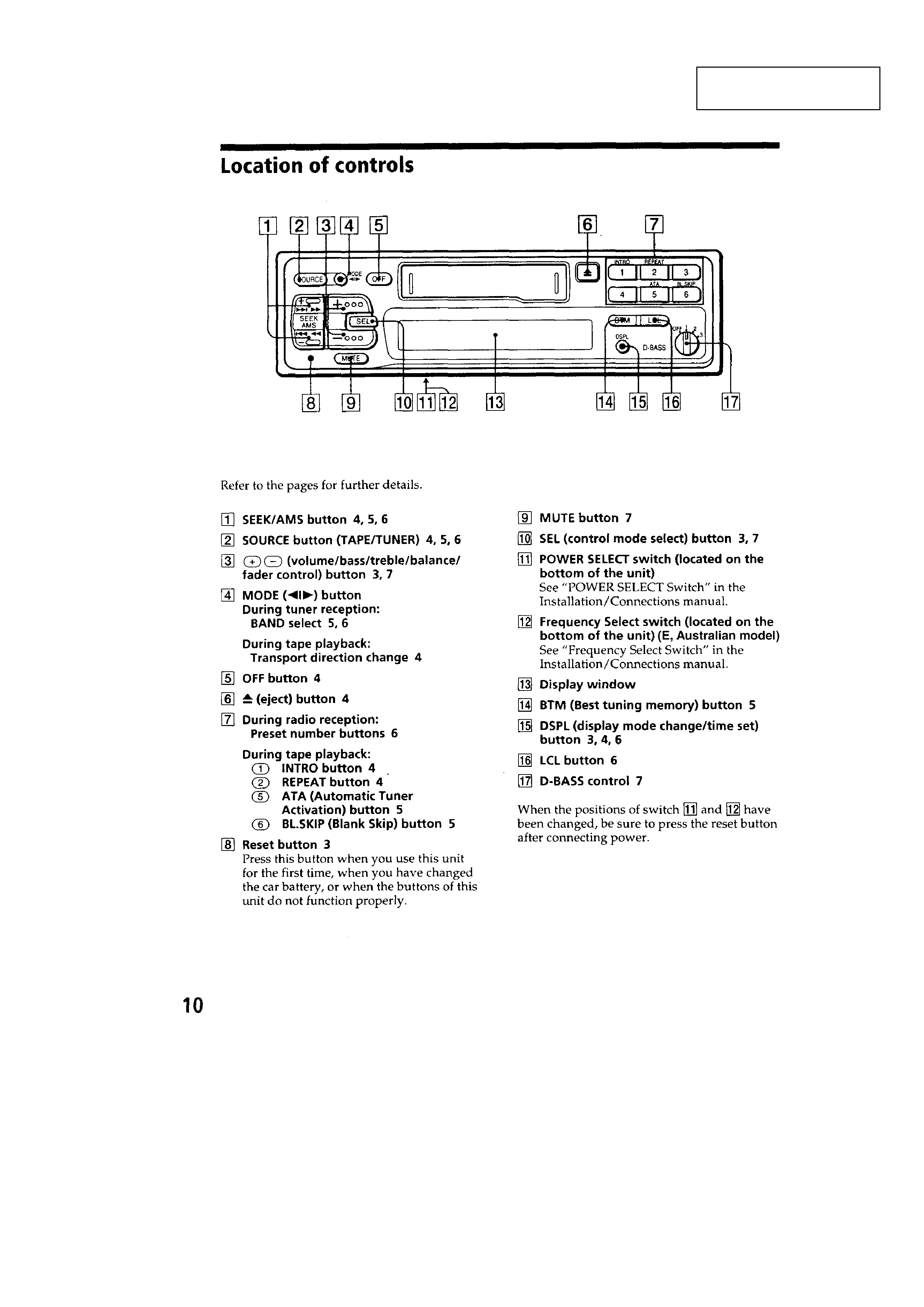
Location of Controls ........................................................ 3
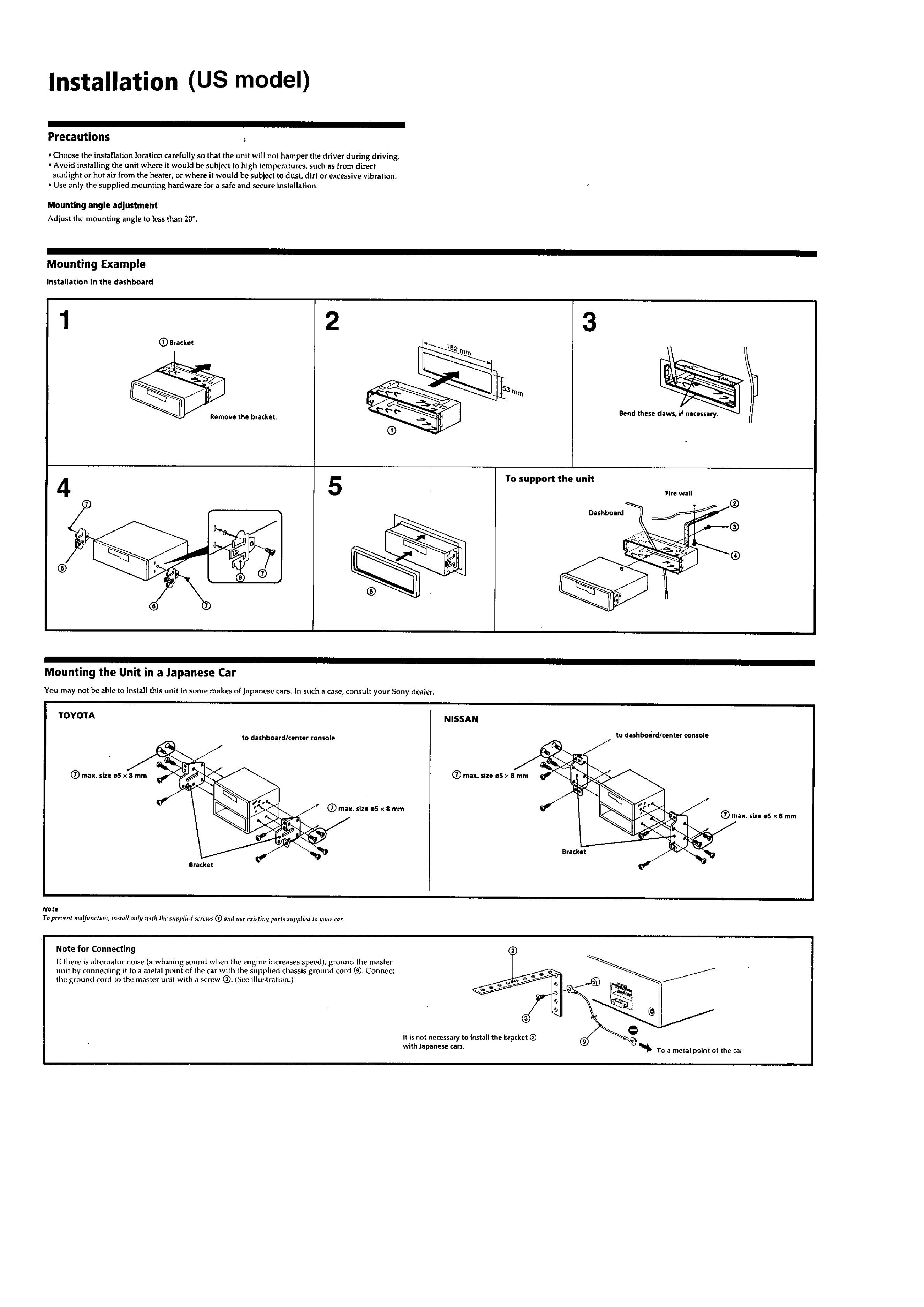
Installation (US Model) ................................................... 4
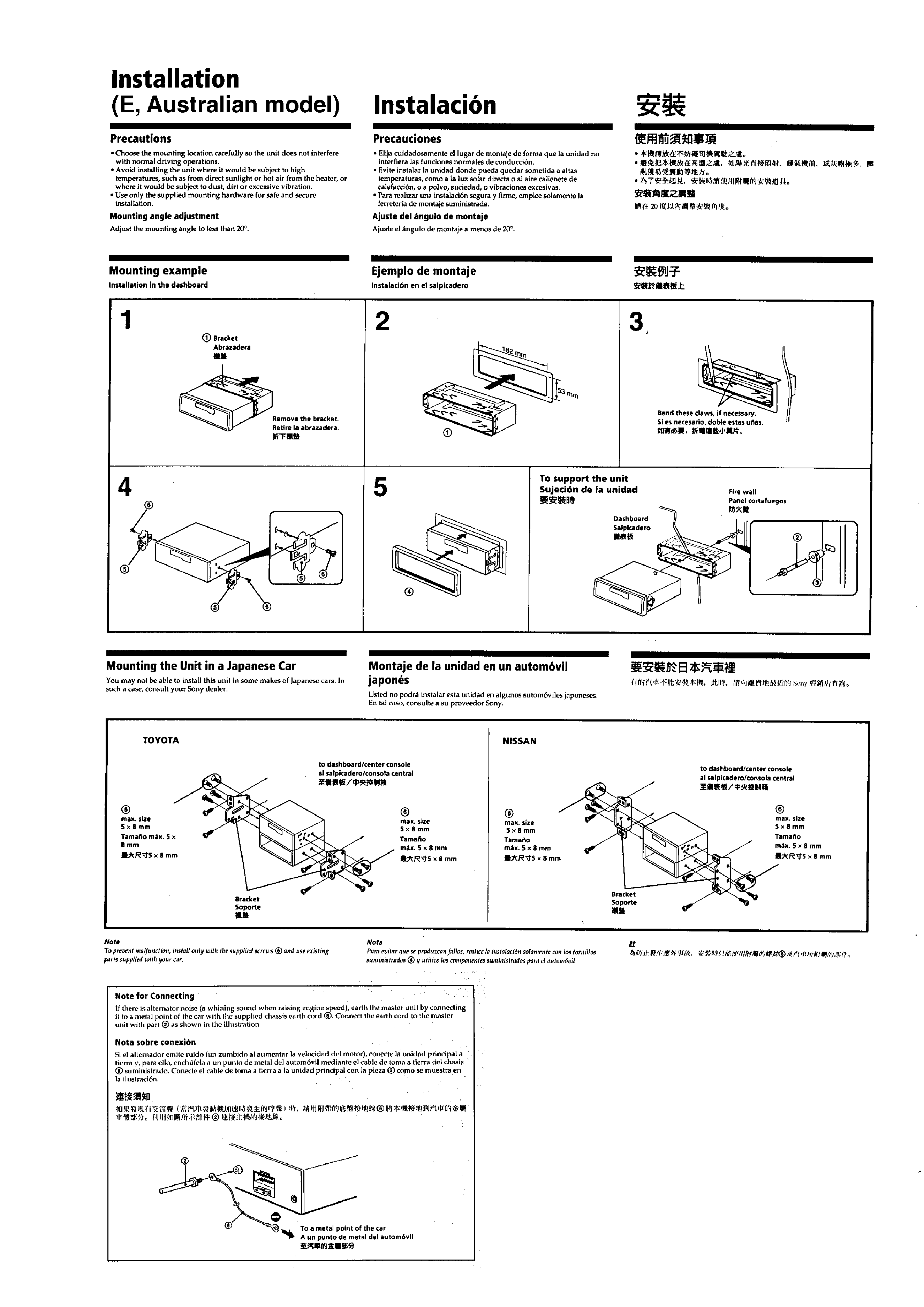
Installation (E, Australian Model) ................................... 5
Connection ....................................................................... 6
2.
DISASSEMBLY .......................................................... 8
3.
ASSEMBLY OF MECHANISM DECK ........... 10
4.
MECHANICAL ADJUSTMENTS ....................... 16
5.
ELECTRICAL ADJUSTMENTS
Tape Deck Section ........................................................... 16
Tuner Section ................................................................... 16
6.
DIAGRAMS
6-1. IC Pin Function Description ............................................ 18
6-2. Printed Wiring Boards MAIN Section ........................ 20
6-3. Schematic Diagram MAIN Section ............................ 23
6-4. Printed Wiring Board CONTROL Section ................. 27
6-5. Schematic Diagram CONTROL Section .................... 29
7.
EXPLODED VIEWS ................................................ 33
8.
ELECTRICAL PARTS LIST ................................ 37
SERVICING NOTES
Flexible Circuit Board Repairing
· Keep the temperature of the soldering iron around 270 ° C dur-
ing repairing.
· Do not touch the soldering iron on the same conductor of the
circuit board (within 3 times).
· Be careful not to apply force on the conductor when soldering
or unsoldering
Notes on chip component replacement
· Never reuse a disconnected chip component.
· Notice that the minus side of a tantalum capacitor may be dam-
aged by heat.
3
SECTION 1
GENERAL
This section is extracted
from instruction manual.
4
5