1
MICROFILM
XM-7557
US Model
Canadian Model
AEP Model
UK Model
E Model
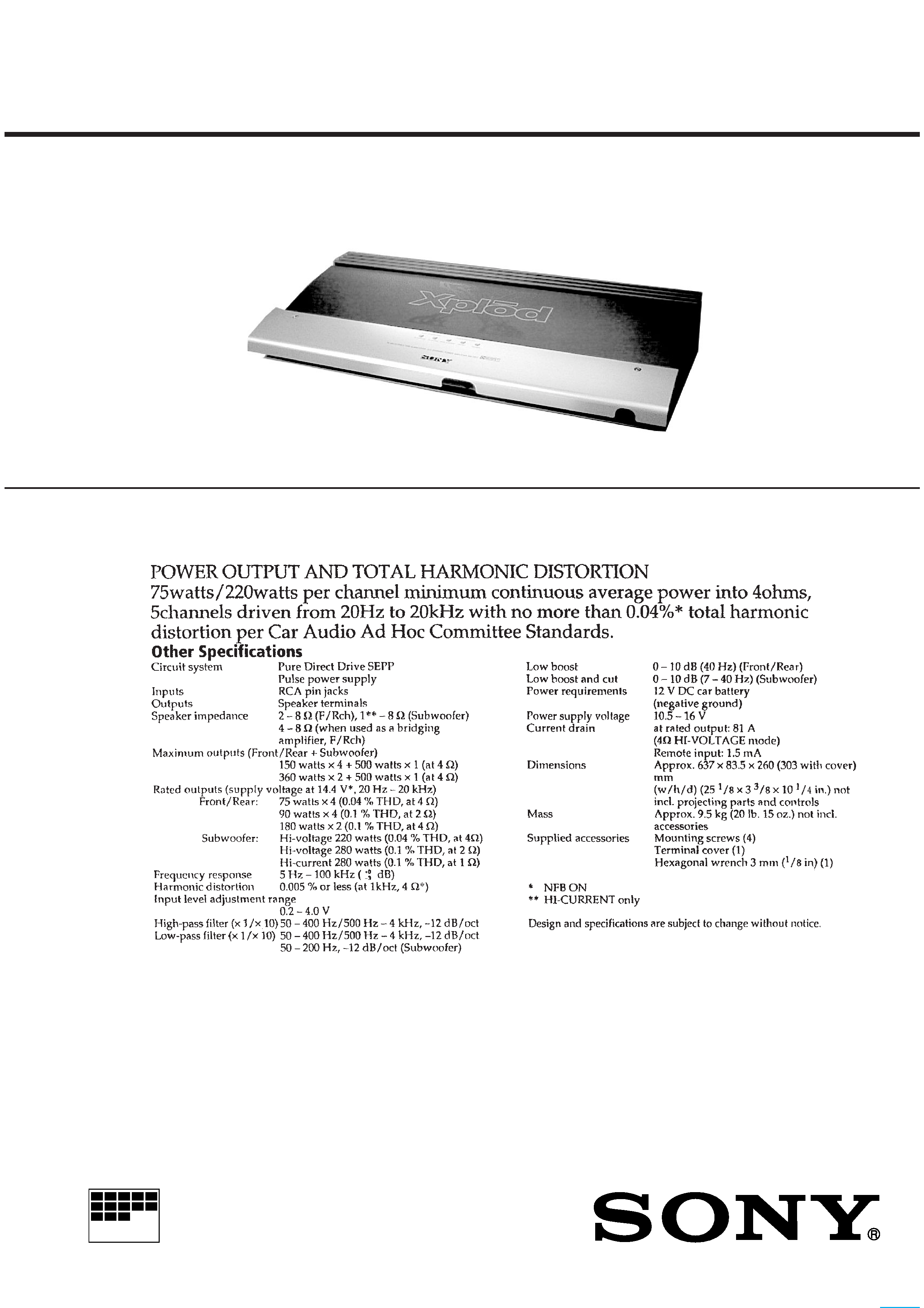
SPECIFICATIONS
SERVICE MANUAL
STEREO POWER AMPLIFER

2
TABLE OF CONTENTS
1. SERVICE MODE ............................................................. 3
2. GENERAL .......................................................................... 4
3. DISASSEMBLY
3-1. Side Plate, Sub 1/Sub 2 and Filer Board ............................... 7
3-2. Amplifier/Power Board and LED Board .............................. 7
4. ELECTRICAL ADJUSTMENT .................................... 7
5. DIAGRAMS
5-1. Block Diagram Amplifier Section .................................. 8
5-2. Block Diagram Power Section ........................................ 9
5-3. Block Diagram Sub 1/Sub 2 Section ............................ 10
5-4. IC Block Diagrams ............................................................. 10
5-5. Printed Wiring Board Filter/Sub 1/Sub 2 Section .......... 11
5-6. Printed Wiring Board Amplifier Section ....................... 12
5-7. Schematic Diagram
Amplifier(1/3)/Filter/Sub 1/Sub 2 Section ..................... 13
5-8. Schematic Diagram/Printed Wiring Board
Amplifier (2/3)/LED/TR Section ................................... 14
5-9. Printed Wiring Board Power Section ............................. 15
5-10. Schematic Diagram
Power/Amplifier (3/3)/TR/LED Section ....................... 17
6. EXPLODED VIEWS
6-1. Plate and Cover Section ...................................................... 18
6-2. Board and Heat Sink ........................................................... 18
7. ELECTRICAL PARTS LIST ........................................ 19
Notes on chip component replacement
· Never reuse a disconnected chip component.
· Notice that the minus side of a tantalum capacitor may be
damaged by heat.
3
SECTION 1
SERVICE NOTE
Clearing the Protector During Repairs
· OVER CURRENT : Detects overcurrent during output.
· OFF SET : Detects DC offset at the speaker terminal.
1. Clearing the OVER CURRENT protector
· When the position of the MODE switch (S801/power board)
is set to HI-CURRENT :
Cut the jumper wire JW230 of the amplifier board.
2. Clearing the OFF SET protector
· Cut the jumper wire JW307 of the amplifier board.
3.
TEST TONE Function
1 Press the TEST TONE button (S710/SUB2 board) with the
power ON. The amplifier is normal if sound is produced from
the speaker.
2 If no sound
: Problem causer by incorrect connecttion of the power supply
system or sperker system.
: The signals input by the RCA cable before the amplifier system
are abnormal.
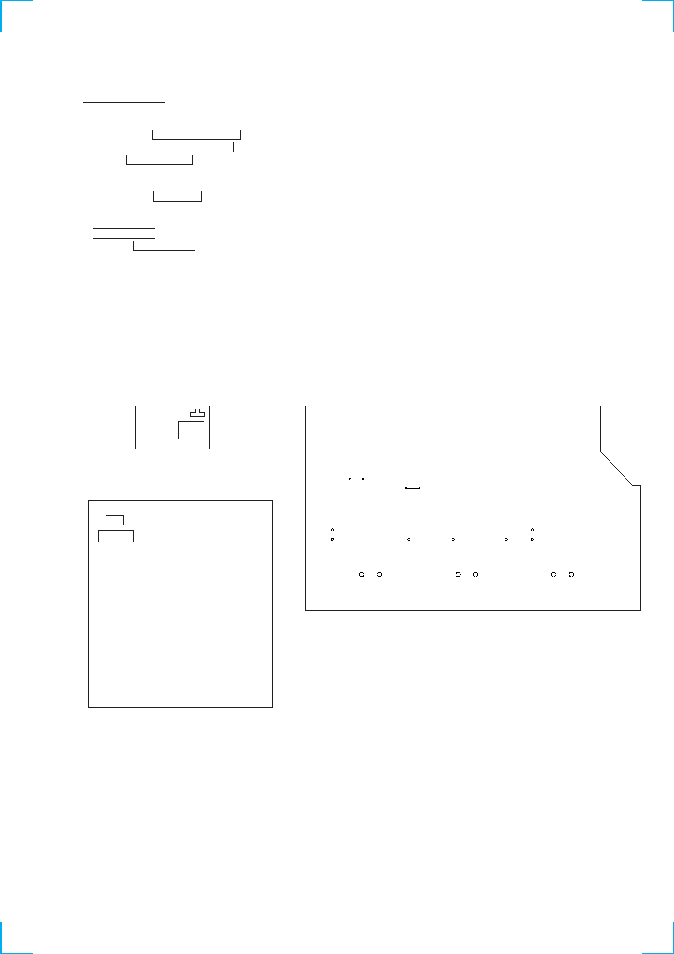
Adjustment Location
TEST
TONE
S710
- SUB 2 BOARD - (Component side)
- AMPLIFIER BOARD - (Component side)
S801
MODE
JW230
JW307
VR502
TP3
TP4
TP5
TP6
TP7
TP1
TP2
VR501
VR401
VR301
VR201
VR101
- POWER BOARD - (Component side)
4
SECTION 2
GENERAL
This section is extracted from
instruction manual.
5