SERVICE MANUAL
MEDIA CENTER/RECEIVER
US Model
E Model
SPECIFICATIONS
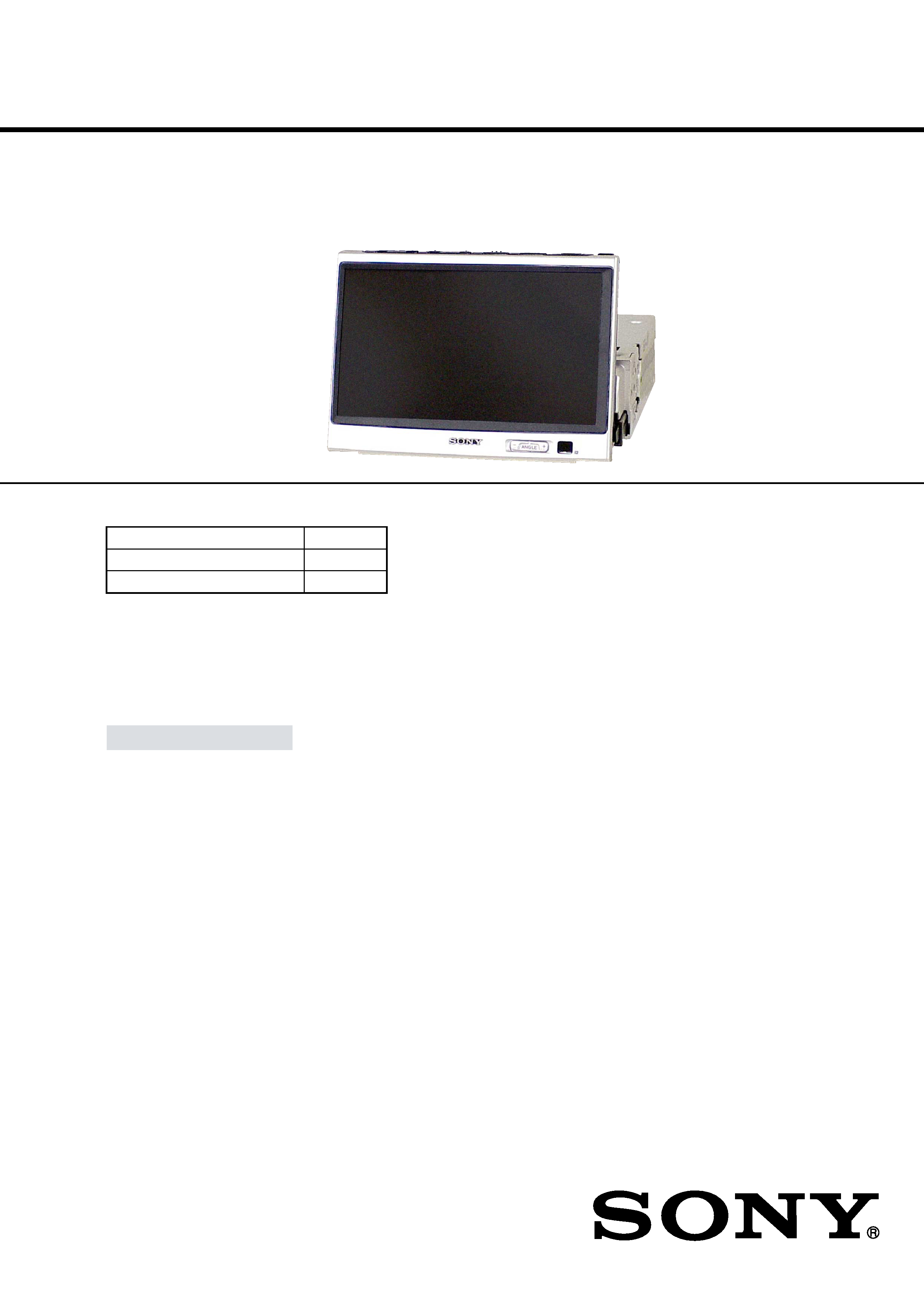
XAV-7W
Ver 1.1 2002.09
9-873-928-02
Sony Corporation
2002I0500-1
e Vehicle Company
C
2002.09
Published by Sony Engineering Corporation
The XAV-7W is composed of the following models.
Media Center
XAV-7W
Connection Box
XA-114
Wireless Remote Commander
RM-X118
AUDIO POWER SPECIFICATIONS (US model)
POWER OUTPUT AND TOTAL HARMONIC DISTORTION
22 watts per channel minimum continuous average power into 4 ohms, 4 channels driven from
20 Hz to 20 kHz with no more than 5 % total harmonic distortion.
General
Power requirements
12 V DC, from car battery (negative
ground)
Inputs
FM/AM antenna (1)
Power supply (1)
Telephone ATT control lead (1)
Illumination control lead (1)
Remote control input connector (1)
Media center/receiver
Monitor section
Display type
Wide LCD color monitor
Size
7 in.
System
TFT active matrix
Number of pixel
336,960 pixels
Tuner section
FM
Tuning range (US model)
87.5 - 107.9 MHz
Intermediate frequency
10.7 MHz
Usable sensitivity
8 dBf
Frequency response
30 - 15,000 Hz
Selectivity
75 dB (400 kHz)
S/N ratio
66 dB (stereo)
72 dB (mono)
Harmonic distortion at 1 kHz
0.6% (stereo)
0.3% (mono)
Separation
35 dB at 1 kHz
AM
Tuning range (US model)
530 - 1,710 kHz
Intermediate frequency
10.7 MHz/450 kHz
Usable sensitivity
30
µV
Amplifier section
Outputs
Speaker outputs
(sure seal connectors)
Speaker impedance
4 - 8 ohms
Maximum power output
45 W
× 4 (into 4 ohms, at 1 kHz)
Tuning range (E model)
FM tuning interval: 50 kHz/200kHz
switchable
87.5 - 108.0 MHz (at 50 kHz step)
87.5 - 107.9 MHz (at 200 kHz step)
Tuning range (E model)
AM tuning interval: 9 kHz/10kHz
switchable
530 - 1,602 kHz (at 9 kHz step)
530 - 1,710 kHz (at 10 kHz step)
Continued on next page

2
XAV-7W
Connection box
Inputs
Video/audio
(Sony bus compatible, 1)
BUS control input connector (1)
Video/audio (2)
Outputs
Video/audio (1)
Connection to main unit
Dedicated 22-pin connector
Dimensions
Approx. 136
× 77 × 30 mm (5 3/8 ×
3 1/8
× 1 3/16 in.) (W × H × D)
Mass
Approx. 260 g (9 oz)
Design and specifications are subject to
change without notice.
Loudness
+8 dB at 100 Hz
+2 dB at 10 kHz
Dimensions
With monitor closed
Approx. 178
× 50 × 185 mm (7 1/8 ×
2
× 7 3/8 in.) (W × H × D)
Mass
Approx. 1.7 kg (3 lb 12 oz)
Supplied accessories
Card remote commander RM-X118
(1) (incl. 1 lithium battery)
Connection box (1)
Parts for installation and
connections (1 set)
Operating Instructions (1 set)
Outputs
Front audio (1)
Rear audio (1)
Subwoofer (mono)
Power antenna relay control lead (1)
Power amplifier control lead (1)
I/O connector
Dedicated 22-pin connector
Tone controls
Bass
±7.5 dB at 100 Hz
Treble
±7.5 dB at 10 kHz
1.
SERVICING NOTES ............................................... 3
2.
GENERAL ................................................................... 5
3.
DISASSEMBLY
3-1. Disassembly Flow ...........................................................
9
3-2. Front Panel Assy .............................................................
9
3-3. Case (Upper) Assy .......................................................... 10
3-4. MAIN Board ................................................................... 11
3-5. Motor Assy (M701) ......................................................... 12
3-6. Setting of Lead from Motor Assy (M701) ..................... 12
3-7. Monitor ............................................................................ 13
3-8. Monitor (F)/(R) Cabinet Assy ......................................... 13
3-9. LCD ................................................................................. 14
3-10. MONITOR Board ........................................................... 14
4.
ASSEMBLY
4-1. Assembly of Flat Cable ................................................... 15
5.
ELECTRICAL ADJUSTMENTS ......................... 16
6.
DIAGRAMS
6-1. Block Diagram MAIN Section ................................ 21
6-2. Block Diagram
DISPLAY/BUS CONTROL Section ........................ 22
6-3. Block Diagram MONITOR Section ........................ 23
6-4. Block Diagram POWER SUPPLY Section ............. 24
6-5. Note for Printed Wiring Boards and
Schematic Diagrams ....................................................... 25
6-6. Schematic Diagram FM/MAIN (1/5) Boards ......... 27
6-7. Schematic Diagram MAIN Board (2/5) .................. 28
6-8. Schematic Diagram MAIN Board (3/5) .................. 29
6-9. Schematic Diagram MAIN Board (4/5) .................. 30
6-10. Schematic Diagram MAIN (5/5)/SYNC Boards .... 31
6-11. Printed Wiring Boards
MAIN (Component Side)/SYNC Boards ................. 32
6-12. Printed Wiring Boards
FM/MAIN (Conductor Side) Boards ....................... 33
6-13. Printed Wiring Board FRONT Board ...................... 34
6-14. Schematic Diagram FRONT Board ......................... 35
6-15. Printed Wiring Board
MONITOR Board (Component Side) ...................... 36
6-16. Printed Wiring Board
MONITOR Board (Conductor Side) ........................ 37
6-17. Schematic Diagram MONITOR Board (1/3) .......... 38
6-18. Schematic Diagram MONITOR Board (2/3) .......... 39
6-19. Schematic Diagram MONITOR Board (3/3) .......... 40
6-20. Printed Wiring Boards ANGLE/KEY Boards ......... 42
6-21. Schematic Diagram ANGLE/KEY Boards ............. 43
6-22. Printed Wiring Board MOTOR Board ..................... 44
6-23. Schematic Diagram MOTOR Board ....................... 45
6-24. Printed Wiring Boards PULSE/SWITCH Boards ... 46
6-25. Schematic Diagram PULSE/SWITCH Boards ........ 46
6-26. IC Pin Function Description ........................................... 52
7.
EXPLODED VIEWS
7-1. Front Panel Section ......................................................... 61
7-2. Case (Upper) Assy Section ............................................. 62
7-3. Open Close Motor Section .............................................. 63
7-4. Case (Lower) Assy Section ............................................. 64
7-5. Monitor Section ............................................................... 65
8.
ELECTRICAL PARTS LIST ............................... 66
TABLE OF CONTENTS
Notes on chip component replacement
·Never reuse a disconnected chip component.
· Notice that the minus side of a tantalum capacitor may be dam-
aged by heat.
3
XAV-7W
SECTION 1
SERVICING NOTES
OPENING AND CLOSING OF THE MONITOR IN
AN ELECTRIC INTERRUPTION STATE
In the state of electric interruption, if a monitor is opened and
closed by force, it will became the cause of failure.
Please open and close a monitor at the time of repair after the
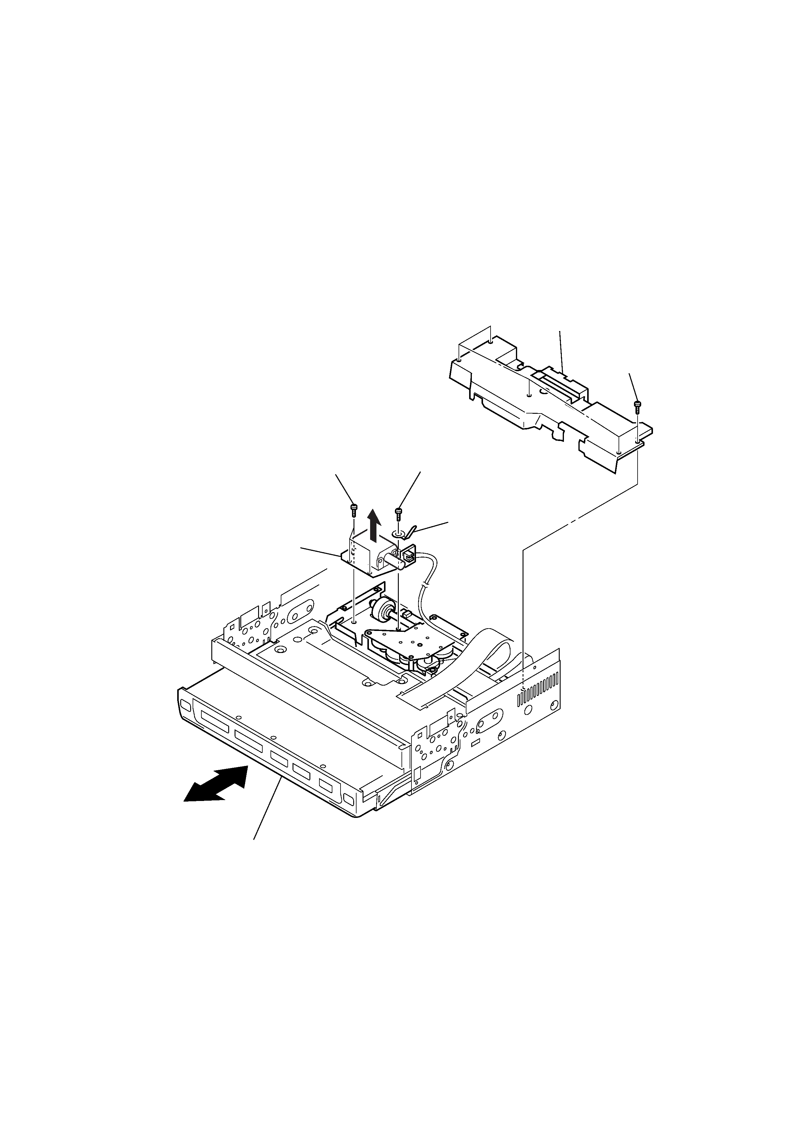
following procedure decomposes and removing a motor.
1) Front Panel Assy (Disassembly page 9)
2) Case (Upper) Assy (Disassembly page 10)
3) Motor Assy (Monitor Open/Close) (M701)
Note: Follow the disassembly procedure in the numerical order given.
1
five screws (M2 × 2.3)
3
three screws (M2 × 2.3)
6
Open and close a monitor after lifting
a motor assy (monitor open/close) (M701).
motor assy (monitor open/close) (M701)
3
screw (M2 × 2.3)
2
cover
4
lug
5
4
XAV-7W
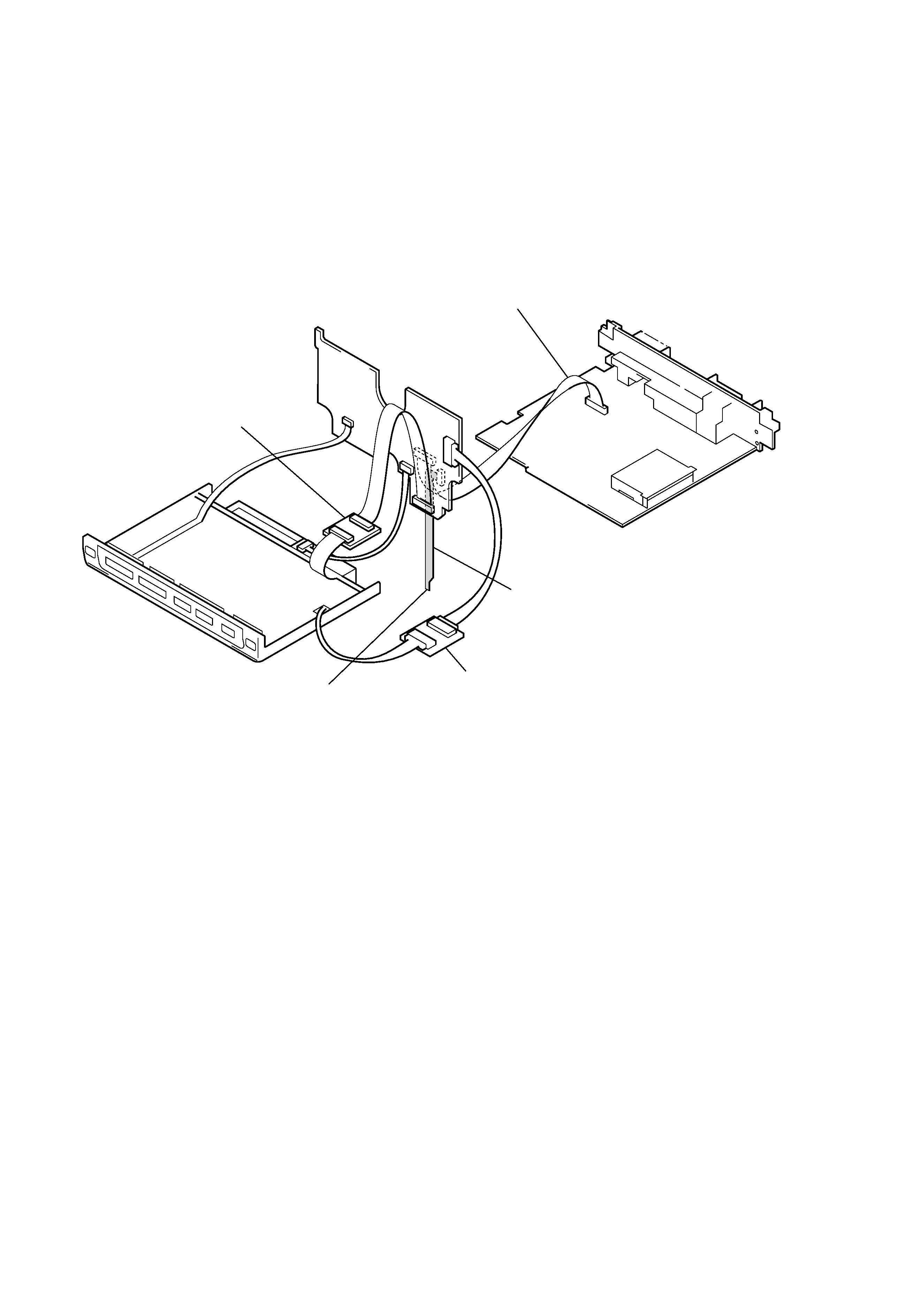
JIG ON REPAIRING
When repairing this set, etc., connect the extension cable as the figure shown below.
extension cable
(LCD unit monitor board)
(Part No. J-2502-051-1)
extension cable
(main board monitor board)
(Part No. J-2502-056-3)
extension cable
(monitor board monitor ground plate)
(Part No. J-2502-056-4)
extension cable
(7 inch monitor back light monitor board)
(Part No. J-2502-051-3)
connect the earth
5
XAV-7W
8
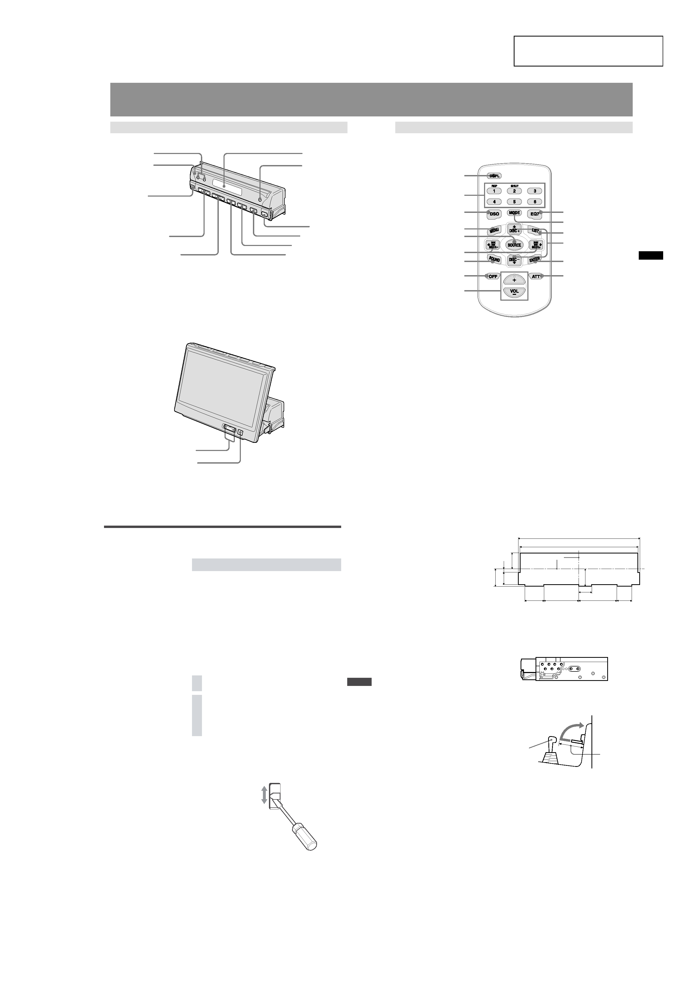
Location of Controls
Main unit
Monitor closed
1
3
2
4
5
6
7
8
9
0
qa
Monitor opened up
1
2
1
DISC /+ buttons
2
Reset button
3
Sensor for card remote commander
4
VOL (volume adjust) /+ buttons
5
SEEK/AMS /+ buttons
1
ANGLE (monitor angle adjust) /+ buttons
2
Sensor for card remote commander
6
Display window
7
OFF (Standby/Power off) button*
8
OPEN/CLOSE button
9
ATT button
0
MODE button
qa
SOURCE (Power on/Radio/CD/MD/VIDEO or TV)
button
* Warning when installing in a car without an ACC (accessory) position on the ignition switch
After turning off the ignition, be sure to press OFF on the unit for 2 seconds to turn off the clock display.
Otherwise, the clock display does not turn off and this causes battery drain.
9
Card remote commander
The unit can be operated with the card remote commander. For safety, stop the car before
using the card remote commander, or have a passenger operate it.
1
2
3
4
5
6
7
8
9
0
qa
qd
qs
qf
qg
1
DSPL (display mode change) button
2
Number buttons
3
DSO button
4
MENU button
5
SOURCE (Power on/Radio/CD/MD/AUX) button
6
B/b SEEK/AMS /+ buttons
7
SOUND button
8
OFF (Standby/Power off) button
9
VOL (volume adjust) +/ buttons
0
EQ7 button
qa
MODE button
qs
LIST button
qd
V/v DISC +/ buttons
qf
ENTER button
qg
ATT button
Note
If the unit is turned off by pressing OFF for 2 seconds, it cannot be operated with the card remote commander unless
SOURCE on the unit is pressed to activate the unit first.
Tip
See "Replacing the lithium battery" for details on how to replace the batteries (page 44).
5
Installation angle
The unit should be installed within an
angle of 25 degrees from horizontal. If
this angle is exceeded, the monitor may
not open up or retract properly.
Note
Keep the units and connection cables
apart.
The Media Center main unit and the
connection box 1 should not be in close
proximity.
1
Installing the Main Unit
Before installation
This unit is designed to be completely safe, but if not installed
correctly, it can cause accidents. Be sure to verify the following
points before installation.
Install the main unit to the in-dash location, and the connection
box under the navigator's seat, etc.
· If the monitor in the opened position is close to a air-
conditioning outlet, the outlet should be closed.
· Install the unit so that the monitor when opened up will not
block access to the hazard switch or other important controls.
·Do not install the unit (monitor) in locations which may be
subject to excessively low or high temperatures. (Otherwise the
unit may be deformed and the LCD may be damaged.)
Exposure to direct sunlight can also lead to high temperatures
and should be avoided.
Selecting the installation location
1 Set the ignition key to OFF or remove it.
2 Place the units in their intended mounting
locations to check the cable length and monitor
installation conditions.
Frequency select switch (E model)
The AM (FM) tuning interval is factory-set to the 9 k (50 k)
position. If the frequency allocation system of your country is
based on 10 kHz (200 kHz) interval, set the switch on the bottom
of the unit to the 10 k (200 k) position before making connections.
FM 200k
AM 10k
FM 50k
AM 9k
6
Cluster panel dimensions
25.5
17.3
6.2
22.5
25
33.6
44.7
55.7
20.6
18
171
175.4
Installation procedure precautions
· Perform the installation carefully. Dropping the unit or
otherwise subjecting it to strong impact or force may deform
the chassis, resulting in failure of the monitor loading
mechanism or other defects.
T/N
T/N T/N
TT
T
N
N
N
·To allow for proper opening and closing of the monitor, there
must be a clearance of at least 147 mm between the closest
position of the gear shift lever and the mounting surface for the
unit.
· In some cases, the gear shift lever may touch the monitor when
moved to a certain position. Make sure that there is no
obstruction to driving operations.
·When installing this unit together with other car audio
equipment (single DIN slot size) in a stacked configuration,
install the Media Center main unit on top.
Gear shift lever
At least 147 mm
(5 7/8 in.) from
mounting surface
Note
If the installation dimensions shown at
right are not observed, the monitor may
not open up smoothly. If this happens,
check the installation once more and
modify the cluster panel where the
dimension requirements are not met. For
some car models, a separately available
mounting kit may be required.
(For details, please consult your dealer.)
Center line
(1
1 /
16
)
(1
/4
)
(11
/16
)
(29
/32
)
(7)
(6 3/4)
(1 3/8)
(1 13/16)
(22/32)
(1)
(2 1/4)
(13/16)
Unit: mm (inch)
SECTION 2
GENERAL
This section is extracted from
instruction manual.