
Operating Instructions
1999 by Sony Corporation
WX-C55
Changer Control
Audio Master
US
For installation and connections, see the supplied installation/connections
manual.
Owner's Record
The model and serial numbers are located on the bottom of the unit.
Record the serial number in the space provided below.
Refer to these numbers whenever you call upon your Sony dealer
regarding this product.
Model No. WX-C55 Serial No.

2
Welcome !
Thank you for purchasing the Sony Changer
Control Audio Master. This unit lets you enjoy
a variety of features as well as an optional
rotary commander.
In addition to the CD playback, tape playback
and radio operations, you can expand your
system by connecting an optional MD/CD
unit*.
* You can connect a CD changer, an MD changer, a
CD player and an MD player.
Warning
This equipment has been tested and found to
comply with the limits for a Class B digital
device, pursuant to Part 15 of the FCC Rules.
These limits are designed to provide
reasonable protection against harmful
interference in a residential installation. This
equipment generates, uses, and can radiate
radio frequency energy and, if not installed
and used in accordance with the instructions,
may cause harmful interference to radio
communications. However, there is no
guarantee that interference will not occur in a
particular installation. If this equipment does
cause harmful interference to radio or
television reception, which can be determined
by turning the equipment off and on, the user
is encouraged to try to correct the interference
by one or more of the following measures:
- Reorient or relocate the receiving antenna.
- Increase the separation between the
equipment and receiver.
- Connect the equipment into an outlet on a
circuit different from that to which the
receiver is connected.
- Consult the dealer or an experienced radio/
TV technician for help.
You are cautioned that any changes or
modifications not expressly approved in this
manual could void your authority to operate
this equipment.
CAUTION
The use of optical instruments with this
product will increase eye hazard.

3
Table of Contents
This Unit Only
Location of controls ................................................. 4
Getting Started
Resetting the unit ................................................ 6
Using the dummy cover .................................... 6
Setting the clock .................................................. 6
CD Player
Listening to a CD ................................................ 7
Playing a CD in various modes ........................ 8
Cassette Player
Listening to a tape ............................................... 8
Playing a tape in various modes ....................... 9
Radio
Memorizing stations automatically
-- Best Tuning Memory (BTM) ................. 10
Memorizing only the desired stations ........... 10
Receiving the memorized stations ................. 10
Other Functions
The rotary commander labels ......................... 11
Using the rotary commander .......................... 12
Adjusting the sound characteristics ............... 13
Changing the sound and beep tone ............... 14
Selecting the spectrum analyzer ..................... 14
With Optional Equipment
CD/MD unit
Playing a CD or MD ......................................... 15
Playing tracks repeatedly
-- Repeat Play .............................................. 15
Playing tracks in random order
-- Shuffle Play ............................................. 16
Additional Information
Precautions ......................................................... 16
Maintenance ....................................................... 18
Specifications ..................................................... 19
Troubleshooting guide ..................................... 20
4
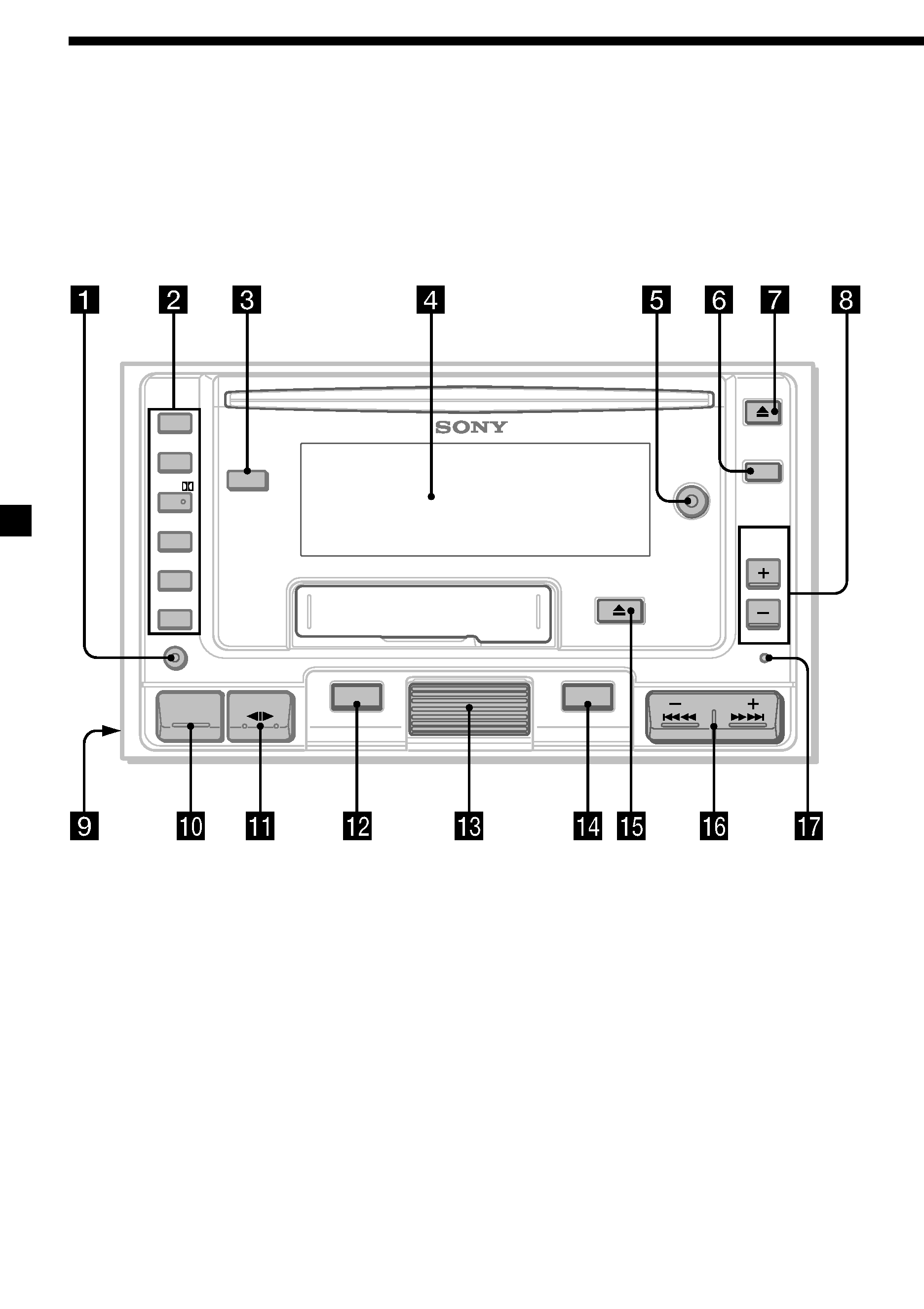
Location of controls
CD
TAPE
DISC
PRESET/
REPEAT
D-BASS
SOUND
SHUF/
METAL
ATA
BL SKIP
DSPL
SENS
BTM
1
2
3
4
5
6
SA
MODE
OFF
SEEK/AMS
SOURCE

5
Refer to the pages for details.
1 SENS/BTM (sensitivity adjust/best
tuning memory) button 10, 11
2 During tuner reception:
Preset number buttons 10
During tape/CD/MD playback:
(2) REPEAT button 8, 9, 15
(3) SHUF/; (Shuffle/Dolby) button
8, 9, 16
(4) METAL button 9
(5) ATA (Automatic Tuner Activation)
button 9
(6) BL SKIP (Blank Skip) button 9
3 SA (Spectrum Analyzer) button 14
4 Display window
5 D-BASS button 14
6 OFF button 7, 8
7 CD Z (eject) button 7
8 PRESET/DISC button
During radio reception:
Preset station search 11
During CD/MD playback:
Disc select 15
9 POWER SELECT switch (located on the
left side of the unit)
See "POWER SELECT Switch" in the
Installation/Connections manual.
0 SOURCE (source select) button 7, 8, 10,
15
qa MODE/o (band/unit select/tape
transport direction change) button
8, 10, 15
qs DSPL (display mode change) button
6, 7, 9, 11, 15
qd Jog roller (volume/bass/treble/balance/
fader) 6, 13
Jog roller usually functions as a volume
control except in some adjusting modes.
qf SOUND button 6, 13
qg TAPE Z (eject) button 8
qh SEEK/AMS (seek/Automatic Music
Sensor/manual search) button 8, 9, 10,
11, 15
qj Reset button 6
When the positions of switch 9 has been
changed, be sure to press the reset button after
connecting power.