SERVICE MANUAL
RADIO CASSETTE PLAYER
Canadian Model
AEP Model
UK Model
Australian Model
WM-FX673
E Model
WM-FX673/FX877
Chinese Model
Tourist Model
WM-FX877
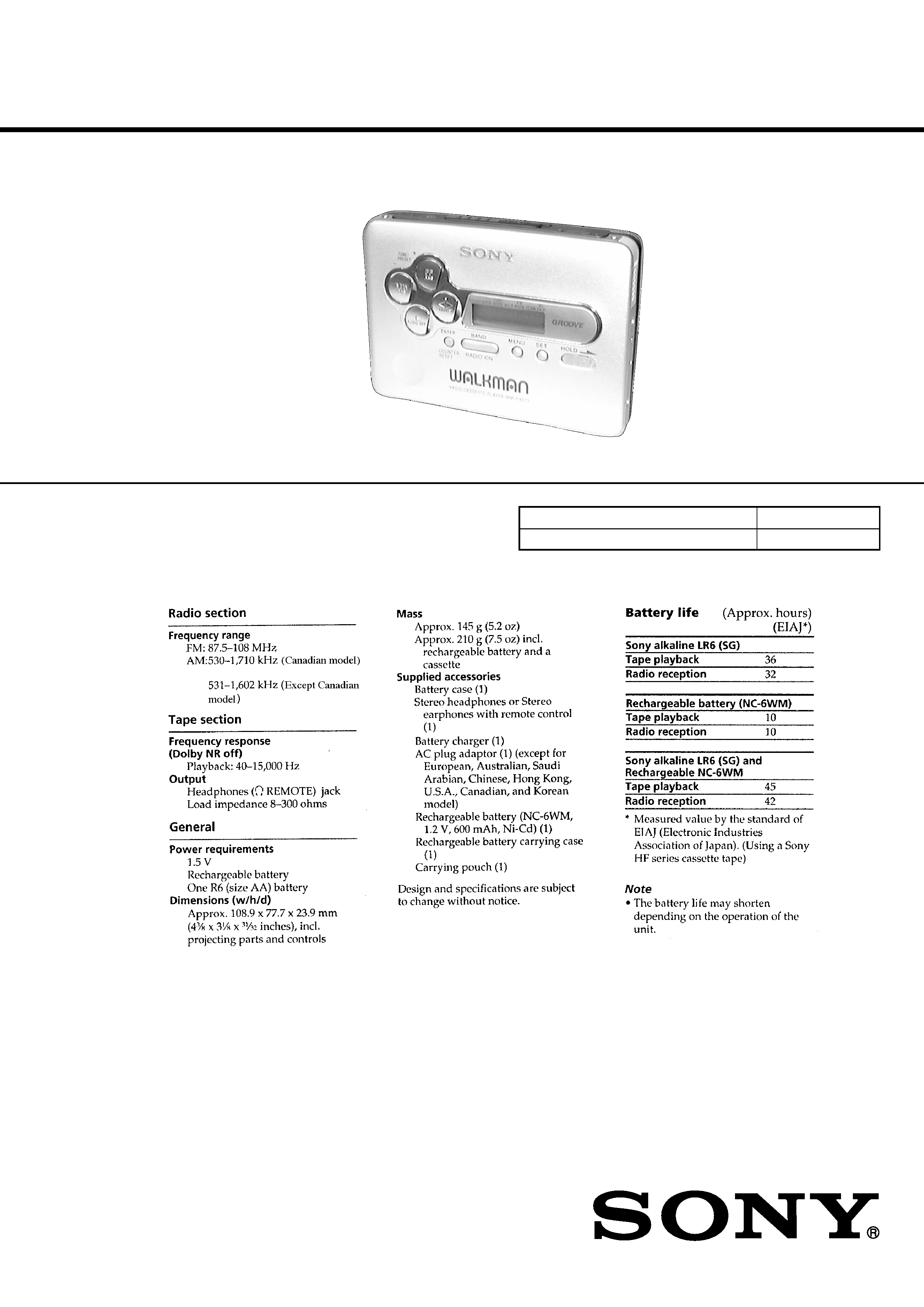
SPECIFICATIONS
WM-FX673/FX877
Photo: WM-FX673
Dolby noise reduction manufactured under license
from Dolby Laboratories Licensing Corporation.
"DOLBY" and the double-D symbol
a are trade-
marks of Dolby Laboratories Licensing Corporation.
Model Name Using Similar Mechanism
WM-EX670/EX672
Tape Transport Mechanism Type
MT-WMEX672-162
Ver 1.2 2001. 11
9-926-973-12
Sony Corporation
2001K0500-1
Personal Audio Company
C
2001.11
Published by Sony Engineering Corporation

2
TABLE OF CONTENTS
1.
SERVICING NOTES ............................................... 3
2.
GENERAL ................................................................... 5
3.
DISASSEMBLY ......................................................... 7
4.
MECHANICAL ADJUSTMENTS ....................... 12
5.
ELECTRICAL ADJUSTMENTS ......................... 12
6.
DIAGRAMS
6-1. Block Diagram TUNER Section ............................. 15
6-2. Block Diagram MAIN Section ................................. 17
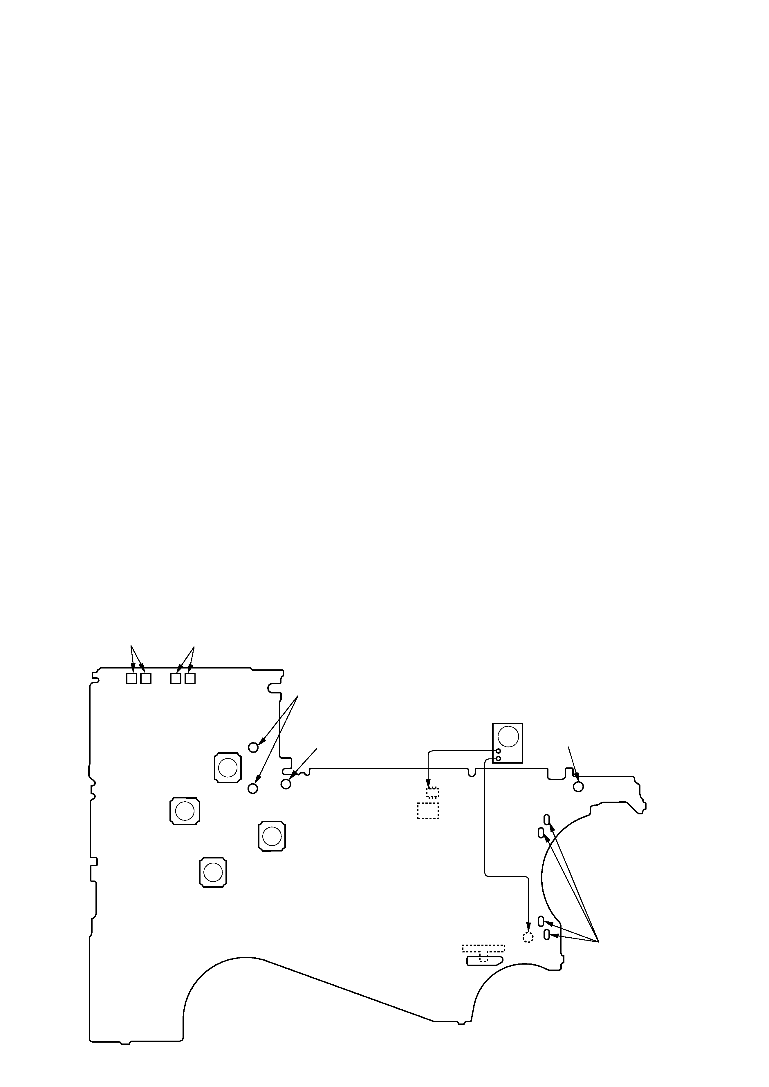
6-3. Printed Wiring Board ...................................................... 19
6-4. Schematic Diagram ......................................................... 23
6-5. IC Pin Function Description ........................................... 30
7.
EXPLODED VIEWS ................................................ 32
8.
ELECTRICAL PARTS LIST ............................... 34
Flexible Circuit Board Repairing
· Keep the temperature of the soldering iron around 270 °C dur-
ing repairing.
· Do not touch the soldering iron on the same conductor of the
circuit board (within 3 times).
· Be careful not to apply force on the conductor when soldering
or unsoldering.
Notes on chip component replacement
· Never reuse a disconnected chip component.
· Notice that the minus side of a tantalum capacitor may be dam-
aged by heat.
ATTENTION AU COMPOSANT AYANT RAPPORT
À LA SÉCURITÉ!
LES COMPOSANTS IDENTIFIÉS PAR UNE MARQUE
!
SUR LES DIAGRAMMES SCHÉMATIQUES ET LA LISTE
DES PIÈCES SONT CRITIQUES POUR LA SÉCURITÉ
DE FONCTIONNEMENT. NE REMPLACER CES COM-
POSANTS QUE PAR DES PIÈCES SONY DONT LES
NUMÉROS SONT DONNÉS DANS CE MANUEL OU
DANS LES SUPPLÉMENTS PUBLIÉS PAR SONY.
SAFETY-RELATED COMPONENT WARNING!!
COMPONENTS IDENTIFIED BY MARK
! OR DOTTED
LINE WITH MARK
! ON THE SCHEMATIC DIAGRAMS
AND IN THE PARTS LIST ARE CRITICAL TO SAFE
OPERATION. REPLACE THESE COMPONENTS WITH
SONY PARTS WHOSE PART NUMBERS APPEAR AS
SHOWN IN THIS MANUAL OR IN SUPPLEMENTS PUB-
LISHED BY SONY.
3
SECTION 1
SERVICING NOTES
This set detects the rotation of the idler gear (A) (side S) using the
PH1 (photo reflector). The PH1 is mounted on the MAIN board,
therefore the idler gear (A) (side S) cannot be detected with the
MAIN board removed. As a result, the motor (M601) cannot be
controlled, causing malfunction.
Further, the DIRECTION switch (S1) is also mounted on the MAIN
board, and with the board removed, the mechanism position can-
not be detected and the operation is not changed over.
Therefor, when the voltage check is executed with the MAIN board
removed, follow the procedure provided below.
1. Setting
(1)
Refer to "3. DISASSEMBLY", and remove the MAIN board.
(2)
Connect the MAIN board to the motor (M601) and the
plunger (PM901) using jumper wires. These can be connected
easily with the use of the extension tool (Part No. 1-769-
143-11) (ten in one set).
(3)
Short the TAPE DETECT switch (S901-1) terminals and the
ATS switch (S901-2) terminals.
(4)
Connect the AF oscillator to the Q15-1 (COLLECTOR) and
the TP23 (GND).
(5)
Supply 1.3 V to the battery terminals using the regulated
power supply.
2. Preset state
To set the PLAY, FF, REW modes, the preset state must be set.
(1)
Check that the slider (NR) and the DIRECTION switch (S1)
are set to the center position. If not, set the preset state as
follow.
(2)
Move the DIRECTION switch (S1) to the side, which the
slider (NR) is facing.
(3)
The slider (NR) will move when the regulated power supply
switch is set to OFF once and then set to ON. Move the DI-
RECTION switch (S1) according to this timing and set to
the center position.
3. FF, REW modes
(1)
Check that the preset state is set.
(2)
Input the square wave or sine wave to the Q15-1 (COLLEC-
TOR) and the TP23 (GND).
(3)
Press the [ RADIO OFF] button (S3) to set the STOP mode.
(4)
Press the [FF AMS] button (S4) or the [REW AMS] button
(S5).
4. PLAY mode
(1)
Check that the preset state is set.
(2)
Input the square wave or sine wave to the Q15-1(COLLEC-
TOR) and the TP23 (GND).
(3)
Press the [ RADIO OFF] button (S3) to set the STOP mode.
(4)
Press the [ REPEAT] button (S9) will move the slider
(NR) once towards the side R and then to the side F. Move
the DIRECTION switch (S1) according to this timing will
set the PLAY mode (side F). Press the [ REPEAT]
button (S9) another time and move the DIRECTION switch
(S1) according to the movement of the slider (NR) will set
the PLAY (R mode).
Note 1: If the above fails, perform from preset again.
Note 2: Use the [ REPEAT] (S9)
, [ RADIO OFF] (S3),
[FF AMS] (S4), and [REW AMS] (S5) buttons on the remote
controller as much as possible. If no remote controller, do not
touch the buttons with your hands, but using a stick with a round
tip.
Note 3: When using headphones, the timing for move the DIRECTION
switch (S1) can be determined from the beep sound.
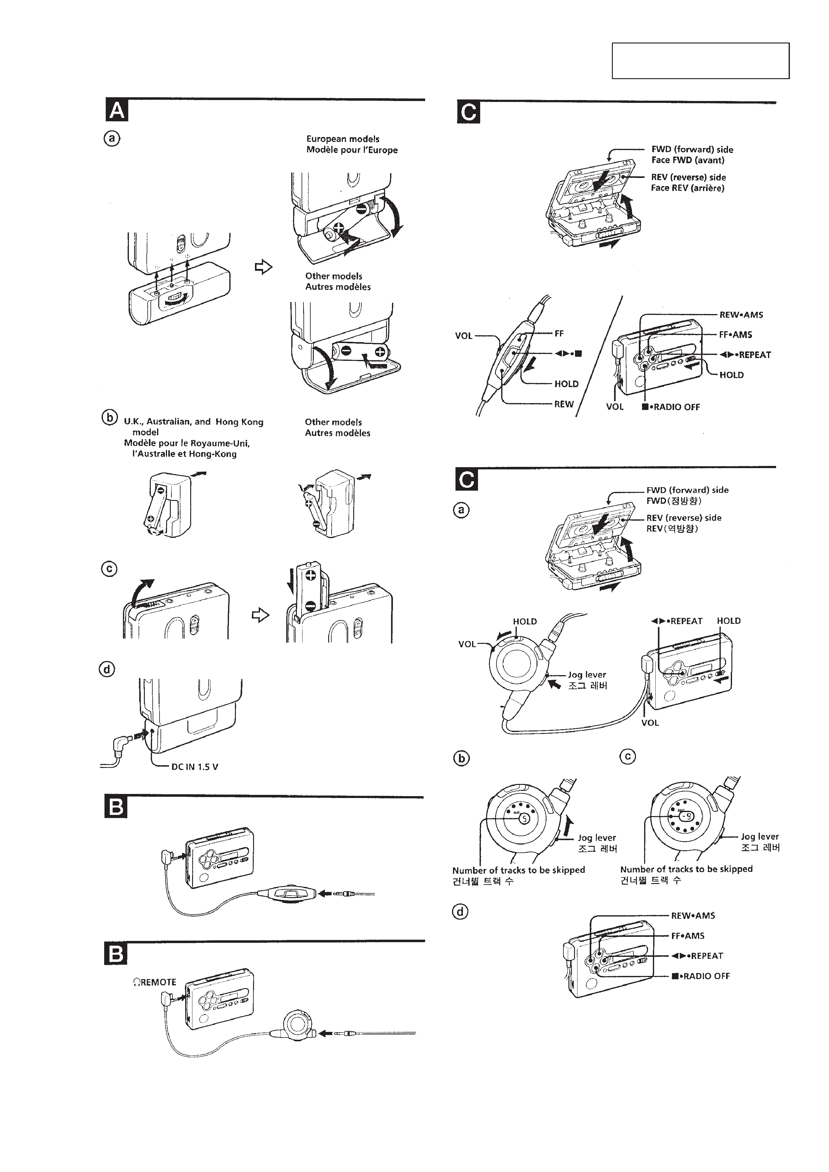
9 (
9 (
9 (
p
p
p
+
FF AMS
(S4)
connect to the plunger
(PM901)
battery
terminal
'
battery
terminal
`
square wave
(sine wave)
10 Hz, 3.5 dB
AF oscillator
TAPE DETECT
(S901-1)
MAIN Board (side B)
ATS
(S901-2)
REW AMS
(S5)
TP23
(GND)
S1
DIRECTION
FWDNSTOPnREV
oe
REPEAT
(S9)
p
RADIO OFF
(S3)
PH1
Q15
connect to the
motor (M601)
4
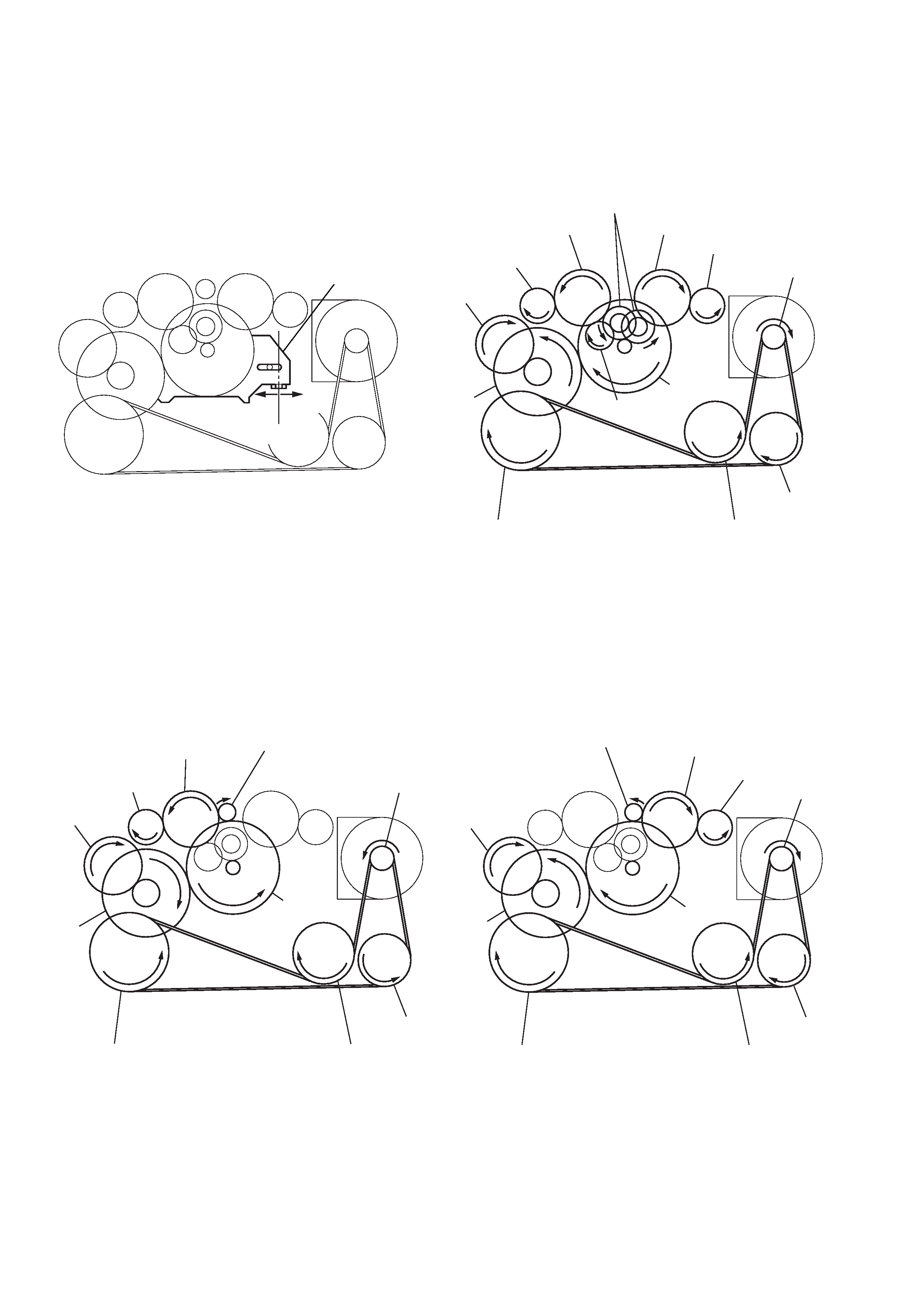
Slider (NR)
Rotation system
Rotation system during PLAY.
Rotation system during FF.
Rotation system during REW.
slider (NR)
side F side R
center
insert flywheel (N)
insert flywheel (R)
reverse pulley
clutch assy (F)
gear (Y)
cam gear
gear (REEL) (side T)
motor pulley
idler gear (A) (side T)
gear (FR)
(FF: left side)
insert flywheel (N)
insert flywheel (R)
reverse pulley
clutch assy (F)
idler gear (B)
gear (Y)
cam gear
gear (REEL) (side T)
gear (REEL) (side S)
motor pulley
idler gear (A) (side T)
idler gear (A) (side S)
gear (NR)
(FWD : left side/
REV : right side)
insert flywheel (N)
insert flywheel (R)
reverse pulley
clutch assy (F)
gear (Y)
cam gear
gear (REEL)
(side S)
motor pulley
idler gear (A)
(side S)
gear (FR)
(REW: right side)
5
SECTION 2
GENERAL
This section is extracted from
instruction manual.
(FX673)
(FX877)
(FX673)
(FX877)