RADIO CASSETTE PLAYER
E Model
Tourist Model
Model Name Using Similar Mechanism
NEW
Tape Transport Mechanism Type
MT-WMEX655-125
SPECIFICATIONS
SERVICE MANUAL
WM-FX855
Dolby noise reduction manufactured under license from
Dolby Laboratories Licensing Corporation.
" DOLBY " and the double-D symbol
a are trademarks of
Dolby Laboratories Licensing Corporation.
Photo: Black
Continued on next page
Tape player section and general
Frequency response (
aNR switch off)
3018,000 Hz
Output
Headphones (
2 REMOTE jack)
Load impedance 8300 ohms
Power output
3mW + 3mW at DC operation
Power requirements
1.5V DC
Rechargeable battery (NC-6WM), 1.2 V, 600mAh, Ni-Cd One R6
(size AA) battery
Battery life (Approx. hours)
Rechargeable NC-6WM
Fully charged
Playback
9
Radio/TV reception
9
Sony alkaline LR6 (WM)
Playback
36
Radio/TV reception
29
Sony R6P (SR)
Playback
10
Radio/TV reception
9
Rechargeable NC-6WM
Sony alkaline LR6 (WM)
Used together
Playback
45
Radio/TV reception
36
Dimensions
Approx. 108.7
× 80.0 × 23.5 mm (w/h/d)
Weight
Approx. 150 g (Main unit)
Approx. 210 g (incl. Headphones with remote control, Recharge-
able battery NC-6WM, Tape (C-60HF)
Radio section
Frequency range
Tourist model
FM : 7690MHz
AM : 5311,710kHz
TV : 112ch (Except Korean model.)
Korean model (Area setting : Eur)
FM : 87.5108MHz
AM : 5311,602kHz
Design and specifications are subject to change without notice.
Ver 1.3 2001.11
9-923-252-12
Sony Corporation
2001K0500-1
Personal Audio Company
C
2001.11
Published by Sony Engineering Corporation

2
TABLE OF CONTENTS
1.
SERVICE NOTE ....................................................... 3
2.
GENERAL ................................................................... 5
3.
DISASSEMBLY ......................................................... 6
4.
MECHANICAL ADJUSTMENT .......................... 8
5.
ELECTRICAL ADJUSTMENT ............................ 8
6.
DIAGRAMS
6-1. Block Diagram ................................................................ 11
6-2. Printed Wiring Board
AUDIO Section ......................................................... 14
6-3. Schematic Diagram
AUDIO Section ......................................................... 17
6-4. Schematic Diagram
TUNER Section ........................................................ 22
6-5. Printed Wiring Board
TUNER Section ........................................................ 25
6-6. IC Pin Function Description ........................................... 30
7.
EXPLODED VIEWS ................................................ 34
8.
ELECTRICAL PARTS LIST ............................... 37
Notes on chip component replacement
· Never reuse a disconnected chip component.
· Notice that the minus side of a tantalum capacitor may be dam-
aged by heat.
Flexible Circuit Board Repairing
· Keep the temperature of the soldering iron around 270 °C dur-
ing repairing.
· Do not touch the soldering iron on the same conductor of the
circuit board (within 3 times).
· Be careful not to apply force on the conductor when soldering
or unsoldering
SAFETY-RELATED COMPONENT WARNING!!
COMPONENTS IDENTIFIED BY MARK
! OR DOTTED
LINE WITH MARK
! ON THE SCHEMATIC DIAGRAMS
AND IN THE PARTS LIST ARE CRITICAL TO SAFE
OPERATION. REPLACE THESE COMPONENTS WITH
SONY PARTS WHOSE PART NUMBERS APPEAR AS
SHOWN IN THIS MANUAL OR IN SUPPLEMENTS PUB-
LISHED BY SONY.
3
SECTION 1
SERVICE NOTE
Service Mode
Mode for operating the mechanism section with the AUDIO board
opened.
1. Setting
1) Refer to "Disassembly", and remove the cabinet and open the
AUDIO board.
2) Connect the motor and plunger to the AUDIO board using
jumper wires. These can be connected easily with the use of
the extension tool (1-769-143-11) (ten in one set).
3) Turn ON the HOLDER switch (S706).
4) Input the square wave or sine wave to PH701. (See right fig-
ure.)
5) Supply 1.5 V to the
` and ' terminals of the battery using a
regulated power supply.
2. Preset state
To set the PLAY, FF, REW modes, the preset state must be set.
1) Check that the lever (FR SW) and FWD/RVS switch (S708)
are set to the center position. If not, set the preset state as fol-
lows.
2) Move the FWD/RVS switch (S708) to the side which the lever
(FR SW) is facing.
3) The lever (FR SW) will move when the regulated power sup-
ply switch is set to OFF once and then set to ON. Move the
FWD/RVS switch (S708) according to this timing and set to
the center position.
3. FF, REW Modes
1) Check that the preset state is set and press the FF and REW
switches.
4. PLAY mode
1) Check that the preset state is set.
2) Pressing the
ª · switch will move the lever (FR SW) once
towards the F side and then to the R side. Moving the FWD/
RVS switch (S708) according to this timing will set the PLAY
mode (R side). Pressing the
ª · switch another time and
moving the FWD/RVS switch (S708) according to the move-
ment of the lever (FR SW) will set the PLAY ( F side) mode.
Note 1: If the above fails, perform from preset again.
Note 2: Use the
ª ·, , FF, REW switches on the remote
commander as much as possible. If no remote commander,
do not touch the switches with your hands, but using a
stick with a round tip.
Note 3: When using headphones, the timing for moving the S708
can be determined from the beep sound.
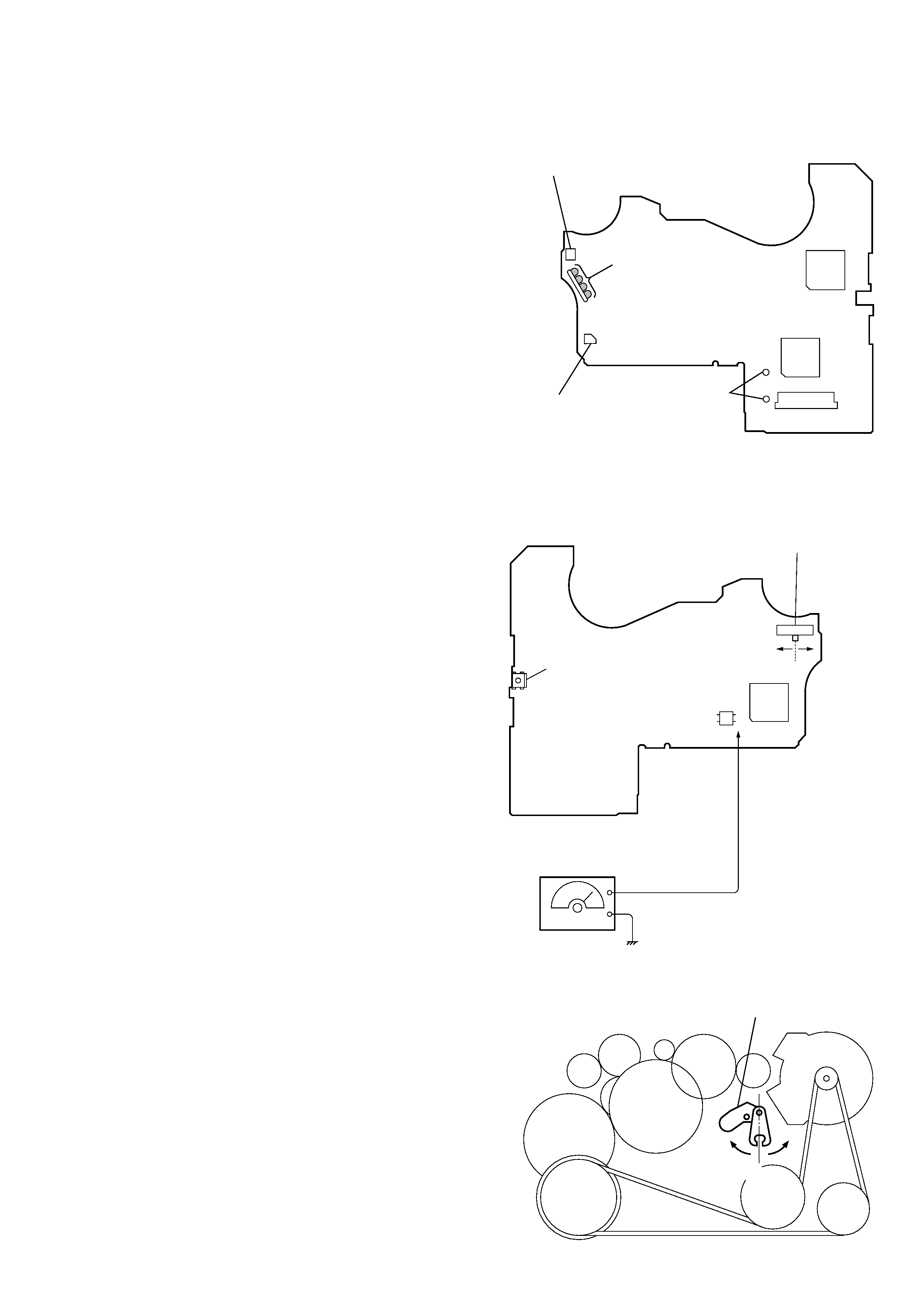
Audio Board
-- Side A
Battery terminal (--)
Connect to motor
Connect to plunger
CN501
IC501
IC301
Battery
terminal (+)
-- Side B --
S708
FWD/RVS Switch
(FWD
STOP RVS)
S706
(HOLDER Switch)
side F
side R
Center
IC701
PH701
AF OSCILLATOR
Sguare wave
(Sine wave)
10 Hz --3.5 dB
AK
C
E
lever (FR SW)
side F
side R
center
Lever (FR SW)
4
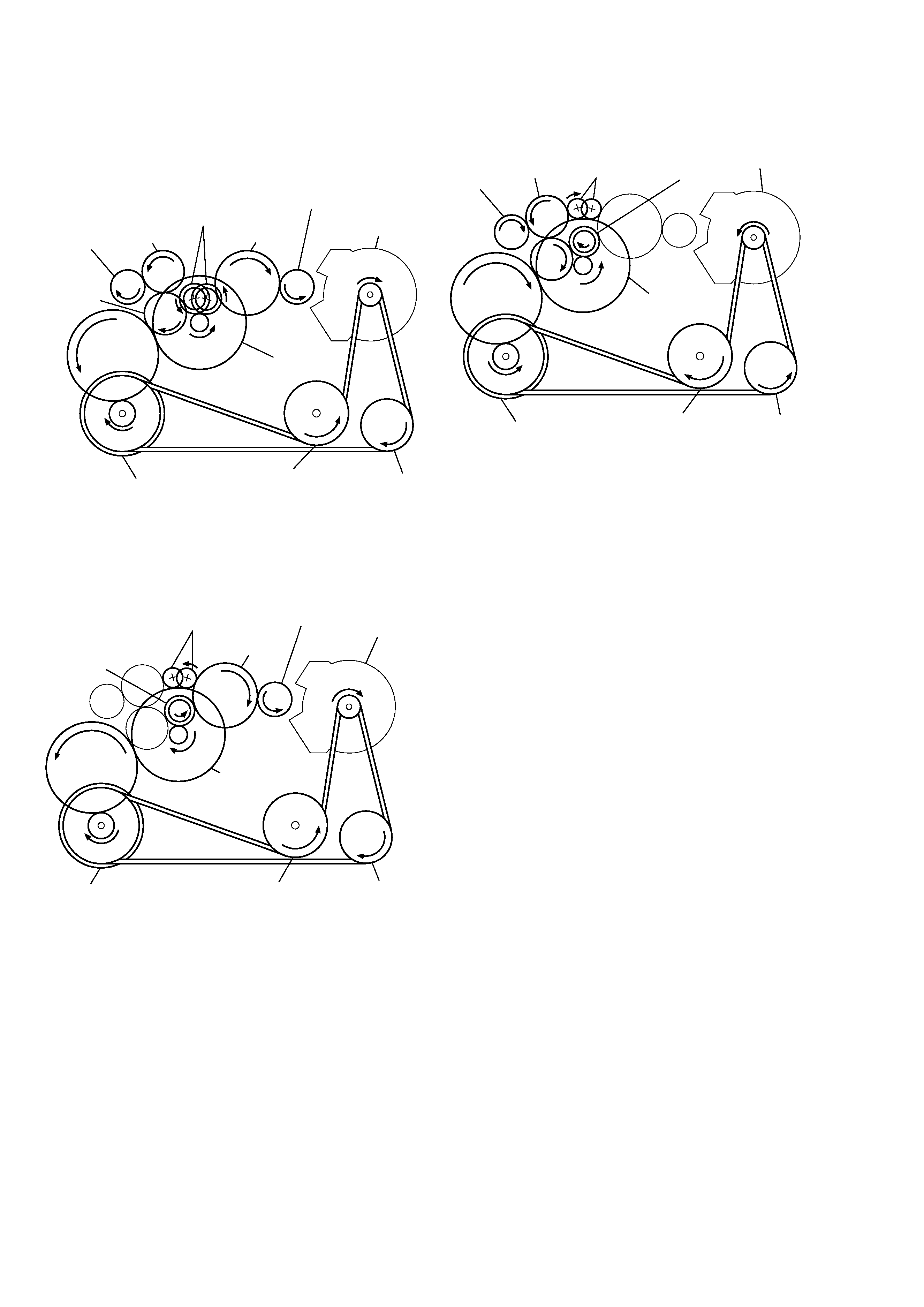
Rotation system
Rotation system during PLAY.
gear (REEL)
(T side)
gear (TB)
gear (S)
clutch ass'y (M)
gear (Y)
gear (TA)
pulley (reverse)
flywheel (R) ass'y
flywheel (N) ass'y
gear (REEL)
(S side)
motor pulley
gear (NR)
(REW: right side/
FWD: left side)
Rotation system during FF.
gear (TB)
gear (FR)
(FF: left side)
gear (NR)
clutch ass'y (M)
motor pulley
pulley (reverse)
flywheel (R) ass'y
flywheel (N) ass'y
gear (Y)
gear (REEL)
(T side)
Rotation system during REW.
gear (NR)
gear (FR)
(REW: right side)
gear (REEL)
(S side)
gear (S)
motor pulley
clutch ass'y (M)
pulley (reverse)
flywheel (R) ass'y
flywheel (N) ass'y
gear (Y)
5
SECTION 2
GENERAL
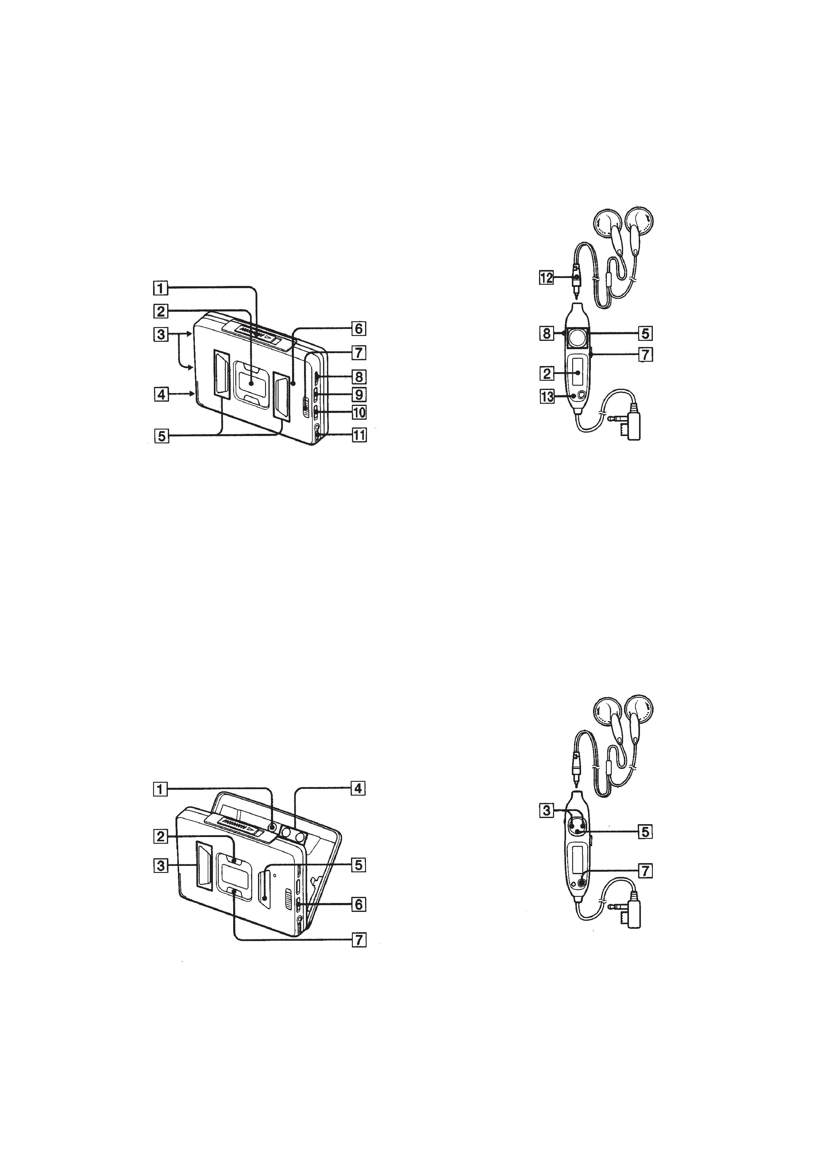
LOCATION AND FUNCTION OF CONTROLS
Tape player section and general
· Main Unit
Radio section
· Main Unit
· Headphones with Remote Control
Left Right
· Headphones with Remote Control
Left Right
1 OPEN button
2 Information display
3 Contact for dry battery case
4 Rechargeable battery case
5 Tape operation buttons
6 BATT indicator
7 HOLD switch
8 Main unit : VOLUME knob
Remote control : VOL knob
9 Åa (Tape direction),
BL SKIP (Blank skip) switch
!º a(DOLBY) NR switch
!¡ 2 REMOTE jack
!TM Micro plug
!£ SOUND/AVLS button
1 ENTER button
2 ASP (Auto Station Preset) button
3 PRESET +, button
4 TUNE +, button
5 p, RADIO OFF button
6 FM ST/MONO switch
7 BAND, RADIO ON button