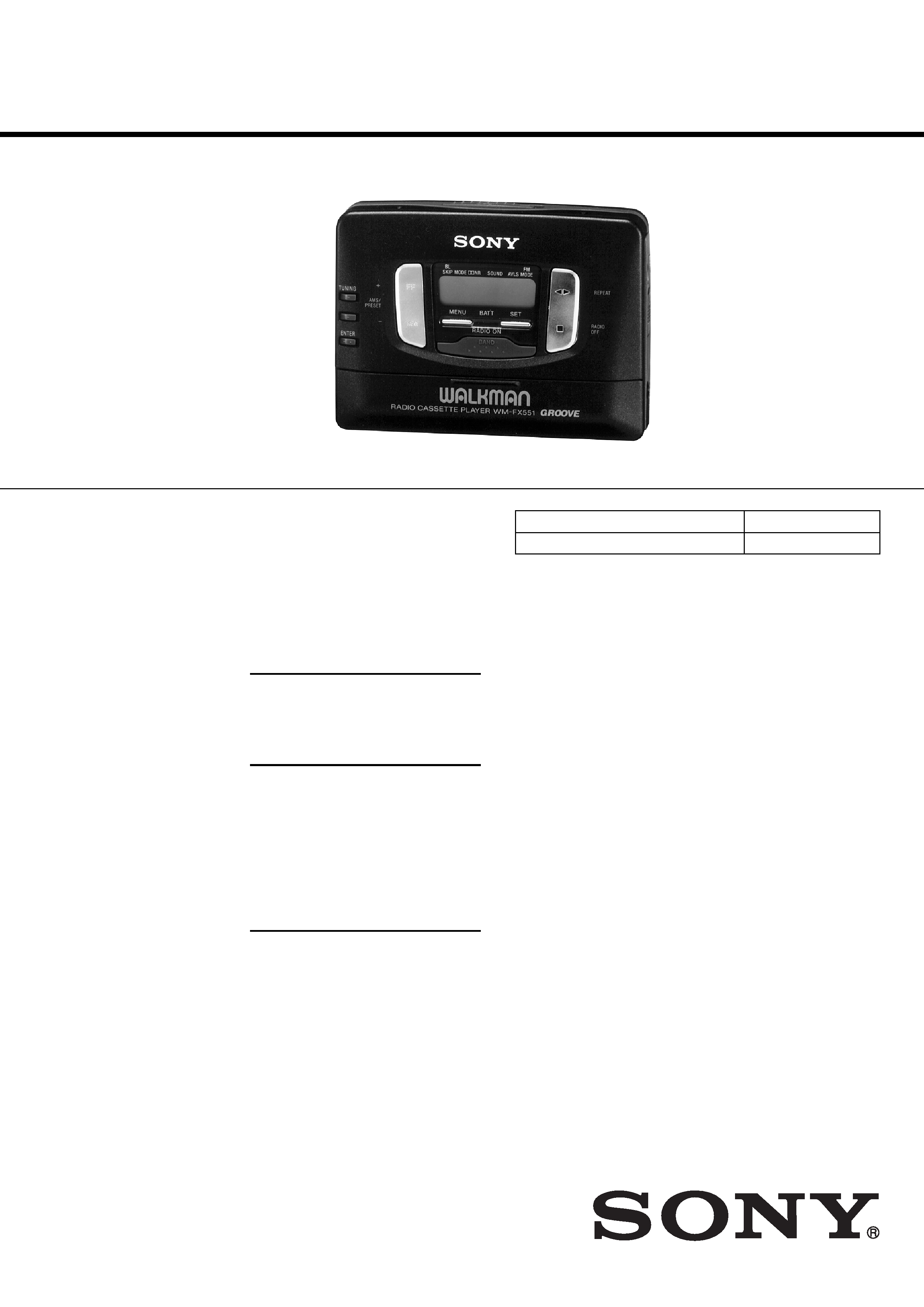
WM-FX551/FX553
AEP Model
E Model
WM-FX551/FX553
US Model
Canadian Model
Tourist Model
WM-FX553
SERVICE MANUAL
RADIO CASSETTE PLAYER
Sony Corporation
Personal Audio Company
Published by Sony Engineering Corporation
9-923-156-12
2002A1600-1
© 2002.1
WPhoto : WM-FX551
Ver 1.1 2002. 01
SPECIFICATIONS
Radio section
Frequency range
FM : 87.5 - 108 MHz
AM : 531 - 1,602 kHz
Tape section
Frequency response
(Dolby NR off)
Playback : 20 -18,000 Hz
Output
Headphones (2 REMOTE jack)
Load impedance 8 - 300 ohms
Power output
5 mW + 5 mW (16 ohms)
General
Power requirements
1.5 V
Dimensions (w/h/d)
Apporx. 109
× 79.2 × 25.9 mm, incl.
projecting parts and controls
Mass
Approx. 150 g
FX553 : Approx. 175 g incl.
headphones with remote control
and cassette
FX551 : Approx. 160 g incl.
headphones and cassette
Supplied accessories
Stereo headphones with remote
control (1) (FX553)
Stereo headphones (1) (FX551)
Clip (1) (FX553)
Carring pouch (1)
Design and specifications are subject to
charge without notice.
Manufactured under license from Dolby Laboratories
Licensing Corporation.
"DOLBY" and the double-D symbol a are trademarks
of Dolby Laboratories Licensing Corporation.
Model Name Using Similar Mechanism
NEW
Tape Transport Mechanism Type
MT-WMEX550-125

-- 2 --
TABLE OF CONTENTS
Flexible Circuit Board Repairing
·
Keep the temperature of the soldering iron aroud 270° C during
repairing.
·
Do not touch the soldering iron on the same conductor of the
circuit board (within 3 times).
·
Be careful not to apply force on the conductor when soldering
or unsoldering.
Notes on chip component replacement
·
Never reuse a disconnected chip component.
·
Notice that the minus side of a tantalum capacitor may be
damaged by heat.
Specification ················································································· 1
1. GENERAL ·········································································· 3
2. SERVICE NOTE ······························································· 3
3. DISASSEMBLY
3-1. Case Assy Removal ······················································· 4
3-2. Tuner Board Removal ···················································· 4
3-3. Audio Board Removal ··················································· 5
3-4. Cassette Lid Assy Removal ··········································· 5
3-5. Mechanism Deck Removal ············································ 6
4. MECHANICAL ADJUSTMENT ·································· 7
5. ELECTRICAL ADJUSTMENT ···································· 7
6. EXPLANATION OF IC TERMINALS ························· 9
7. DIAGRAMS
7-1. Printed Wiring Boards (Tuner Section) ······················· 11
7-2. Schematic Diagram (Tuner Section) ··························· 15
7-3. Schematic Diagram (Audio Section) ··························· 18
7-4. Printed Wiring Board (Audio Section) ························ 21
8. EXPLODED VIEWS
8-1. Cabinet Section ··························································· 27
8-2. Audio, Tuner Board Section ········································ 28
8-3. Mechanism Section (MT-WMEX550-125) ················· 29
9. ELECTRICAL PARTS LIST ······································· 30
The components identified by mark ! or
dotted line with mark ! are critical for safety.
Replace only with part number specified.
Les composants identifiés par une marque
!
sont critiques pour la sécurité.
Ne les remplacer que par une pièce portant
le numéro spécifié.
-- 3 --
SECTION 1
GENERAL
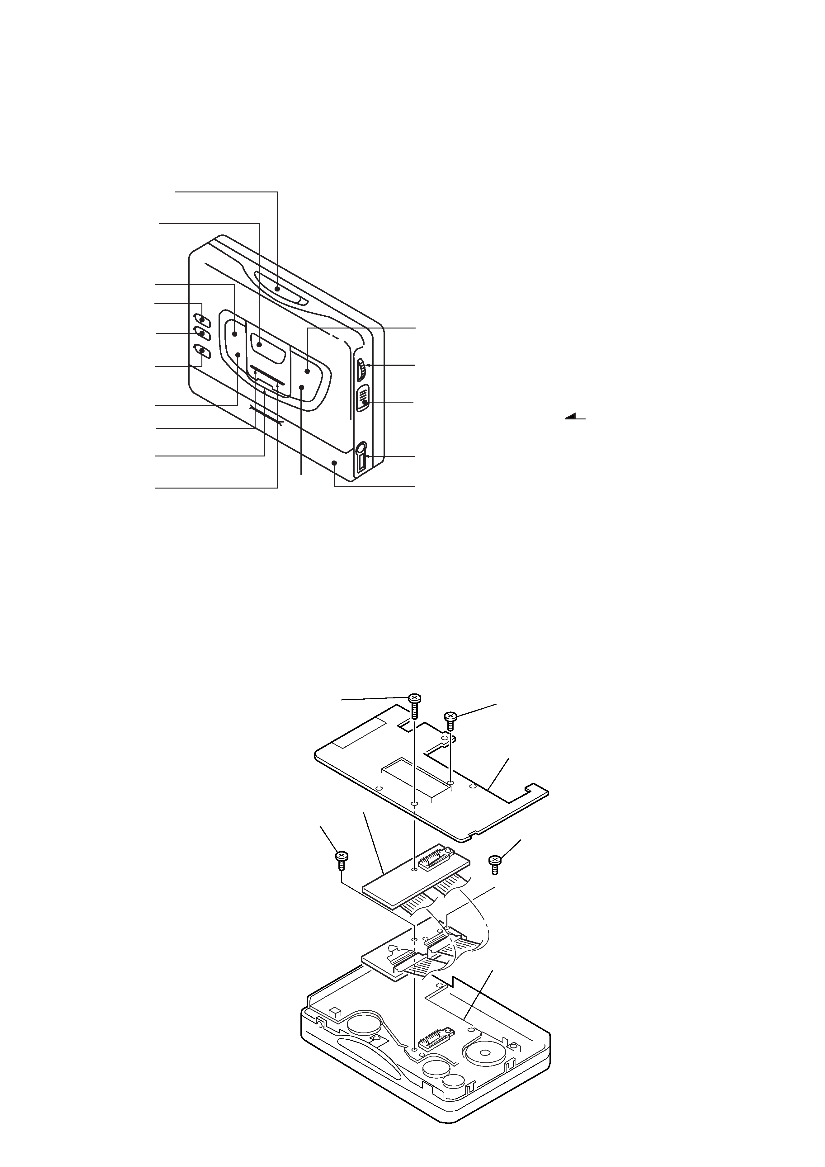
· LOCATION OF CONTROL
SECTION 2
SERVICE NOTE
· Regarding the method of adjustment and voltage check, perform sections 3-1 and 3-2 of the DISASSEMBLY, and attach the JIG to the
AUDIO board as shown below.
1
!¢
2
4
5
6
3
9
!
0
8
!£
!/
!/
Battery case
!"
!`
7
1
OPEN knob
4
TUNING + button
6
ENTER button
7
/REPEAT button
8 p
/RADIO OFF button
9
MENU button
0
SET button
!
BAND button
!`
VOLUME knob
!"
HOLD knob
!¢
Display window
!£
2 REMOTE jack
5
TUNING button
2
PRESET + /AMS FF button
3
PRESET /AMS REW button
Screw
(M1.4
× 5.0)
Screw (M1.4
× 5.0)
TUNER board
Screw (M1.7
× 4.0)
Screw
(M1.4
× 5.0)
JIG
AUDIO board
-- 4 --
SECTION 3
DISASSEMBLY
Note : Follow the disassembly procedure in the numerical order given.
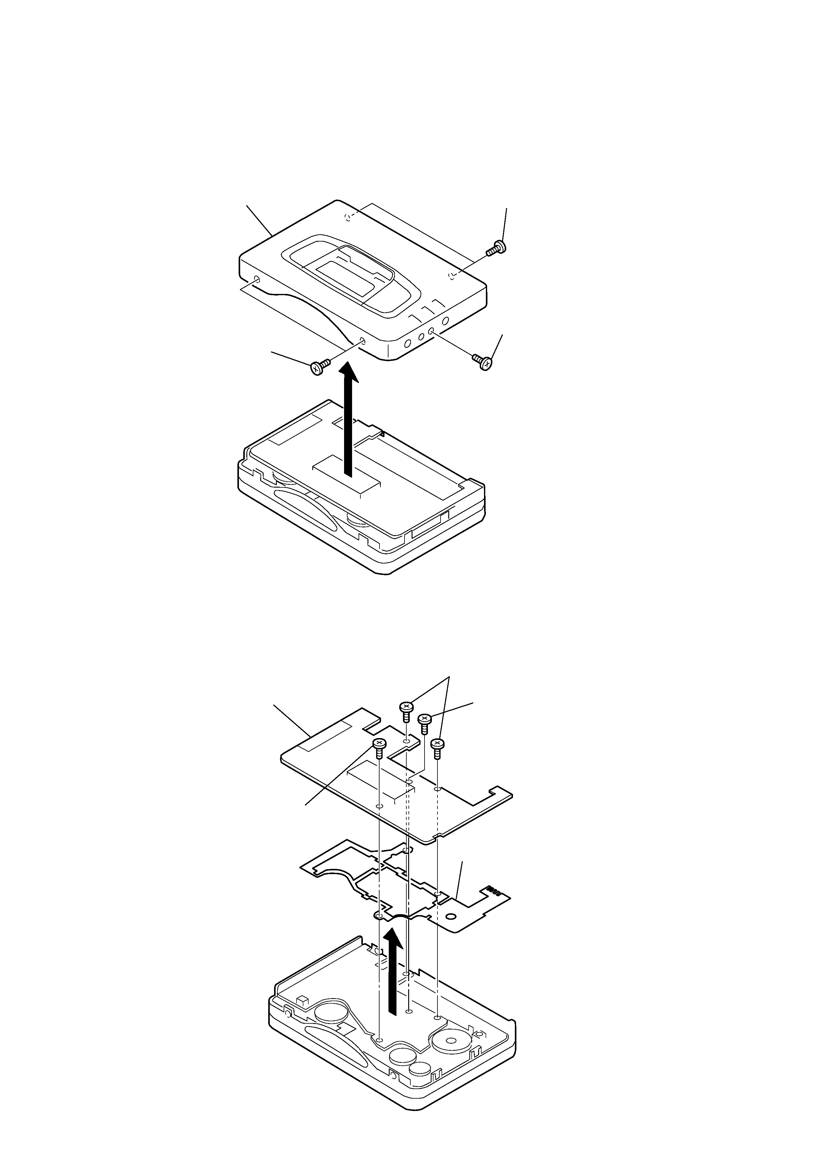
3-1.
CASE ASSY REMOVAL
3-2.
TUNER BOARD REMOVAL
5
Case assy
3
Screw
(M1.4
× 2.2)
1
Screw
(M1.4
× 2.2)
2
Screw
(M1.4
× 2.2)
4
1
Scew (M1.7
× 6)
4
TUNER board
3
Scew
(M1.4
× 4.5)
6
GUIDE (TU )
5
2
Scew (M1.7
× 3)
-- 5 --
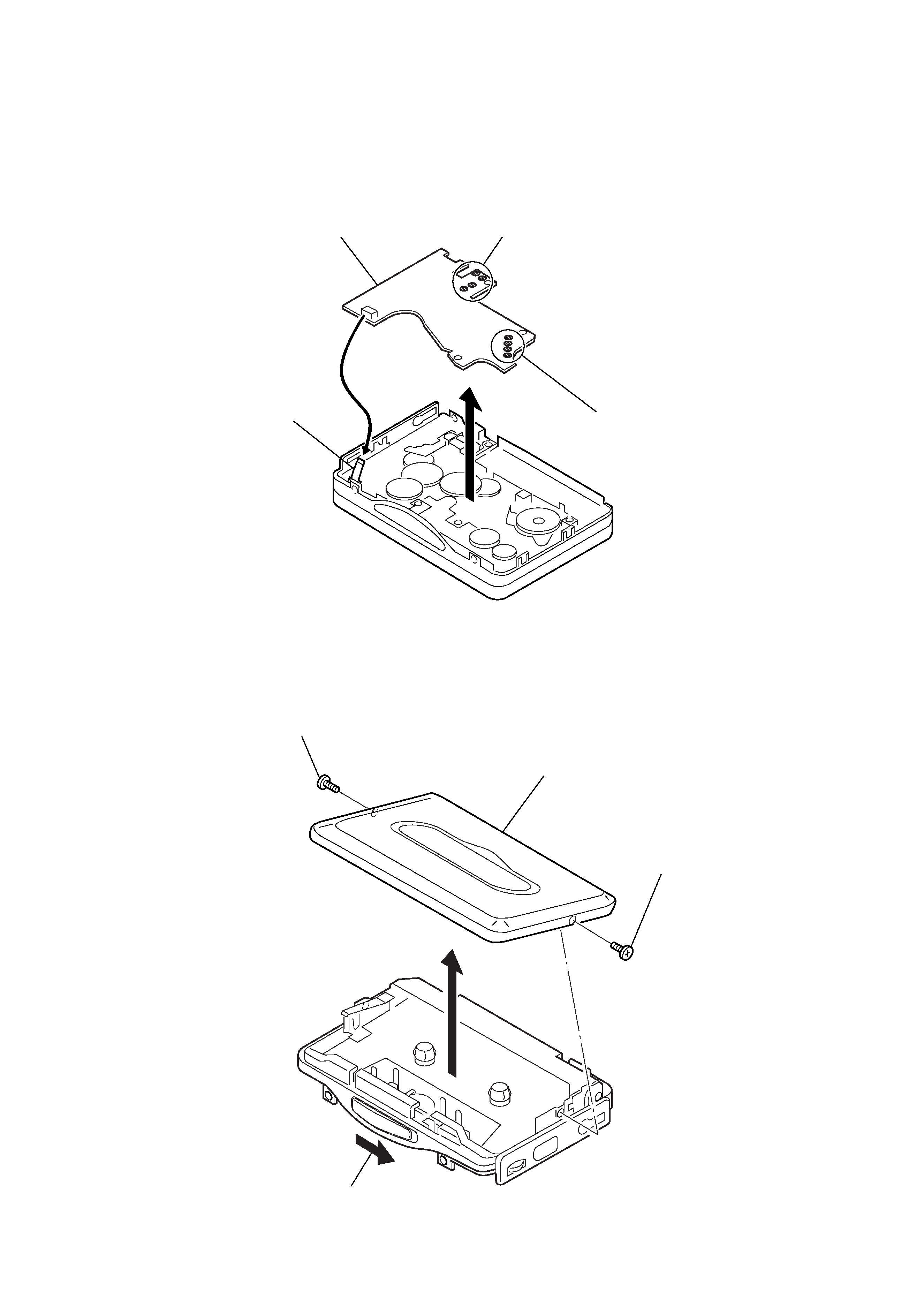
3-3.
AUDIO BOARD REMOVAL
3-4.
CASSETTE LID ASSY REMOVAL
5
AUDIO board
1
Remove solder
2
Remove solder
3
Flexible board
4
2
Screw (M1.4
× 2)
5
Cassette lid assy
3
Screw (M1.4
× 2)
1
OPEN button
4