Ver 1.0 2001.04
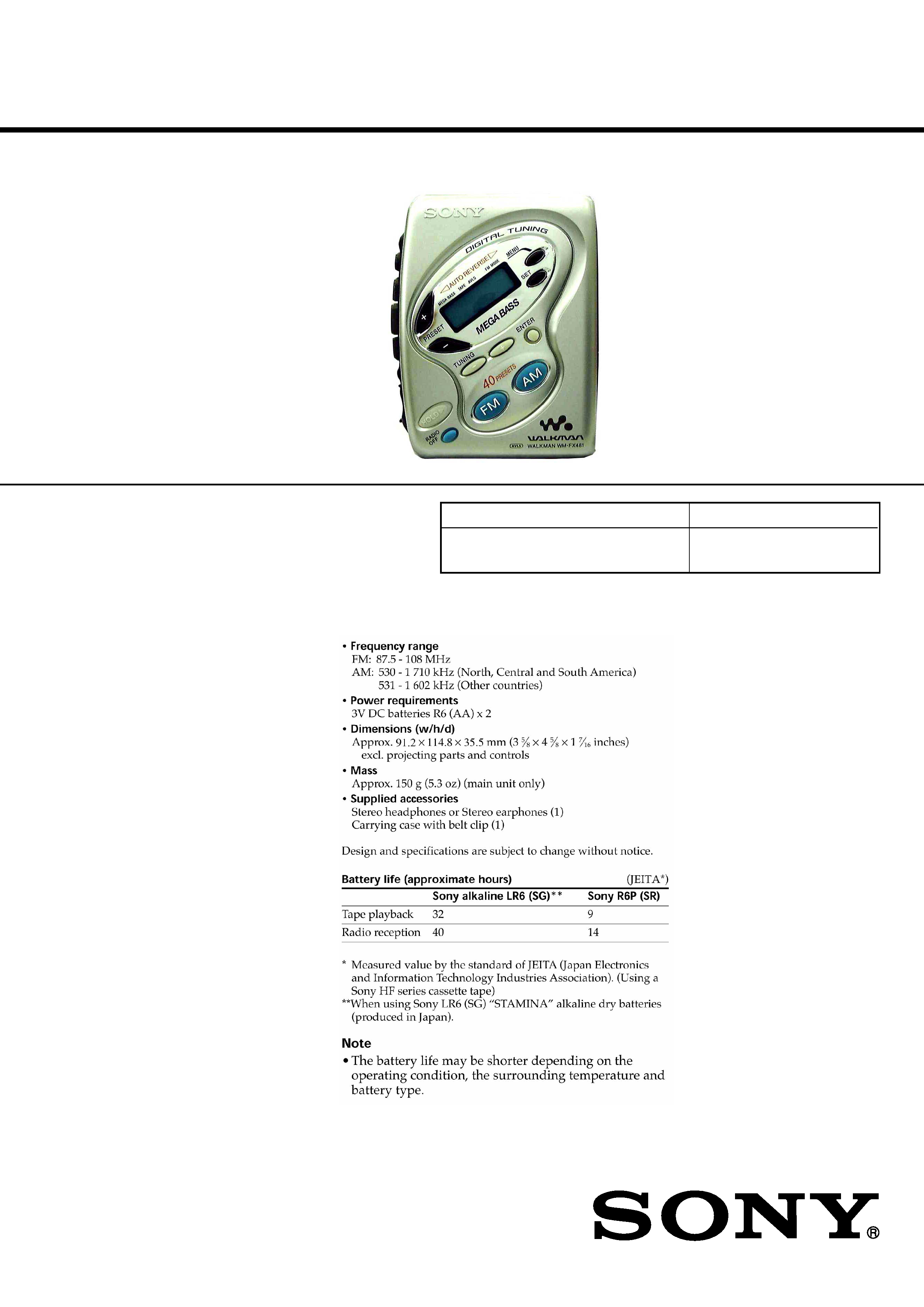
WM-FX481
SERVICE MANUAL
RADIO CASSETTE PLAYER
SPECIFICATIONS
E Model
Chinese Model
Model Name Using Similar Mechanism
NEW
MD Mechanism Type
MF-WMFX481-114 (5E, 6E, 9E)
MF-WMFX467-114 (CH)
9-873-125-11
2001D0200-1
© 2001.4
Sony Corporation
Personal Audio Company
Shinagawa Tec Service Production Group
· Abbreviation
CH
: Chinese
9E
: No Indication of country of origin
5E, 6E : Indication of country of origin
2
WM-FX481
Specifications ........................................................................... 1
1. GENERAL ...................................................................... 2
2. DISASSEMBLY
2-1. Cabinet (Front), Cabinet (Center) Sub ASSY ............ 3
2-2. Main Board ................................................................. 3
2-3. Mechanism Deck ........................................................ 4
2-4. Belt, Capstan/reel Motor (M601),
Magnetic Head (Playback) (HP601) ........................... 4
2-5. Cassette Holder ........................................................... 5
3. ADJUSTMENTS
3-1. Mechanical Adjustments ............................................. 6
3-2. Electrical Adjustments ................................................ 6
4. DIAGRAMS
4-1. Explanation of IC Terminals ....................................... 9
4-2. Block Diagram .......................................................... 10
4-3. Schematic Diagram .................................................... 11
4-4. Printed Wiring Boards Main Section (Side A) ... 12
4-5. Printed Wiring Boards Main Section (Side B) ... 13
5. EXPLODED VIEWS
5-1. Cabinet Section ......................................................... 15
5-2. Mechanism Deck Section
(MF-WMFX467-114:CH)
(MF-WMFX281-114:5E, 6E, 9E) ..... 16
6. ELECTRICAL PARTS LIST ................................... 17
Flexible Circuit Board Repairing
· Keep the temperature of the soldering iron around 270
°C during
repairing.
· Do not touch the soldering iron on the same conductor of the
circuit board (within 3 times).
· Be careful not to apply force on the conductor when soldering or
unsoldering.
Notes on chip component replacement
· Never reuse a disconnected chip component.
· Notice that the minus side of a tantalum capacitor may be dam-
aged by heat.
TABLE OF CONTENTS
SECTION 1
GENERAL
3
WM-FX481
SECTION 2
DISASSEMBLY
Note : Follow the disassembly procedure in the numerical order given.
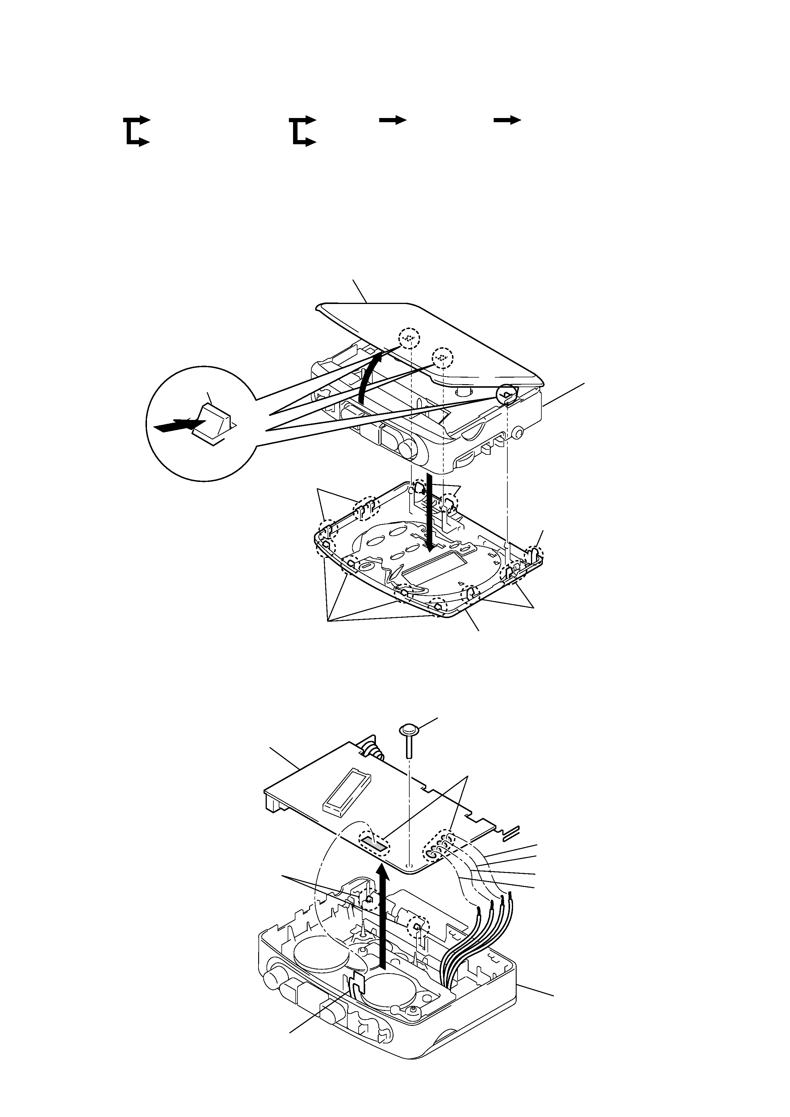
2-1. CABINET (FRONT), CABINET (CENTER) SUB ASSY
2-2. MAIN BOARD
z
The equipment can be removed using the following procedure.
Main board
Cabinet (center) sub ASSY
Cassette holder
Mechanism deck
Belt, Capstan/reel motor (M601)
Magnetic head (playback) (HP601)
Set
Cabinet (front)
Note : Use the precision driver with coverd a point
by cloth to release the claw.
Be careful not to damage claws.
Cabinet (Front)
Cabinet (center) sub ASSY
Cassette holder
4
Claw
4
Claw
2
5
1
Claws
1
Claws
3
Claws
1
Claws
Main board
1
Screw
Orange
Black
White
Red
Cabinet (center) sub ASSY
Head flexible board
2
Remove solder
3
Claws
4
4
WM-FX481
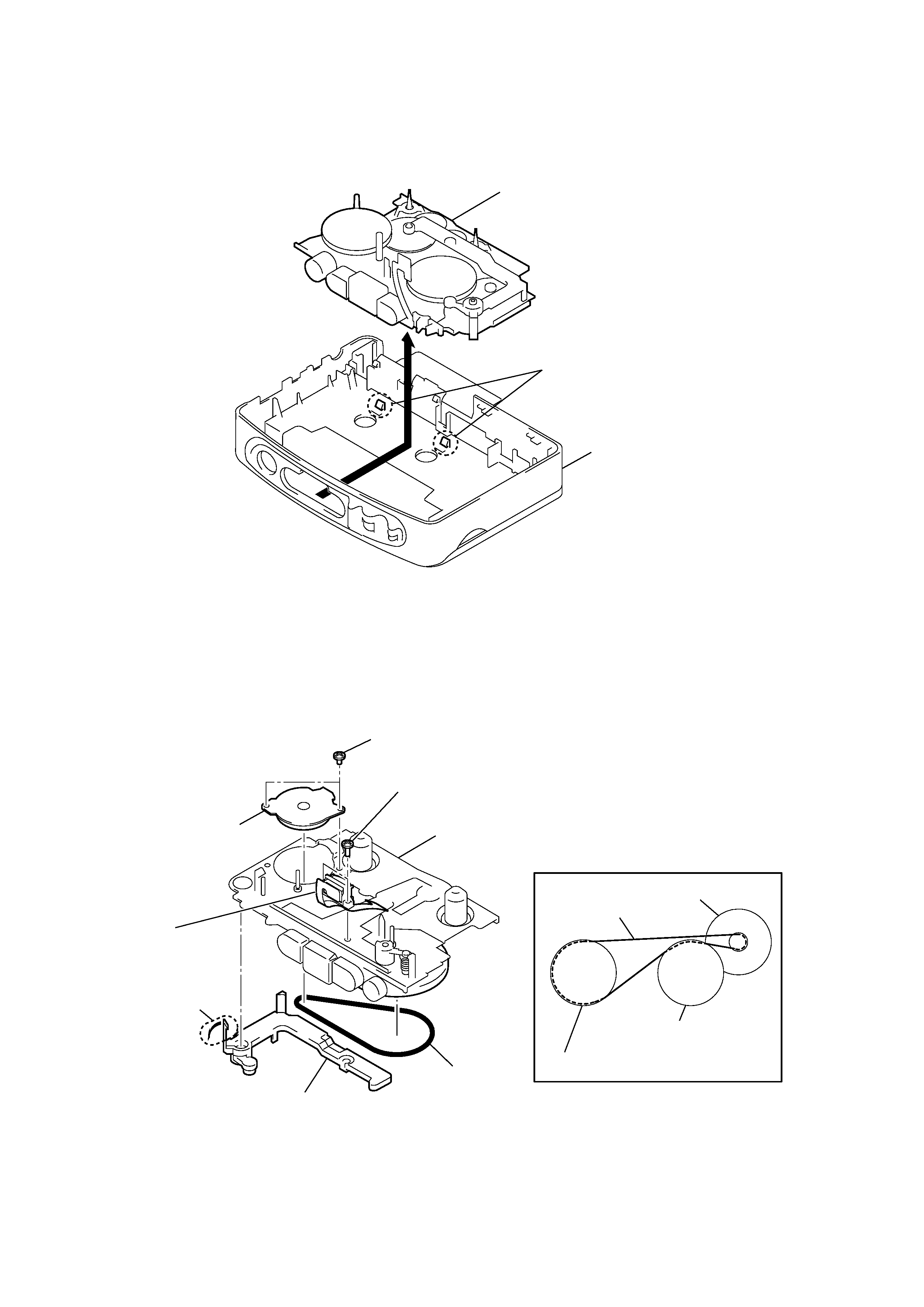
2-3. MECHANISM DECK
2-4. BELT, CAPSTAN/REEL MOTOR (M601), MAGNETIC HEAD (PLAYBACK) (HP601)
Mechanism deck
Cabinet (center) sub ASSY
1
Claws
2
wheel ASSY (P), capstan
wheel ASSY (P), capstan
Belt
· How to apply the belt
Capstan/reel motor
(M601)
2 Belt
Stopper
1 Claw
6 magnetic head
(PLAYBACK)
(HP601)
4
Capstan/reel motor
(M601)
3
Screws (M1.4)
5
Screws (M1.4)
Mechanism deck
5
WM-FX481
1
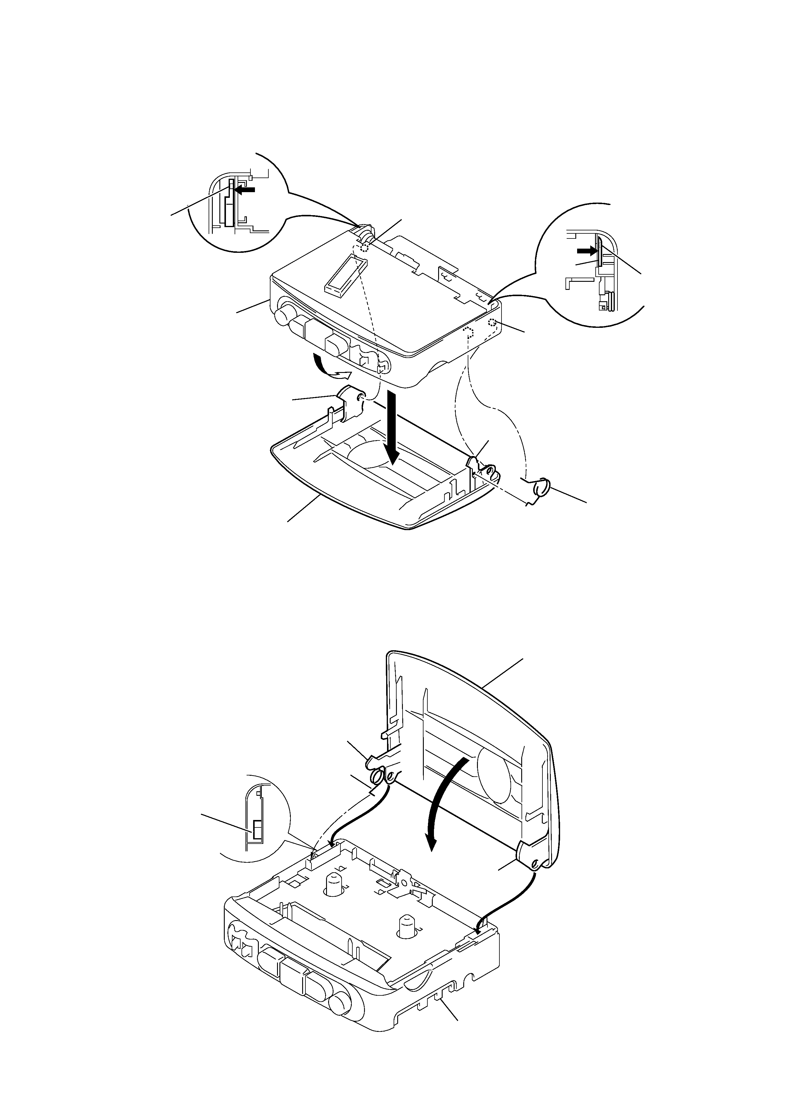
Insert the spring (torsion) to the L shape slot as shown in the figure.
2,3 Insert the hinge of the "Cassette holder ".
4
Close the "Cassette holder" then press it.
2-5. CASSETTE HOLDER
z
CAUTIONS DURING ASSEMBLY
Cassette holder
4
Spring (torsion)
1
5
Hinge
Cabinet (center)
sub ASSY
Hinge
Projection
Projection
Hinge
Hinge
Projection
Projection
3
Move the hinge away
from projection
2
Move the hinge away
from projection
L shape slot
Spring (torsion)
Hinge
Hinge
Cassette holder
Cabinet (center) sub ASSY
1
2
4
3